OrCAD X Free Viewer: A PCB Schematic Viewer and More
Key Takeaways
-
Schematic viewer software allows reviewers to interact with design files without editing privileges – great for established designs or ongoing work.
-
Reviewers can utilize the OrCAD X Free Viewer or view design files within cloud-enabled Workspaces for OrCAD X Capture.
-
The OrCAD X Free Viewer is an all-in-one view tool for all PCB design files, not just schematics.

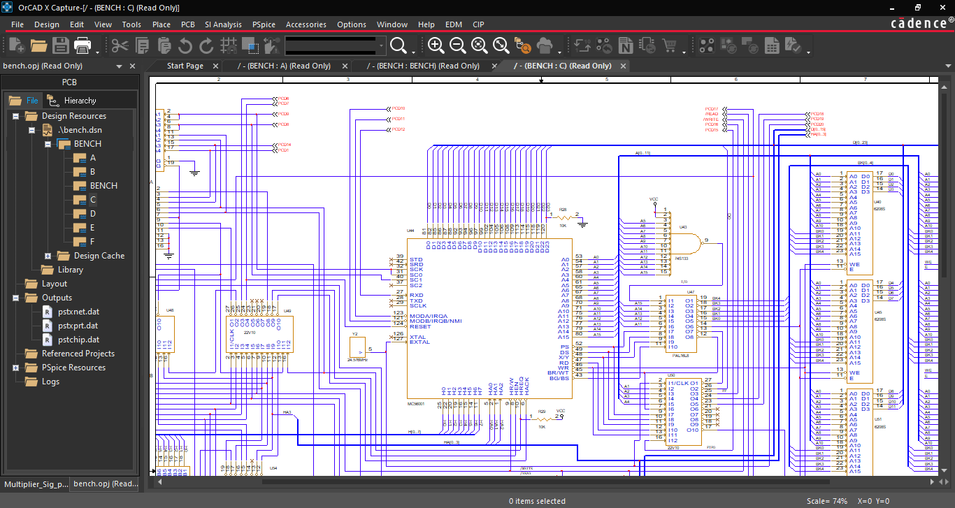
A PCB schematic viewer lets reviewers access a read-only version of schematic files. OrCAD X Free Viewer offers much more.
Schematics are the seeds of board design: while they don’t dive into the physical specifics of how connections link components, they symbolically represent the fundamental networking at the board level. As such, they are among the most critical design files, as errors here can result in manufacturing defects or runtime errors that can result in a scrapped production lot.
Since the schematic is the earliest point at which a design tends to crystallize, many departments involved in manufacturing or manufacturing-adjacent processes will want to access this document at the earliest opportunity for a seamless transition into production. A PCB schematic viewer grants these users access without endangering the design integrity, as the program is read-only and restricts editing to the engineers and designers. The OrCAD X Free Viewer supports schematic viewing and additional support for board file and library viewing for a comprehensive design document viewer.
Where to Start With OrCAD X
|
OrCAD X Free Viewer |
OrCAD X Free Trial |
OrCAD X |
|
|
Can |
|
|
|
|
Cannot |
|
|
|
Two PCB Schematic Viewer Methods With OrCAD X
The schematic communicates circuit connectivity at the highest level (i.e., purely logical) and provides general organization to the layout before accounting for the specific physical requirements of the topology. As such, design review flows through the schematic after initial simulation by the engineering team, and any changes require communication per engineering change orders (ECOs) to maintain design intent. On the path to manufacturing, many departments will need to check various aspects of the schematic to prevent issues from unoptimized design performance to incorrect/unavailable component requests during procurement.
The importance of the schematic means its integrity is paramount: small changes made knowingly or otherwise can dramatically affect the boards’ performance and profitability. Especially for users less familiar with the OrCAD X platform, restricting team members who are neither layout designers nor engineers can save time and money spent correcting these issues once discovered (ideally, pre-manufacturing). Fortunately, OrCAD X offers multiple methods for design teams to selectively restrict/permit access to these vital design files while still maintaining a welcoming UI that keeps design reviews progressing promptly:
-
The OrCAD X Free Viewer supports schematic viewing and other file types like board files, drawings, and module definitions. The free viewer features the same streamlined approach to the UI as the paid software version, and users can quickly filter between schematic pages and check properties to find the information they’re looking for faster.
-
The Workspace feature in OrCAD X Capture allows an administrator to define team collaboration by setting view/edit privileges for libraries and project files, including schematics. Checking in/out by editing and publishing keeps version history linear to prevent data overwrites.
OrCAD X Free Viewer Capabilities
By nature of operating on the same platform as the full-capabilities OrCAD X Capture, the OrCAD X Free Viewer has much more limited functionality; designers interested in growing the feature set should check out the OrCAD X Free Trial to get a better handle on the power and ease of the new OrCAD X platform. However, some basic functionality – e.g., targeted printing sans templates for internal communications – is still present that can improve design reviews:
-
Footprint verification - Since the assembly's reliability depends on the footprint's accuracy to manufacturer specifications, design teams must incorporate a verification procedure to prevent PCBA production defects.
-
Cross-section report: Reviewers can see a breakdown of the stackup by material and thickness, including various electrical parameters like the dielectric constant, conductivity, and loss tangent that can accurately gauge real-world performance within an electromagnetic field solver.

A Cross-Section Report gives reviewers basic information about the stackup.
-
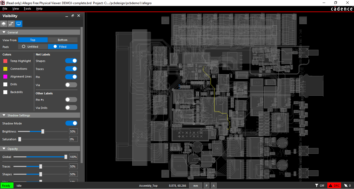
Net coloring - Like cross-probing, reviewers can color nets to quickly identify critical signals like clocks and how the surrounding layout can influence or become influenced by them.

Viewer options, like brightness, saturation, and layer visibility, allow reviewers to highlight critical nets against the background design.
-
Capture Canvas - Reviewers can take a screenshot of their active canvas for internal communications, comments, and critique without operating various third-party screenshot tools.
-
Package review - Reviewers can inspect complex multi-die packages, including design features like wire bonds, silicon bridges, interposers, etc.
View More and Do More With Cadence Solutions
A PCB schematic viewer grants team members with diverse skills and backgrounds the ability to confidently review design documents without worrying about harming the file integrity or check-in/check-out privileges. However, the OrCAD X Free Viewer isn’t just a schematic viewer; it can also review board and library files for a comprehensive tool suited for all stages of product design. Built with the same user-friendly interface as the new OrCAD X platform, team members of all levels of ECAD experience will benefit from faster turnaround times. Cadence PCB Design and Analysis Software pushes the boundaries of innovation for all things electronic.
Leading electronics providers rely on Cadence products to optimize power, space, and energy needs for a wide variety of market applications. To learn more about our innovative solutions, talk to our team of experts or subscribe to our YouTube channel.