A Guide to PCB Connectors: Selection, Design, and DFM Tips
When it comes to interconnects for our printed circuit boards, I found one vendor with 25,217 options. A specialty vendor only offered about 9,000 different connector SKUs. Luckily, you can usually winnow down to the number and pitch of the pins, along with other parameters, to find a connector that does what you want.
To be honest, the parametric part numbers were the thing that bothered me about capturing connector footprints. There would be a few letters to designate the family, followed by a series of numbers that flesh out the characteristics of each connector. Imagine the old days, thumbing through a catalog to find the style of connector, then parsing through other pages to decode the numerous details regarding all of the options. There was one drawing, and it covered about 300 different connector configurations for the whole family of connectors.
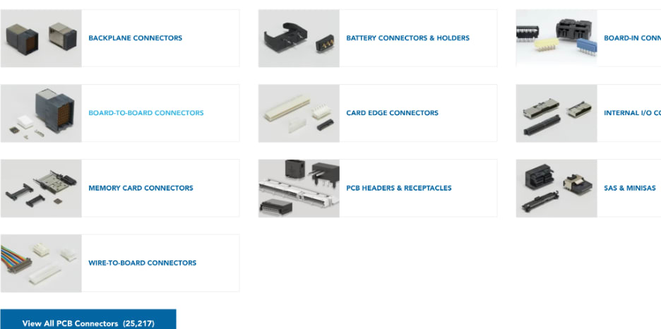
Figure 1. Narrowing down our search to just PCB connectors brings back 25,217 results from one vendor. These 10 options fan out to almost limitless configurations. Image Credit: TE Connectivity
The good news is that there will likely be a table that provides the overall size values of the connector body based on the number of pins by rows and columns. The length of any through-hole pins will be another option that corresponds to the PCB thickness. Larger connectors will feature alignment pins or holes for mounting hardware. Retention clips are common with higher pin-count connectors.
The type of plating is usually immaterial to the footprint geometry but will usually be incorporated somewhere in the vendor part number. Alignment pins are one of those areas where a connector vendor will push the limits of what can be constructed on the printed circuit board. Positional and size tolerances can be too tight.
Other miscellaneous issues could also crop up. The gap between a non-plated hole and a SMD pin can be too small for the PCB fabricator. Beware of a board thickness callout that is non-manufacturable. Component Engineers earn their money when they have to qualify a connector scheme. The Board Designer is a backstop for the DFM requirements. The board will be as good as you make it. How it interfaces with the world depends on your judgement.
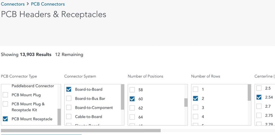
Figure 2. Filtering the search to find Board-to-Board receptacles with 60 positions using two rows on 0.1” pitch, plated holes with vertical launch narrows the field from 13,903 possibilities down to twelve. There are 24 further fields to specify just about any requirement missed by the first few attributes. If you can’t find a connector among these, there are outfits that will create connectors to order. Image Credit: TE Connectivity
Just like any component vendor, the connector industry wants to give their product the best odds of success. That innate desire to not be a spectacular failure is a strong incentive to over-constrain the design. That’s how you see tolerances that get flagged during the Design For Manufacturing cycle at the fab shop. This is the wrong time to find out that you need a compromise somewhere. A call ahead of time can save the end game.
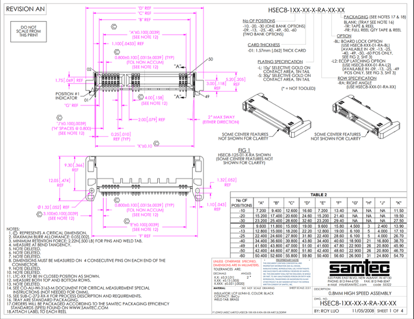
Figure 3. The title page of a typical connector drawing includes a decoder for the part number and the standard views. The other three pages have cross-section cutaway views and various details but no actual PCB footprint recommendations. We do have a pin-one indicator so that’s a good start. Image Credit: Samtec
Now for the fine print: The upper left corner of the title block is set aside to note the tolerance allowance based on the number of digits to the right of the decimal point for each dimension. The dimension with the tightest tolerance would be any dimension with three digits where the maximum deviation from the print is +/- .050mm (+/- 2 mils). Most of the dimensions use two digits past the dot where you get a more reasonable tolerance of +/- 0.13 (5 mils).
These connector dimensions sometimes creep over to PCB outline dimensions and, of course, board thickness. Checking the component footprint should include considering the DFx guidelines that your likely vendor chain would require in reference to the dimensions and tolerance stack-ups of the single board.
Given that connectors are often on the edge, the spacing requirements for engagement and disengagement come into play. Compared to some connectors, our fingers look like they are on the hand of The Incredible Hulk. For some of those ham-fisted Army Sergeants, that may be true, so we always have to be aware of the airspace around a connector.
Sometimes, Everything Has To Be Connectorized
I’m thinking back to the mistake I made on a program where these little modules were connected together inside a housing using SMA connectors and semi-rigid coax. It was the RF amplifier for a portable radar system. It was one thing to create a drawing of all of the sub-units put together. It was another thing to try to explain how we would be able to get a wrench into each location to tighten the SMA cables.
A few of the modules had to be connected together with the semi-rigid cables before we could bolt them down inside the modular housing for the amplifier. Luckily semi-rigid cable can be bent a little without too much trouble. My manager and I had to sit down to work out a convoluted assembly process. From the time of that debacle onward, I paid keen attention to the whole life cycle when planning out the connector scheme.
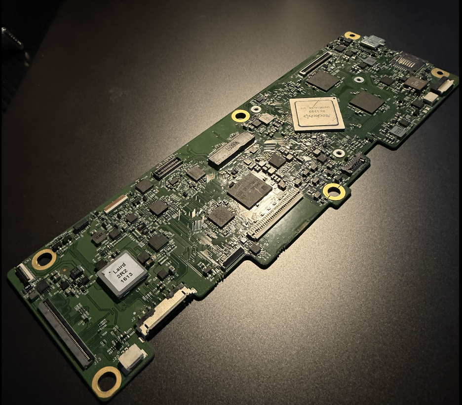
Figure 4. I count 16 connectors on the perimeter of this Main Logic Board for a Chromebook. It's about a 50/50 mix of flex circuits and wired connectors. The USB type C connector has through-hole pins. That and the SD card holder are the only user interfaces. Image Credit: Author
Sometimes, it’s better to make a wire too long and have a service loop included with the wire break-outs. The point here is to escape the 2-dimensional mindset of our PCB design philosophy and consider the process from fabrication to SMD to second op and final test right from the beginning. There has to be space provided for the hardware to meld into a producible product and come apart again if necessary.
When space is limited, the flex circuits thrive. They are an ecosystem of their own. Their specialty is the ability to conform to contours using a minimum of material thickness. They are used extensively in phones, extended reality headsets, and laptops, to name a few. As an aside, the only time I’ve encountered a rigid flex PCBA is in aerospace. That is an approach to take when a loose connector could turn a satellite in orbit into space junk. We still use connectors for automotive applications, but they come with derated wiring and over-built clamps to keep them safe and secure.
Taking Interconnections To The Next Level
Data centers are the place where the leading edge of connector design plays out. Fiber optics are a key pipeline around the data center and may be prying its way into the IT closet of your typical enterprise. Those fiber optic connectors used to be limited to the edge of the board using transceivers in little metal cages. Connecting the fiber is one of those high-precision affairs where missing the lens by just a mite causes signal integrity issues.
There is a lot of copper in between the chip and the board edge, so mid-board optical connections have become more common. Board-to-Board connections are supplemented with Board to Chip and Chip-to-Chip topology, along with the intersystem connections of the past. This is when some of those other attributes come into play. We would select for high data rates and better flammability ratings and, of course, lots of pins. I will come back to this advanced connector topic after DesignCON 2026 is in the books. That convention is about two things: connectors and everything else. Hope to see you there.