Magnetics First: How Transformer Choices Make or Break Your Design
The transformer is the heart of every flyback. And like most hearts, it's easy to take for granted until something goes wrong.
I've seen engineers spend weeks optimizing control loops, agonizing over capacitor selection, and tuning snubbers, only to discover that the transformer they picked from a catalog doesn't actually work for their application. Wrong turns ratio. Insufficient inductance. Core saturation at high line. Leakage inductance that makes the snubber dissipate more power than the load.
The transformer defines what's possible. Everything else works around its constraints.
For a 5V/2A USB-C adapter running from universal AC input, the transformer choice determines your efficiency, your size, your EMI signature, and whether the design works at all.
What the Transformer Actually Does
In a flyback, the "transformer" isn't really a transformer in the traditional sense. It's a coupled inductor. Energy storage, not just voltage conversion. Here's the operating principle:
Switch ON: Current flows through the primary winding, building a magnetic field in the core. Energy is stored in the magnetic field. The secondary diode is reverse-biased-no energy transfers to the output yet.
Switch OFF: The magnetic field collapses. The voltage across the windings reverses. Now the secondary diode conducts, and the stored energy transfers to the output capacitor and load.
This store-and-release behavior is what makes flyback topologies work for isolated applications. But it also means the core has to store real energy, not just couple it. And that has implications for core size, gap, and saturation limits.
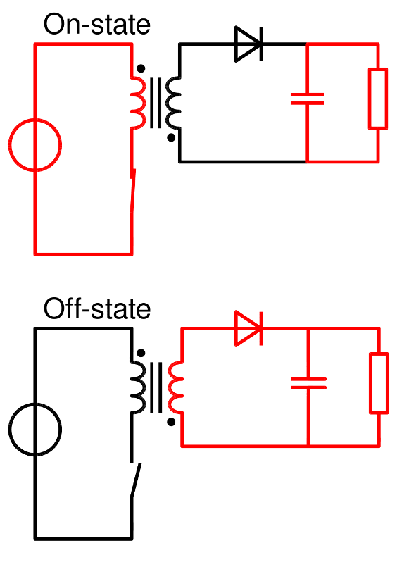
Simple diagram showing flyback operation - two states side by side. Top: switch ON, current in primary, magnetic field building. Bottom: switch OFF, energy transferring to secondary. (Wikipedia)
The Parameters That Matter
When selecting or designing a flyback transformer for a 10W USB-C adapter, these are the critical parameters:
Primary Inductance (Lp)
The primary inductance determines how much energy the transformer stores per switching cycle. For a given power level and switching frequency if the inductance is too low, higher peak currents are required to store the same energy, leading to increased switch stress, higher conduction losses and potentially an inability to deliver full power. Conversely, if the inductance is too high, the transformer takes longer to change, and at low line (85VAC), there may not be enough on-time to store sufficient energy, preventing the design from delivering full power at the low end of the input range.
For a 10W flyback at 65kHz switching, primary inductance is typically in the range of 300-600µH. The exact value depends on your operating mode (DCM vs. CCM boundary) and input voltage range.
Turns Ratio (Np:Ns)
The turns ratio sets the relationship between input and output voltage. For a flyback:
Vout = (Vin × D × Ns) / (Np × (1-D))
Where D is duty cycle.
For universal input (85-265VAC rectified to 120-375VDC) and 5V output, a typical turns ratio is around 12:1 to 15:1. This keeps the duty cycle in a reasonable range across the input voltage span.
Choosing the wrong turns ratio for a transformer can lead to significant issues. If the turns ratio is too high (e.g., 20:1), the duty cycle becomes excessively small at high line, resulting in poor control resolution and reduced efficiency.
On the other hand, if the turns ratio is too low (e.g., 8:1), the duty cycle becomes excessively large at low line, making it impossible to fit the required on-time within each switching cycle. This can cause the output voltage to sag, compromising the performance of the system.
Leakage Inductance (Llk)
This is the portion of the magnetic field that doesn't couple between primary and secondary. It's unavoidable, but it needs to be managed.
When the switch turns off, leakage inductance energy can't transfer to the secondary. it has to go somewhere else. Usually into a snubber, which dissipates it as heat.
For a 10W flyback, leakage inductance might be 3-8µH (roughly 1-3% of primary inductance). Lower is better for efficiency, but transformer construction techniques that minimize leakage (interleaved windings, sandwich construction) add cost.
Saturation Current (Isat)
The core can only store so much magnetic energy before it saturates. At saturation, inductance drops dramatically, current spikes, and Bad Things Happen.
For your design, you need:
Isat > Ipeak × margin
Where Ipeak is your maximum peak primary current (including startup and transient conditions), and margin is typically 20-30%.
If the transformer datasheet says Isat = 2A and your simulation shows peak current of 1.8A during startup, you're cutting it too close. Temperature affects saturation, and you have no margin for transients.
Selecting vs. Designing
For a 10W USB-C adapter, you have two paths:
Off-the-shelf transformer
Many manufacturers offer catalog flyback transformers designed for common applications. For USB adapters, you can find transformers pre-designed for 5V, 10-15W, universal input. These catalog parts offer advantages like fast availability, low non-recurring engineering (NRE) costs, and proven designs. However, they come with limitations, as you're restricted to the manufacturer's specified inductance, turns ratio, and construction, which may not be optimal for your specific needs. Even with a catalog part, it's crucial to simulate it in your circuit to verify its suitability. Check whether the inductance provides the desired operating mode, if the turns ratio works across your input range, and whether the saturation margin is sufficient for your application.
Custom transformer
For higher volumes or specific requirements, work with a magnetics vendor to design a transformer to your specifications. This approach allows for optimization to meet exact requirements, including the ability to specify parameters such as leakage inductance, construction style, and creepage distances. However, it does come with some drawbacks, including NRE costs, longer lead times, and the need for magnetics expertise to ensure the design aligns with your application.
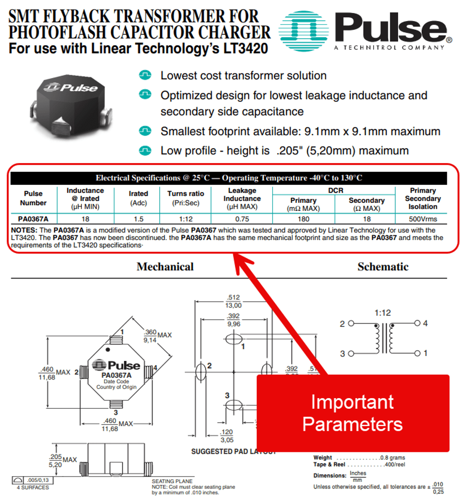
Datasheet excerpt from a catalog flyback transformer, showing key parameters: inductance, turns ratio, Isat, leakage inductance. (Source: Linear Technology)
The Simulation Check
Before committing to a transformer, simulate it in PSpice:
1. Verify operating mode. With your chosen inductance and load, does the design operate in DCM (discontinuous conduction mode) or CCM (continuous)? DCM is simpler to stabilize. CCM can be more efficient but requires different compensation.
2. Check the duty cycle range. At 85VAC input and full load, what's the duty cycle? At 265VAC and light load? Make sure you have margin at both extremes.
3. Measure peak current. During steady state and during startup. Compare to the transformer's saturation current rating.
4. Quantify leakage energy. Measure the voltage spike at switch turn-off. Calculate the power dissipated in the snubber. Is it acceptable for your efficiency target?
5. Verify isolation. The transformer provides galvanic isolation. Make sure the creepage and clearance on the transformer itself meet your safety requirements-this is often specified on the datasheet.
Common Mistakes
Ignoring high-line operation. The design works great at 120VAC. But at 240VAC, the duty cycle is so small that regulation becomes noisy, and efficiency drops because you're switching with tiny on-times.
Underestimating startup current. Steady-state peak current is 1.2A. But during startup, before the soft-start is fully ramped, peak current hits 1.9A-dangerously close to the 2A saturation limit.
Ignoring temperature. Saturation current drops at high temperatures. A transformer rated for 2A at 25°C might saturate at 1.6A at 100°C. Your design needs to work hot, not just at room temperature.
Forgetting about leakage. A cheap transformer with 10% leakage might save $0.20 on the BOM. But the snubber dissipation increases by 0.5W, ruining your efficiency target and requiring a larger enclosure or inconvenient changes for better thermal management.
The Takeaway
Prioritize magnetics first. Before finalizing the control loop, routing the PCB, or selecting the output capacitors, make sure the transformer works. Start by simulating the transformer to evaluate its operating mode, duty cycle range, peak currents, and leakage energy. Verify that the design works at the corners: low line, high line, cold start, and hot operation.
The transformer is the one component you can't fix with a firmware update or a resistor swap. Get it right from the start to avoid costly setbacks and your design not working from the start.