A Flyback That Starts Clean: Modeling Startup & Burden in PSpice
You plug in a USB-C wall adapter. Your phone's screen lights up, and starts charging.
What you don't see: the first 20 milliseconds of chaos inside that little white brick. Input capacitors hit with a surge of inrush current. The transformer magnetizes starting from zero. The control loop is waking up and trying to regulate an output that doesn't exist yet.
Most of the time, this startup sequence goes fine. But when it doesn't, the soft-start is too aggressive, the inrush trips a fuse, the output overshoots and damages downstream electronics, you end up chasing intermittent failures that only appear under specific conditions.
Engineers typically see these on the lab test bench. By then, that's too late.
The fix isn't more bench testing. It's simulating a startup before you build hardware.
What startup looks like when soft-start isn't tuned correctly
In the next sections we'll explore why starting up a power switching converter is so stressful and its moving parts. It's a lot more complicated than you might think.
What Makes Startup So Stressful
Consider what's happening in a 5V/2A isolated flyback during the first few milliseconds after you connect it to wall power:
The input capacitors are empty. When the bridge rectifier starts conducting, voltage switching changes, which causes current to rush into the bulk capacitor with nothing to limit it except the impedance of the AC line and any inrush limiting you've designed in. This current spike can hit 10-20× your steady-state input current.
The transformer starts from zero. The magnetic core has no stored energy. The first several switching cycles behave differently than steady-state because the flux is building from nothing.
The control loop is waking up. The PWM controller has its own startup sequence-reference voltages ramping, oscillators starting, soft-start capacitors charging. During this time, the loop isn't really "in control" yet.
The output is trying to ramp. The 5V rail needs to rise from 0V to 5V in a controlled way. Too fast, and you get overshoot. Too slow, and downstream devices time out waiting for power.
All of this happens simultaneously, and the interactions can be subtle. A soft-start that works fine at room temperature might fail at cold temperatures when capacitor ESR changes. An inrush limiter that's adequate at 120VAC might trip at 240VAC
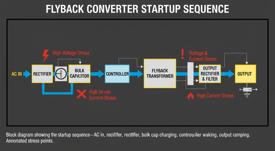
Block diagram showing the startup sequence - AC in, rectifier, bulk cap charging, controller waking, output ramping with typical stress points
What We're Looking For in Simulation
PSpice transient simulation lets you watch startup unfold in detail. The key measurements:
Inrush current peak and duration. For a 10W adapter, your bulk capacitor might be 10-22µF at 400V. The inrush current when charging this capacitor needs to stay within the ripple current rating. For this design, I target less than 3A peak inrush.
Output voltage profile. Does the 5V output ramp smoothly, or does it overshoot? USB-C devices are fairly tolerant, but repeated overshoot to 6V+ will stress downstream components. Ideally, I want voltage overshoot under 5% of that 5V output voltage (i.e. under 5.25V).
Soft-start timing. How long does it take to reach regulation? For a USB-C adapter, 10-30ms is typical. Too fast risks overshoot; too slow and the device you're charging might not recognize the charger.
Switch stress during startup. The peak current through the MOSFET during startup can exceed steady-state values. The simulation shows whether you're within the switch's safe operating area.
Setting Up the Simulation
The simulation needs enough fidelity to capture real startup behavior. Here's what the model includes:
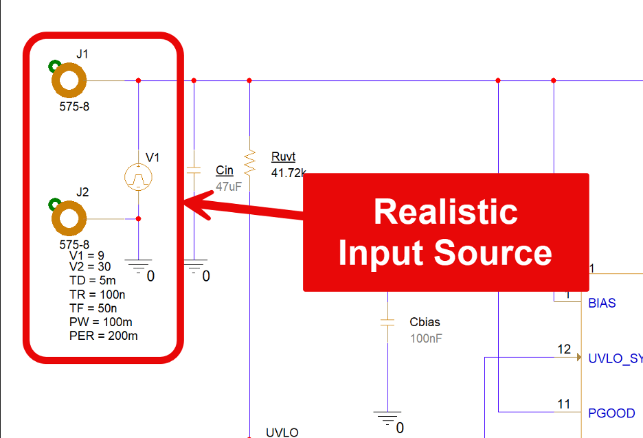
Realistic input source. Not an ideal DC voltage-an AC source with rectification. Startup behavior depends on where in the AC cycle power is applied. I typically run the simulation at the worst-case phase angle (peak of the AC waveform for maximum inrush). If I go DC, I model it using a pulsed voltage that has a delay and realistic rise time and falling time.
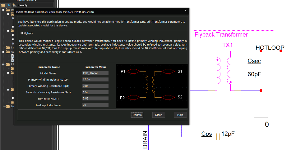
Transformer with parasitics. Key elements are the primary inductance, secondary inductance, leakage inductance, interwinding capacitance, and winding resistance. For a 10W flyback transformer, leakage inductance might be 3-8µH, which affects snubber requirements.
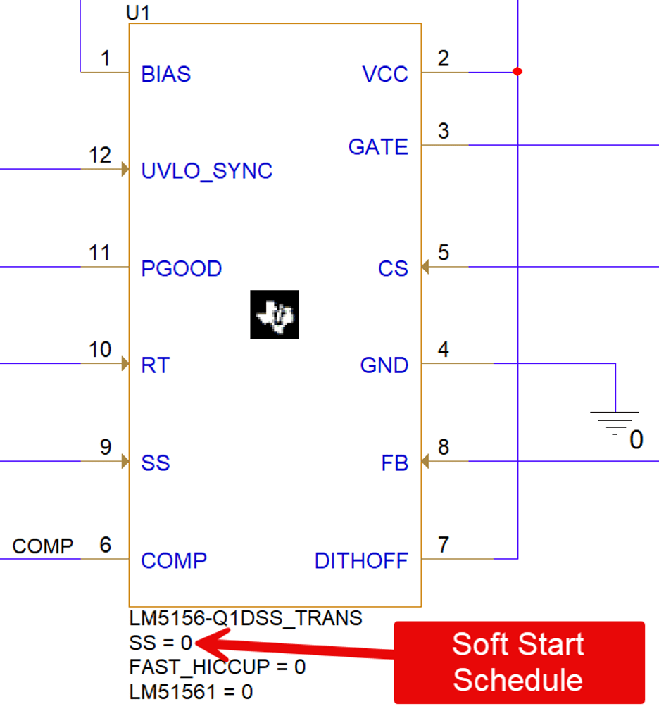
Controller model with soft-start. The PWM controller's soft-start behavior matters. Most controller manufacturers provide PSpice models that include soft-start timing. If not, you can model it with an RC ramp on the feedback node.
Output capacitors with ESR. Ceramic capacitors have low ESR; electrolytics have higher ESR. The ESR affects output ripple and transient response during startup.
Representative load. For USB-C, I model a constant-current load that steps on after the output reaches a threshold-simulating a device that waits for power-good before drawing current.
PSpice schematic screenshot showing the simulation of a Flyback Converter
Reading the Startup Waveforms
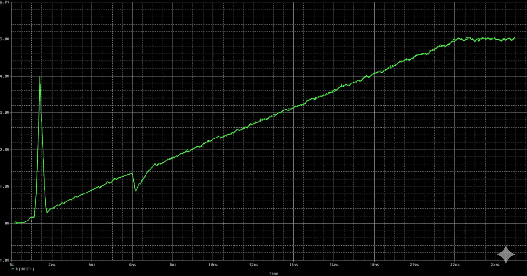
Here's what the simulation reveals for this 5V/2A design:
|
Time Interval (ms) |
Event |
Details |
|
t = 0-2ms |
Bulk capacitor charging |
Input current spikes to 2.4A as the 22µF bulk capacitor charges through the bridge rectifier. This is within the capacitor's 3A ripple rating. The NTC inrush limiter (if present) reduces this further. |
|
t = 2-5ms |
Controller startup |
The controller's VCC capacitor charges from the auxiliary winding (or startup resistor). The oscillator starts, but the soft-start capacitor holds the duty cycle low. |
|
t = 5-18ms |
Soft-start ramp |
The output voltage rises linearly from 0V to 5V as the soft-start capacitor charges. Switch current increases gradually, never exceeding 1.8A peak (well under the 4A rating of the MOSFET). |
|
t = 18-25ms |
Settling |
The output reaches 5V and the control loop takes over. Small oscillations of ±50mV as the loop settles, damping within a few milliseconds. |
|
Final state |
Steady-State |
5.00V output, 40mV ripple at switching frequency, steady-state switch current of 1.2A peak. |
PSpice waveform plot showing input current, output voltage, and switch current vs. time during startup.
What Bad Startup Looks Like
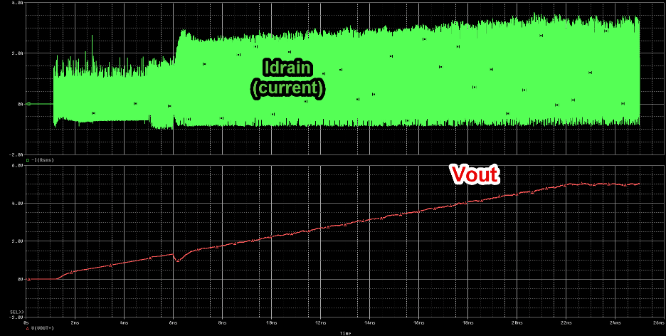
For comparison, here's what happens when the soft-start capacitor is too small (0.1µF instead of 0.47µF):
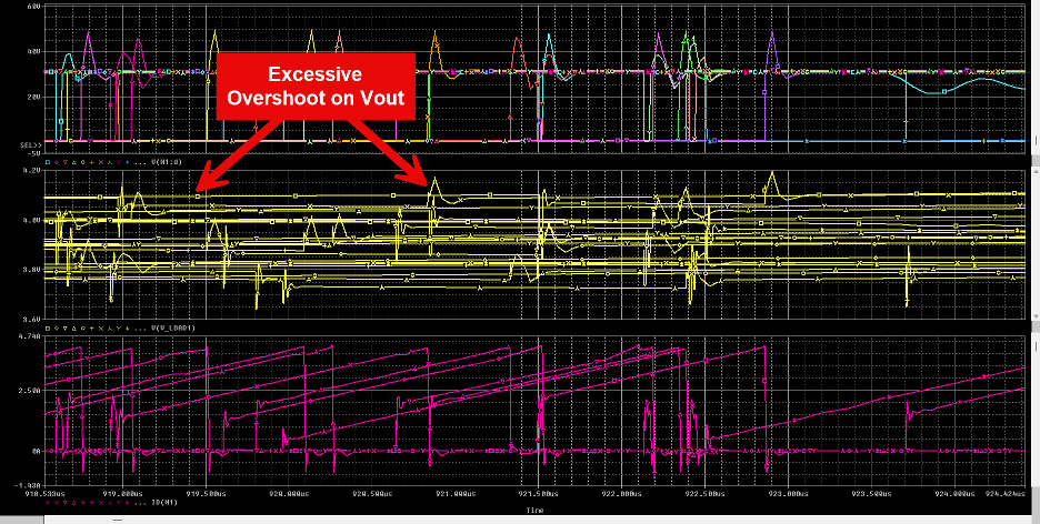
Startup Ramping up and causing overshoot
The output ramps to 5V in just 4ms instead of 13ms. Sounds like an improvement, right?
Except: the output overshoots to 5.8V before settling back. The switch current spikes to 2.9A during the ramp-70% higher than necessary. And the output rings for 30ms before the loop fully stabilizes.
That 5.8V overshoot might be fine for a phone. But if this adapter powers a microcontroller with a 5.5V absolute maximum rating, you just shortened its lifespan-or killed it outright.
The Burden - Understanding Startup Load Challenges in Power Supplies
"Burden" refers to the load the power supply sees during startup. Different loads create different startup challenges:
|
Startup Scenario |
Description |
Key Risks |
|
No load |
The output rises quickly because there's nothing drawing current. |
Risk of overshoot if soft-start is too aggressive. |
|
Full load from t=0 |
The output rises slowly because current is being drawn immediately. |
Risk of the supply not starting if the load exceeds the soft-start current limit. |
|
Load step during startup |
The device waits for power-good, then suddenly draws full current. |
Risk of output dip or oscillation if the loop isn't settled. |
The simulation lets you test all three scenarios. For USB-C adapters, I typically simulate no-load startup (worst case for overshoot) and a load step at 90% of nominal voltage (testing the loop's ability to handle the transition).
The Takeaway
Startup isn't a moment-it's a sequence of events that all need to go right. The inrush current needs to stay within component limits. The soft-start needs to ramp the output without overshoot. The control loop needs to stabilize before the load shows up.
PSpice simulation lets you watch this sequence unfold before you build hardware. You can tune the soft-start capacitor, verify the inrush limiting, and test worst-case load scenarios-all without blowing a single fuse or stressing a single component.
For a 10W USB-C adapter, getting startup right means the difference between a product that works reliably for years and one that fails intermittently in the field.