The Role of Control Loops in Stable Power Supplies
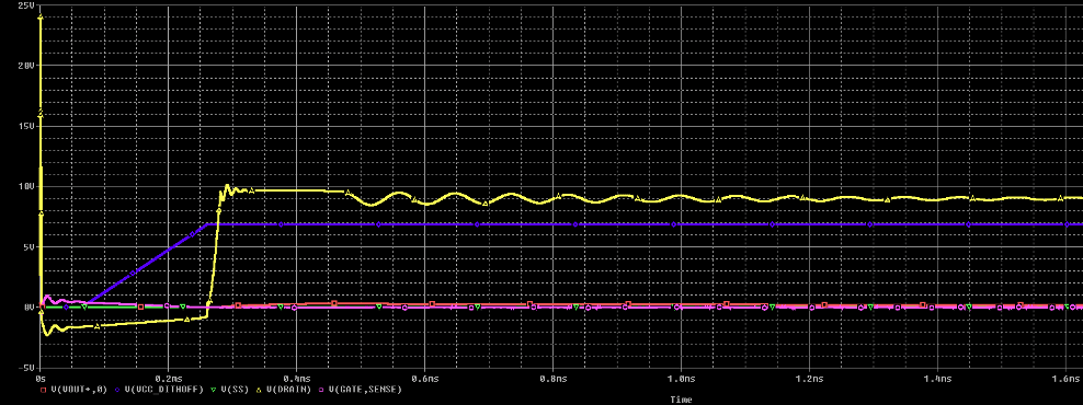
Figure 1: Vout of a Flyback Converter Oscillating Until Settling
Have you spent hours or days learning about that Flyback converter, selecting the right chip, becoming a power electronics expert in a week, only to still see ringing and noise on your oscilloscope without knowing why?
For many new power converter designers, this scenario might sound all too familiar: You meticulously follow the design guide, double-check your calculations, and even simulate the circuit. Yet, when you test the design, you’re met with unexpected ringing.
You’re not sure if it’s the design itself, the chip or the PCB layout. And frankly, you don’t have time to figure it out. So you stay late to find the issue, make changes on the layout and still get the same problem.
The problem could be anything really, but often when there’s ringing, or poor output voltage recovery, the culprit could be the control loop.
If you want to better understand why control loops in switching power supplies must be carefully designed to maintain stability, this on-demand webinar on the physics-based foundations of power supply design explains how switching behavior, energy transfer, and system dynamics influence phenomena such as ringing and transient response.
Why Control Loops are Often Overlooked
When power electronics are taught in university and books, they spend plenty of time on the power stage (i.e. Cin, Vin, MOSFET Drain, etc.).
But having specialized in control theory in graduate school, I noticed engineers and teachers would skirt over control theory, or do some fancy hand-waving at best. Sadly, this is where real-world failures are found and can’t easily be changed after PCB manufacturing. Understandable, since control is more abstract and also more confusing.
But you don't have to wait until the test bench to find out how a circuit will behave. During my power electronics control research days, I regularly made boards that had little to no ripple voltage (<1%) and astounding response to current jumps. How? With proper simulation and a proper understanding of control theory.
But first let's talk about the control loop.
What the Control Loop Is Actually Doing
Every regulated power supply is constantly answering one question: "How hard should I drive the power stage right now to keep VOUT where it belongs?"
The control loop measures something related to the output (voltage, current, or both), compares it to a reference to get an error signal, processes that error through a compensation network or digital controller, and adjusts duty cycle, frequency, or phase to push the output back toward the target.
If the loop is too timid, you get sluggish response and poor regulation under transients. If it's too aggressive, you get oscillation, overshoot, and sometimes catastrophic failures when real-world parasitics enter the picture.
The difference between a supply that works and one that doesn't often comes down to three numbers.
Key Metrics for Control Loop Performance.
You don't need a PhD in control theory. But you do need to understand these:
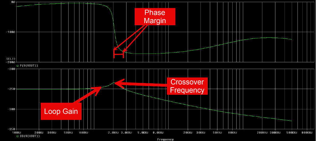
Bode Plot of ac analysis for Flyback Converter
Loop gain tells you how strongly the control loop reacts to an error at each frequency. You want high gain at low frequencies (tight DC regulation) and falling gain at high frequencies (don't chase every switching glitch).
Crossover frequency is where the loop gain magnitude hits unity (0 dB). It roughly sets how fast your supply can respond to changes. Too low and you're sluggish; too high and you're amplifying and chasing noise.
Phase margin is how far the loop's phase is from –180° at crossover. More margin means more damping and less overshoot. Too little margin means ringing—or outright oscillation.
Rule of thumb: 45–60° phase margin is the healthy range for most supplies. Below 30° and you're asking for trouble.
But here's where theory meets reality.
How Physical Design Affects Control Loop Behavior
From calculation, your converter should have 50° phase margin at a nice crossover frequency. In the lab, you’ll always find conditions that you couldn’t account for in calculation or ideal simulation.
Common simulation conditions include: output capacitors having equivalent series resistance (ESR) that shifts zeros and poles, transformer leakage and inductor dc resistance (DCR), resistor tolerances in the sensing circuit, parasitics in the layout that inject noise right into your feedback path, and digital loads (like a stepped current sink) that produce sharp sudden current loading (FPGAs, CPUs, AI accelerators).
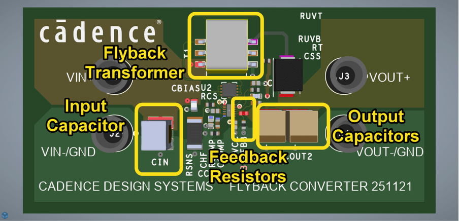
Flyback Converter PCB Layout
Even if the datasheet shows an application note with a specific circuit or typical compensation network, the specific way you lay out the PCB, the magnetics, and load can move the control loop behavior enough such that it creates a host of issues.
For example, subharmonic oscillations in the duty cycle, they double the pulses or jitter near the current limit, and startup overshoot of the Vout voltage. If you don’t use soft start, that can cause Vout to behave incorrectly.
This is exactly where simulation and measurement have to work together.
A Proven Workflow for Control Loop Optimization
Here's how to improve control loop behavior before you design another PCB:
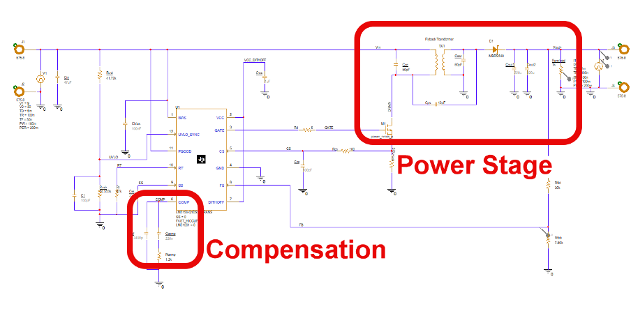
Flyback Converter Schematic (Non-isolated)
First, model the power stage. Use averaged models (PSpice power IC models or behavioral equivalents) for your topology. Include realistic parasitics: ESR, ESL, DCR, leakage inductance. The model doesn't have to be perfect—it has to be close enough to show you where the limits of the circuit are.
Second, add your planned compensation. Type II, Type III, or whatever your controller uses. If it's digital, model the equivalent transfer function.
Third, run loop gain analysis. Generate Bode plots of gain and phase under nominal conditions, then under worst-case: minimum input voltage plus maximum load plus high temperature. Check that crossover and phase margin stay in safe regions across all corners.
Fourth, verify with transients. Simulate load steps (10% to 90%, 50% ± 40%), line steps (VIN min to max), and startup/shutdown profiles. If the Bode plot looks good but transients ring, something in your model is off—find it now.
Fifth, correlate to the bench. Once hardware exists, inject small-signal perturbations (if you have the gear) and compare measured Bode plots to simulation. Adjust models where needed. That feedback loop—simulation to bench to better simulation—becomes an asset your whole organization can reuse.
Over time, you build a library of "known-good" loop designs for your standard topologies and controllers. That's when things start to scale.
Making the Power Design Process Scalable
As organizations grow, patterns emerge: one team owns the architecture, another owns the layout. Power stages get reused across product lines. Late-stage failures in EMI or transient testing get very expensive.
A mature power design process treats the control loop the same way software teams treat unit tests. Every new supply gets stability sims across corners—mandatory, not optional. Every reuse gets the control loop re-checked when load or layout changes. Every lab failure feeds back into the models and templates.
This is where integrated tools matter. Engineers shouldn't juggle five environments to reason about one loop. In a Cadence flow, you can sweep compensation components and see their impact on Bode plots, run Monte Carlo to see how tolerances affect stability, and combine loop gain analysis with stress checks—all before the design hits layout.
Then when you do go to layout, you verify that sense line routing won't inject noise into the feedback path, and you catch parasitic inductances that might alter dynamic response before they become bench mysteries.
The Real Lesson
The power stage is the part of the design you can see. The control loop is the part that determines whether it actually works.
Most "mystery oscillations" aren't mysteries at all. They're predictable consequences of a loop that wasn't checked across corners, or parasitics that weren't modeled, or a compensation network copied from a datasheet without verifying it fits your actual system.
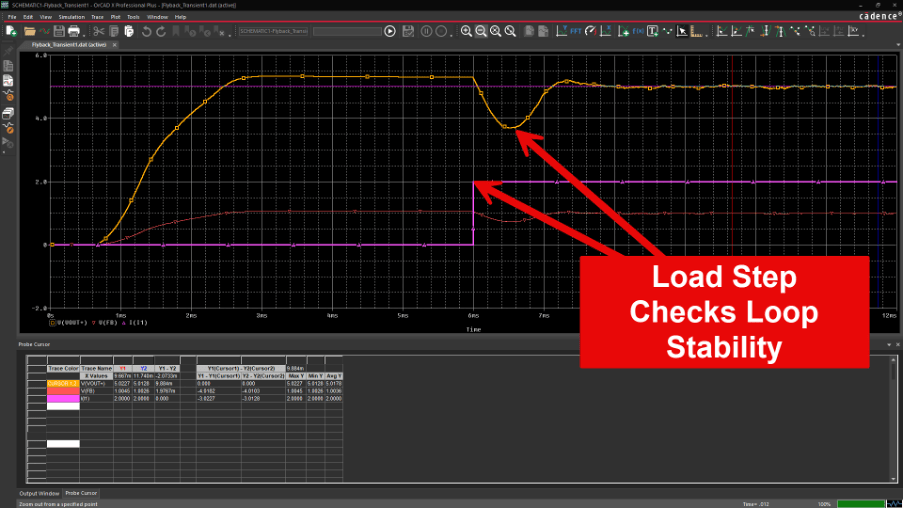
Flyback Circuit compensator response to a Load step at 2 Amps
Simulate before you manufacture the PCB Assembly. Check performance corners and outliers, not just nominal values and conditions. Build a library of validated loops. Feed your lab test bench results back into your models.
That's how you stop debugging control loops and start shipping stable power supplies.