01 - Exploring the Workbench Canvas With Topology Creation
This module covers exploring the Sigrity X Topology Workbench canvas and creating a new topology from scratch. Do the following steps:
- Open Sigrity X Topology Workbench in one the following ways:
- Start > Run and type TopWb
- Start > Programs > Cadence System Analysis (Product Version) > Sigrity X Topology Workbench (Product Version)
- In the Product Choices dialog, select Topology Explorer and click OK.
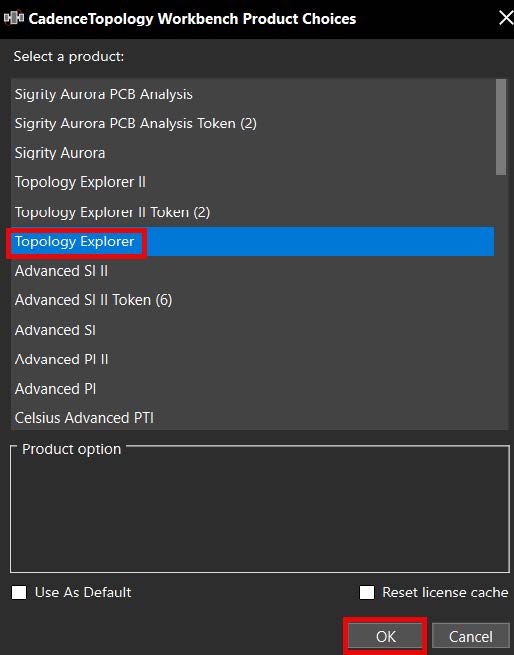
- The Sigrity X Topology Workbench window opens as shown below:
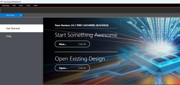
Click New under Start Something Awesome.
- The Create New Topology dialog appears as shown below.
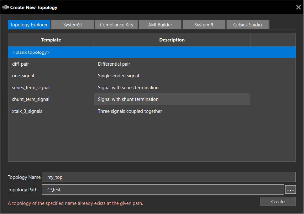
This dialog allows access to all capabilities in TopWb. Selecting options in the other tabs will relaunch the Product Choices dialog.
There are currently four methods of topology creation. The first and second methods are available in the Create New Topology dialog.
- From scratch (the “<blank topology>” template row)
- From a template (one of the named template rows)
- From old formats (.ssix and .top files with the Open or Open Recent links under Get Started)
- Extract from Allegro
In the Create New Topology dialog:
- Enter a name in the Topology Name field.
- Verify the directory in the Topology Path field.
- Select the <blank topology> row.
- Click on the Create button.
- The Sigrity X Topology Workbench canvas is designed to have a minimalistic layout with a few symbols and panes on the left and right sides of the canvas. Additional dialogs open at the bottom as needed.
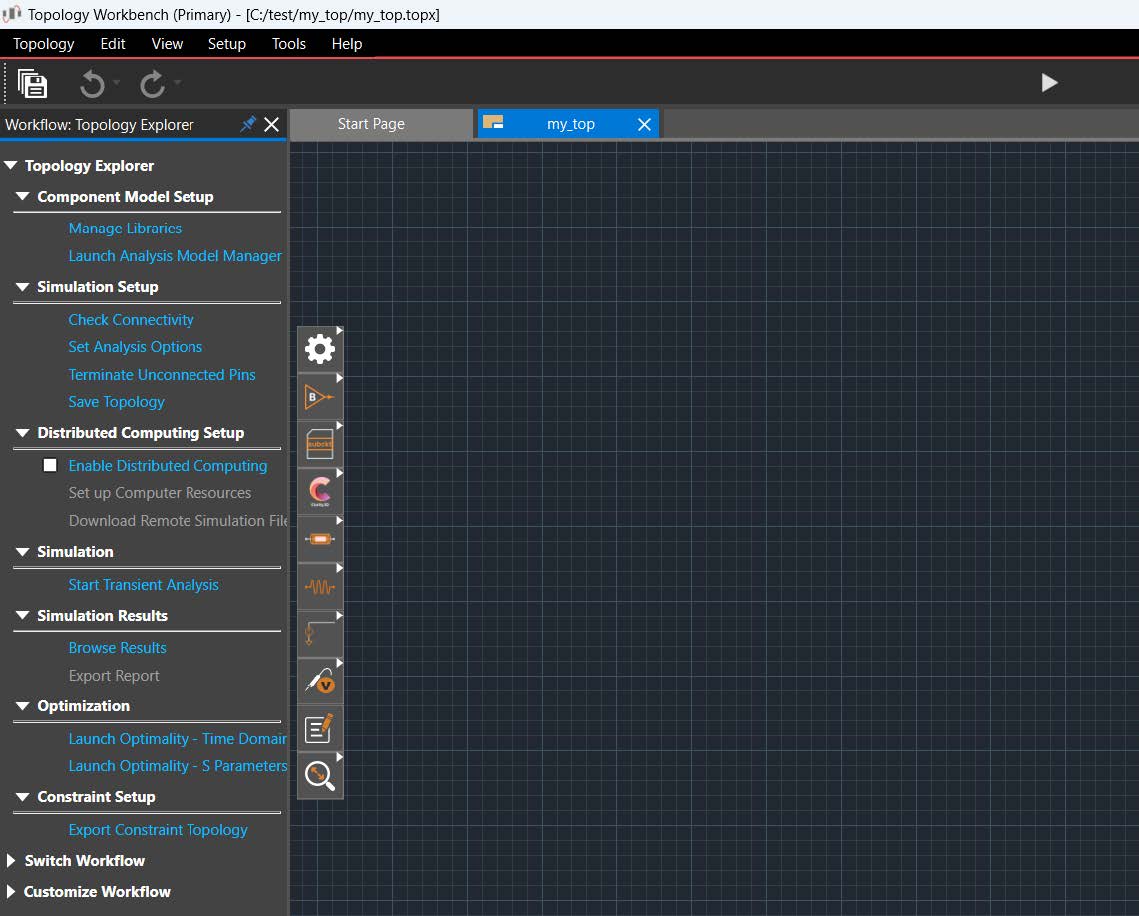
- Select View > Command Window from the main menu.
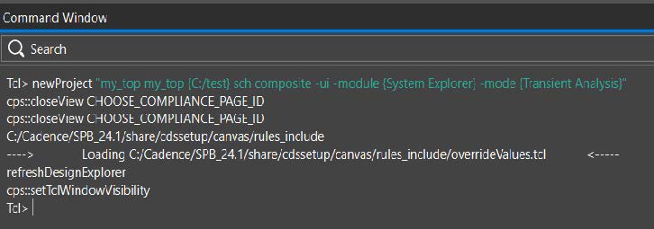
Sigrity X Topology Workbench supports the Tcl scripting language. This window can also be accessed with the Command Window symbol in the lower-left side of the main window.
- Click on X in the upper-right corner of the dialog to close the window.
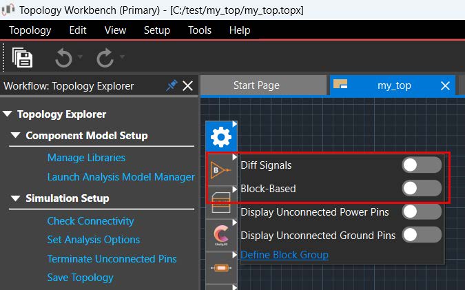
- Make sure both Diff Signals and Block-Based are unchecked in the Add Block pane.
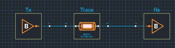
- Build a topology by using the following elements:
- Transmitter (IBIS)
- Trace
- Receiver (IBIS)
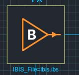
The IBIS blocks have a B mark on them.
Select one block at a time. After you finish, your topology should look like the following:
With both check boxes disabled in the Add Block pane, the connectivity is single-pin-based, just like SigXplorer, and requires no MCP to define the connectivity.
- Simulate by picking the Start Transient Analysis button at the top-center of TopWb.
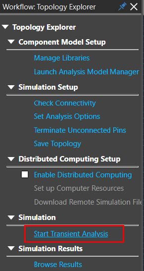
All blocks have default models associated.
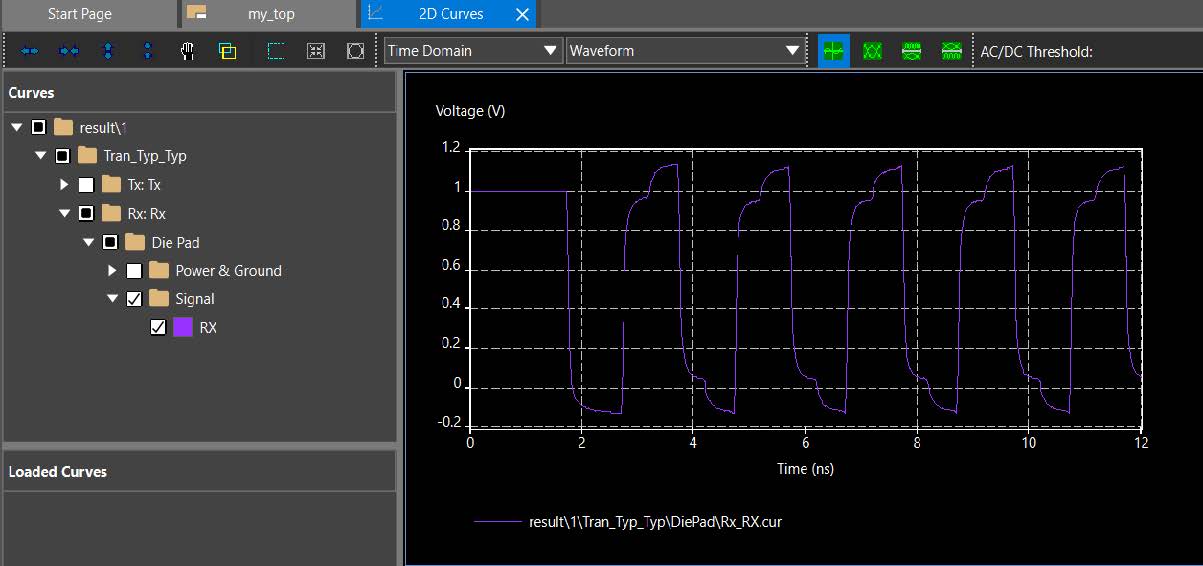
The waveform viewer looks like 2D curves, but it is a different .exe file and has additional capabilities.
- Close the waveform viewer window.
- Double-click on the Tx block. It will open Edit Properties window.
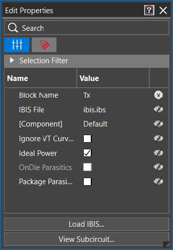
This will display the block properties in the Properties pane. This method simplifies the use model. Notice the default IBIS model and the button to access the subcircuit at the bottom.
- Click on the last column of the IBIS File row and select Name and Value.
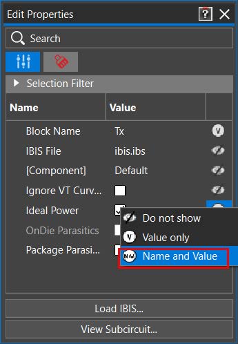
The symbols in this last column indicate visibility on the canvas and give you control over what gets annotated.
- Right-click on some blank part of the canvas.
- Select Display Unconnected Power Pins.
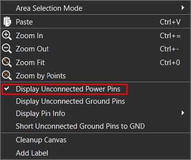
- Right-click again and select Display Unconnected Ground Pins.
Both “display” options should now have a checkmark and you will see the exposed power and ground nodes (as appropriate) on each block.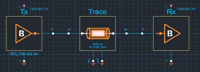
- Right-click on the ground pin for the Tx block and select Short to GND.
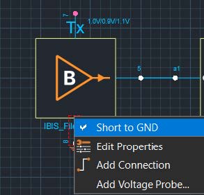
Visually, this is equivalent to not exposing the pin. Pins can be connected directly to the ground with an automatic symbol added or connected through any desired path.
- Right-click on the Tx power pin and select Connect to Power Supply.
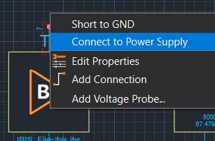
A range of values is added to the pin.
- Double-click on the same Tx power pin just below the voltage values as shown in the screenshot in step 18.
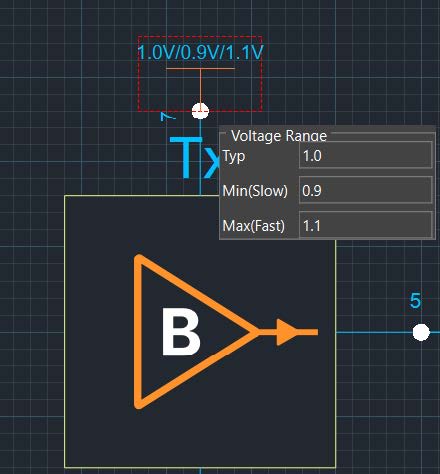
A selectable box lets you edit the values as shown in the Edit Properties pane. This lets you set the voltage range for a block.
- Select everything on the canvas by dragging a window and press the Delete key. This deletes the components placed and the associated connectivity.
- Select the Block-Based check box in the Add Block pane. Any new block added will have MCP-based connectivity.
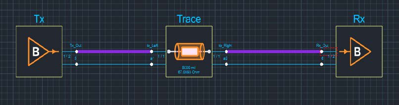
- Rebuild exactly the same topology (after reselecting the Add Block symbol):
- Transmitter (IBIS)
- W Element
- Receiver (IBIS)
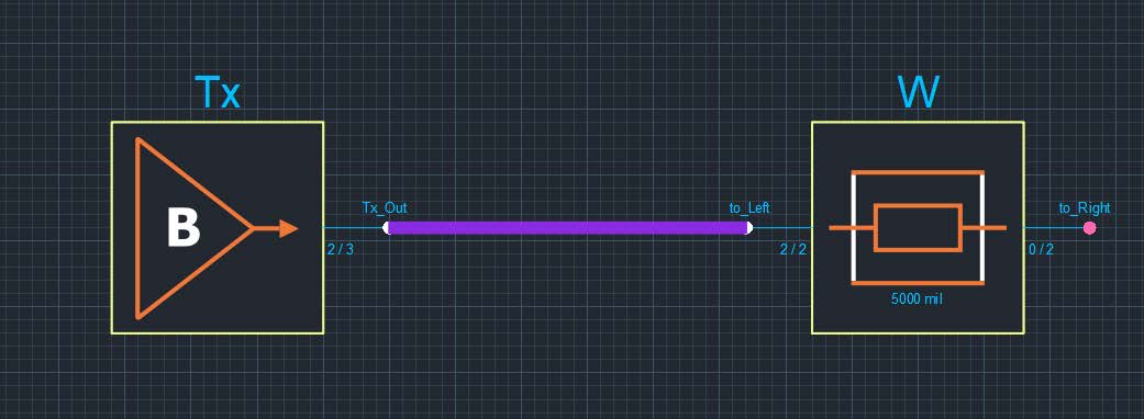
Notice the thicker connectivity lines and the number of connected / total connections indication at each pin.
- Double-click on one of the thick purple connectivity lines.
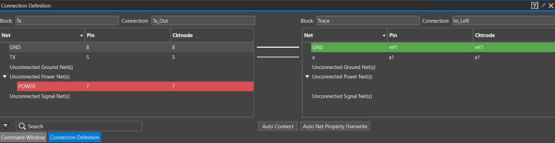
This is the MCP connectivity pane.
- Click on X to close the Connection Definition pane.
- Double-click on the pin on the Tx block.
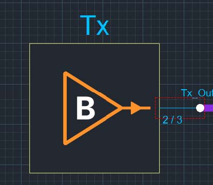 This opens the pins in the Edit Properties pane.
 - Right-click on the Tx pin and select Remove Selected Pin(s).
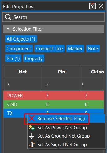
- Repeat the process for the pin on the other side of Trace (remove the pin “a”).
Now, this topology has a mix of single-pin and multi-pins. This is just some of the available customizations to have a mix of hierarchy in the canvas. You might also go the other way.
[Optional] Delete all connecting lines on the canvas by selecting them and pressing the Delete key. Now, move the element, W, up and out of the way. Connect Tx and Rx by overlapping the pins and move them back into the positions illustrated above. Place W on top of the existing interconnect. As long as the pins match, the new connections will be made. Getting Started with Topology Workbench for Topology Creation and Extraction Using Constraint Manager: RAK
- Select the single pin on the Tx block and slide it back to the upper pin.
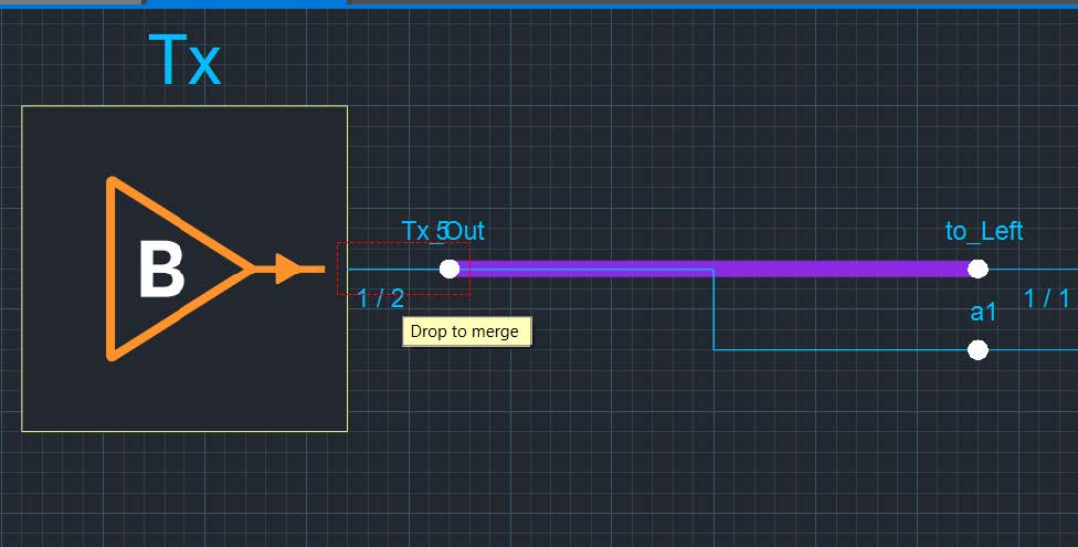 This will merge the pins as a single multi-pin.
 - Exit Sigrity X Topology Workbench without saving.
View the next document: 02 - Pre-Layout Topology Extraction and Constraint Export
If you have any questions or comments about the OrCAD X platform, click on the link below.
Contact Us