02 - Pre-Layout Topology Extraction and Constraint Export
The other key aspect of Sigrity X Topology Workbench is the integration with the constraint-driven flow of Allegro. Majority of the existing SigXp users use it for the constraint generation portion with no simulation. There are multiple use models but the most common is extracting a topology from an existing design – schematic or layout.
In this module, you will learn:
- How to extract a topology from Constraint Manager on an unrouted board
- How to use this topology to create a constraint set for the board.
Do the following steps:
- Select Start > Programs > Cadence OrCAD X and Allegro X (Product Version)> PCB Editor (Product Version)
- Open the prelayout_Module1.brd file from the lab folder attached with this RAK.
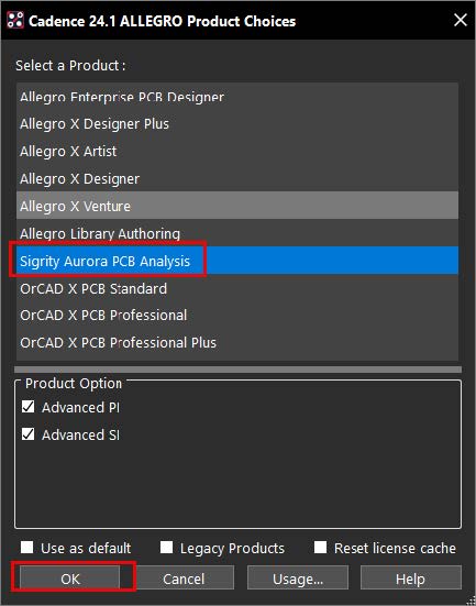
- Select Sigrity X Aurora PCB Analysis in the Product Choices dialog.
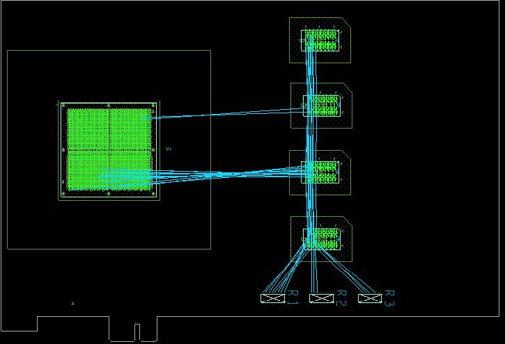
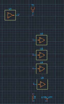
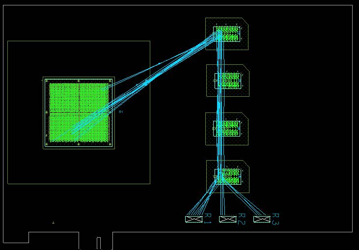
This design has just the “rats” turned on for the address bus. You can see that they are not scheduled in a fly-by technology. You might not like the default algorithm based on the shortest connection distance.
- From the main menu, select Setup > Constraints > Constraint Manager.
- In Constraint Manager, open the Electrical domain. Select Net > Routing > Wiring.
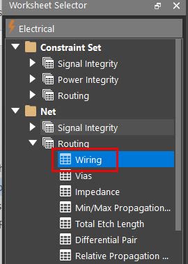
You might have more workbooks in your Worksheet Selector depending on your license.
- Using Tools > Options, open the Options dialog from CM.
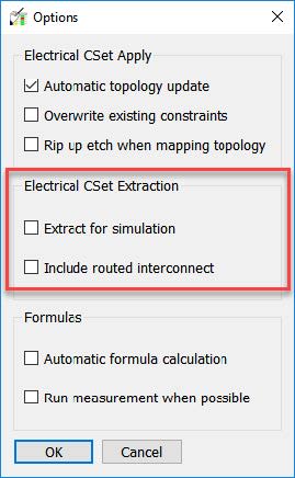
The highlighted section in the above screenshot controls the topology extraction from Constraint Manager for both SigXp and TopWb.
- For both topology editors, Include routed interconnect controls how interconnect models are extracted, and the results are same for both editors.
- For SigXp, the Extract for simulation option controls whether device models are passed to SigXp. For TopWb, this option controls which tab will be populated in TopWb.
SigXp has a single canvas that is used for both simulation and constraint capture. Sigrity X Topology Workbench has separate canvas tabs for simulation and constraint capture.
- Make sure that both options in the highlighted Electrical ECSet Extraction section are disabled. Click OK.
- Scroll back to the top of the Objects column in Constraint Manager. Right-click on the ADDR(15) net class but do not select anything.
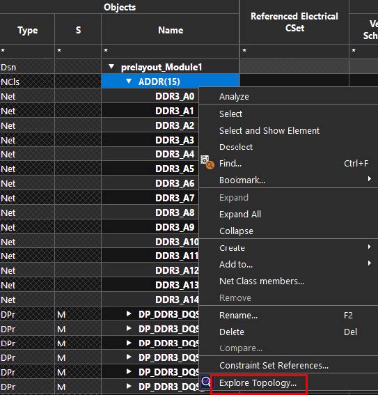
Notice that Explore Topology is the only option.
- If you do not see Explore Topology, enter the set use_topwb_for_sigxp command in the Allegro Command window:
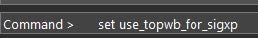
This variable makes Sigrity X Topology Workbench available in the appropriate menus for topology extraction.
- Choose Topology Workbench if prompted for a product.
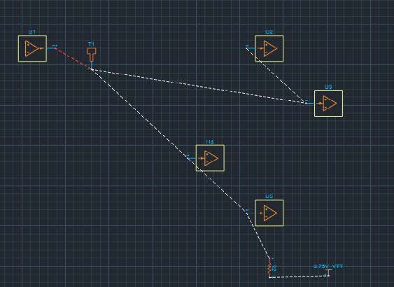
Your wiring might look different than what is shown above. Notice that there are no tline elements. As both options in the CM menu for extraction were “off,” the topology was extracted to the ECSet tab.
Adding constraints
- Select Set Topology Constraints from the workflow.
- Right-click on a blank part of the canvas and select Delete All Wires.
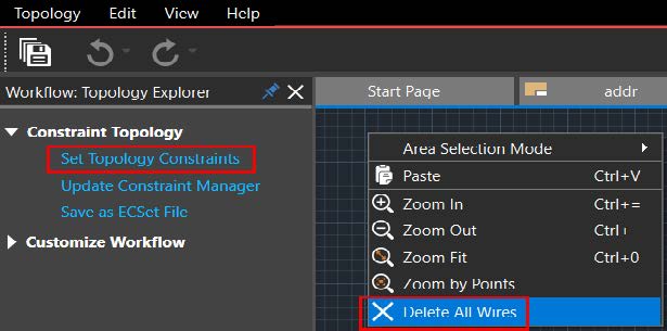
This can be done manually but before rewiring a topology to set the desired net schedule, it is sometimes easier to just delete all existing connections.
Rewire the pins based on the new placement.
Make sure that there is a green ball at the start and end of each connection. Also, make only pin-to-pin connections. Your canvas should look like the following:
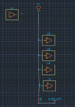
This is the desired “fly-by” schedule. - Select Update Constraint Manager in the workflow.
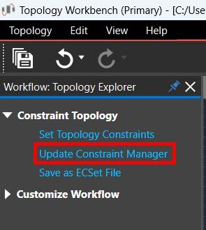
- Click on Yes in the following dialog to assign the topology to the entire class.
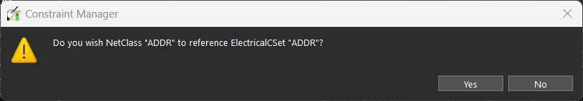
Extracting a topology at the class level means that it can be easily applied to all members of the class after it has been constrained.
- Close Sigrity X Topology Workbench without saving.
- Notice the change in the ratsnet lines in the Allegro canvas.
The ratsnets have now been reordered to the desired fly-by topology.
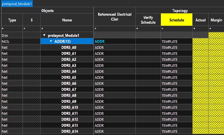
Some of the constraints you passed from Sigrity X Topology Workbench look like the above image in Constraint Manager. The yellow column header indicates that DRC is disabled for a check. Yellow cells in the worksheet indicate that pass or fail cannot be determined, which is because the DRC check is off. At this point, there is no benefit of verifying the routing constraints on an unrouted design.
- Click on X to close Constraint Manager.
View the next document: 03 - Post-Layout Routed Interconnect Extraction and Constraint Export
If you have any questions or comments about the OrCAD X platform, click on the link below.
Contact Us