08 - Validating the Design
This section covers how to use the 3D analysis and report generation functions to validate the routing and placement of the board design to make it ready for manufacturing.
OrCAD X Presto has a built-in 3D visualization capability that lets you preview the board design at any time during the design process. You can open the design in 3D and verify the design as a complete assembly. To analyze a design, 3D models must be assigned to all the symbols. You can map a 3D model either at a symbol level or at the design level. For the components used in this tutorial, 3D models are mapped with symbols.
Analyzing the Design in 3D
To do 3D analysis of a design, follow these steps:
- Choose View – Panels – Visibility to open the Visibility panel.
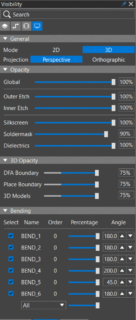
- In the General pane, switch the display mode from 2D to 3D.
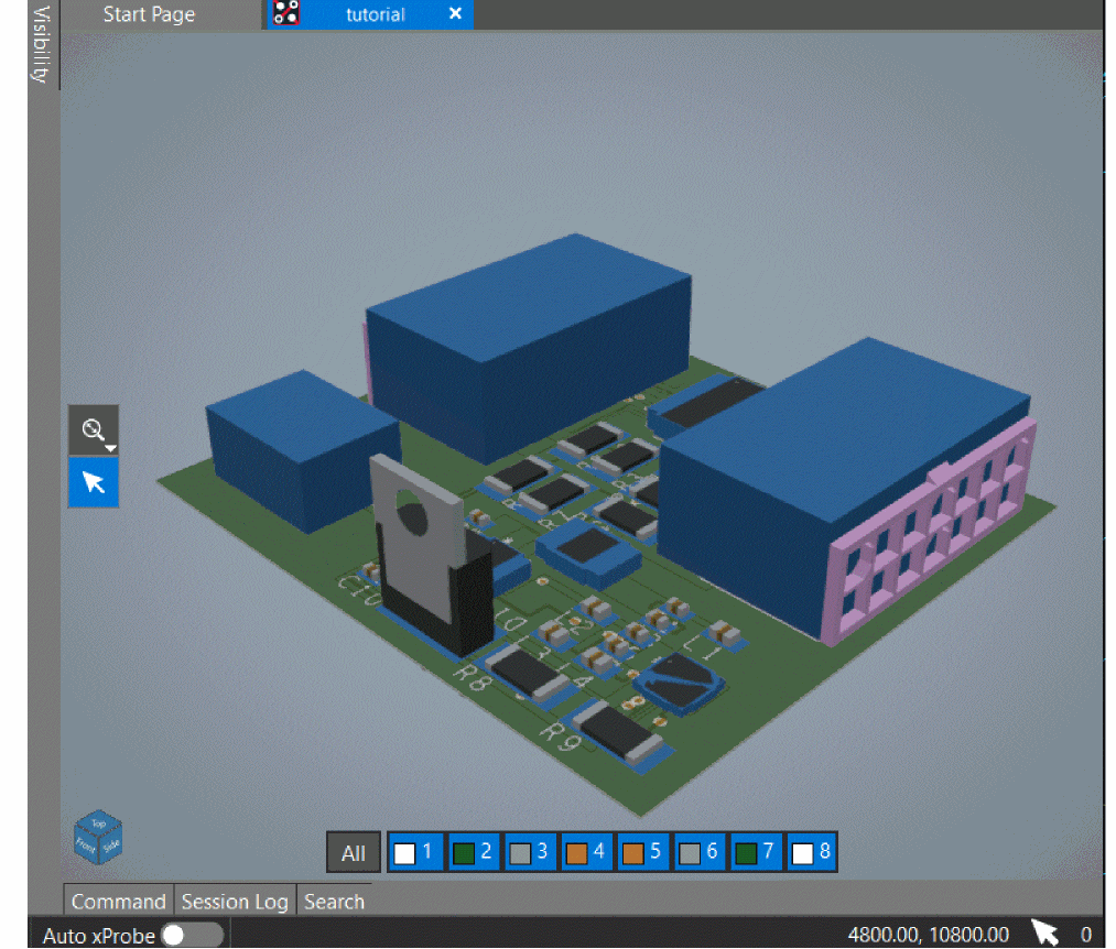
- OrCAD X Presto generates the 3D view of the active design and loads it under the design name tab of OrCAD X Presto.
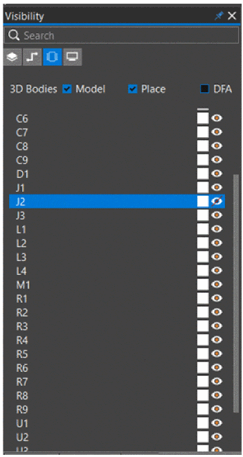
- To control the visibility of symbols, open the Component pane of the Visibility panel.
The symbols are listed under the layer names.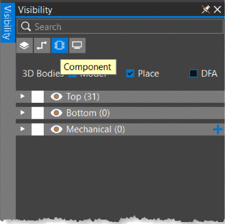
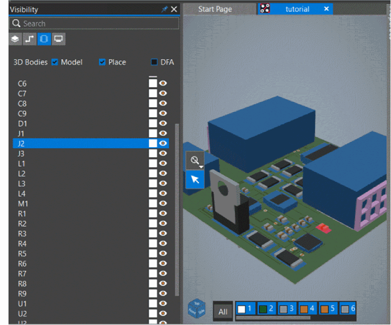
- Expand Top to view the symbols in the TOP layer, and toggle the visibility for J2.
- Click the 3D cube to choose camera options from the shortcut list for analyzing the design in different perspectives.
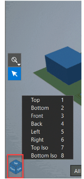
- Click anywhere or press Esc to hide the shortcut list.
- Click the layers toolbar to show and hide design layers while reviewing the design.
Generating Reports
You can generate reports to extract design information from the board design. To generate reports in OrCAD X Presto, do the following:
- Ensure that you have switched back to the 2D display mode.
- Choose Manufacturing – Export to Manufacturing.
- In the Exports dialog box, select the PCB Design Report check box.
- Ensure that Summary Report, Unconnected Pins Report, Etch Length Report, and DRC Report are added.
- Remove Database Diary Report from the list using
 control.
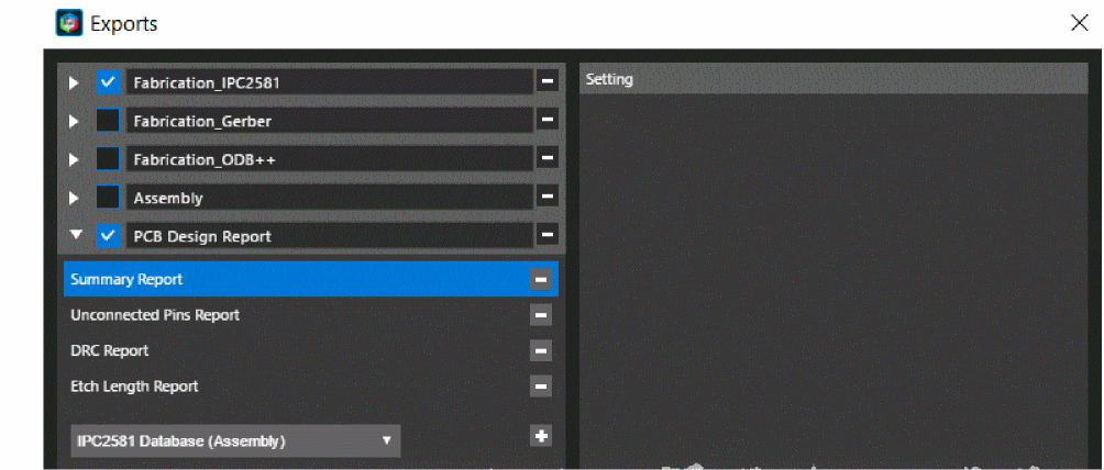
- Deselect the Create Archive option.
- Click Export to generate reports.
A confirmation message appears informing that the current Gerber layer definitions will be replaced with new definitions. - Click Yes to proceed.
A progress bar is displayed: Reports are generated in the fan_module_PCB Design Report folder in the working directory.
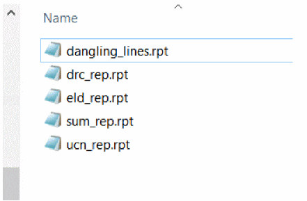
- Open the saved report in a text editor.
- Click Close to close the Exports dialog box.
- To verify the design status, check the Status pane in the Properties panel.
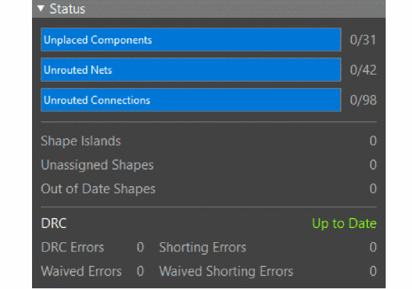
The status indicator for DRC is turned green and displays Up to Date.
Summary
This section covered the 3D analysis and report generation functions for validating the routing and placement of the board design to make it ready for manufacturing.
View the next document: 09 - Exporting Manufacturing Output
If you have any questions or comments about the OrCAD X platform, click on the link below.
Contact Us