07 - Routing Nets Interactively
Routing is the process of laying down the tracks to connect components on the board. Before connecting the components, you need to define the physical and spacing constraints.
Setting Up Constraints
You can define spacing and physical design rules within OrCAD X Presto using Constraint Manager. To route the tutorial design, follow these steps:
- Choose Tools – Constraint Manager.
The Constraint Manager window opens. - Click Physical and choose the All Layers worksheet in the Physical Constraint Set folder.
- In the worksheet, select the default physical constraint set and right-click and choose Create – Physical CSet.
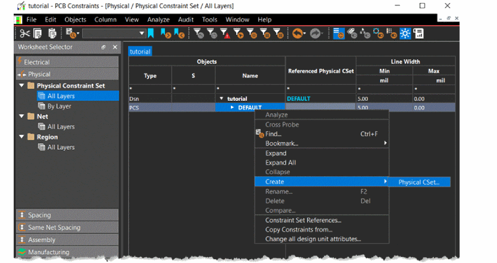 The Create Physical CSet dialog box is displayed.
 - Specify the name as POWER_NET_CSET and click Ok.
- Change the value of Min Line Width to 15 mil from 5 mil and Max Neck Length to 100 mil from 0 mil for both the TOP and BOTTOM layers.
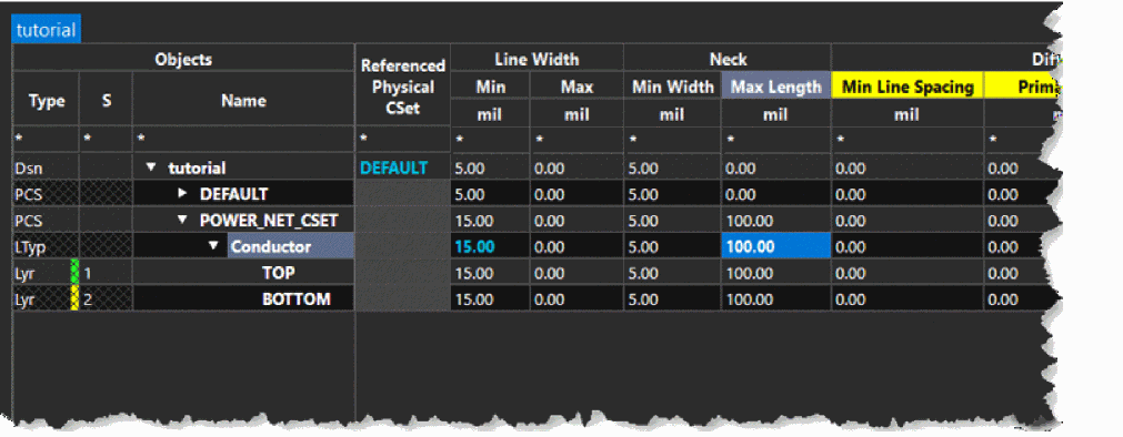 Changing values for the parent (Conductor) layer also changes the values in the child layers (TOP and BOTTOM) automatically.
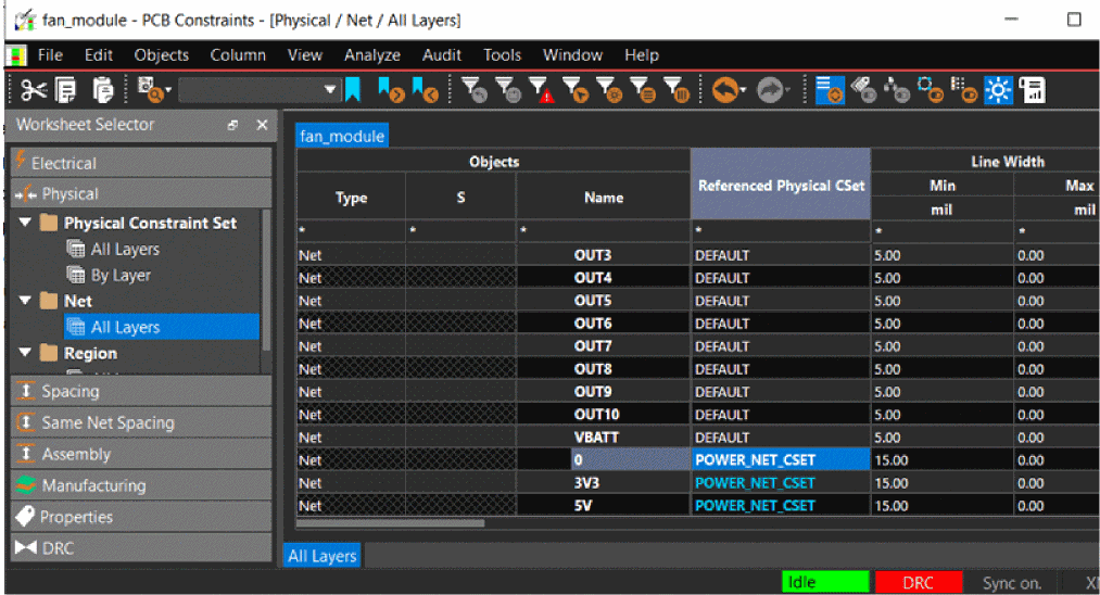
 - Choose Net – All Layers folder.
- In the All Layers worksheet, select the net 5V.
- Set the Referenced Physical CSet to POWER_NET_CSET.
- Similarly, select the nets 3V3 and 0 and set Referenced Physical CSet to POWER_NET_CSET.
- Choose File – Close to close Constraint Manager.
Assigning Color to Power and Ground Nets
Changing the visibility of power and ground nets makes them easier to route. To change the visibility of nets, follow these steps:
- Choose View – Panels – Visibility to open the Visibility panel.
- Expand the Nets pane and select the net 0 from the list.
- Click the color box associated with the net 0 and choose blue from the Presets.
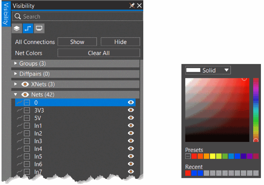 All the pins, vias, traces, and shapes that are connected to net 0are shown in blue on the design canvas.
 - Similarly, change colors for 3V3 and 5V to red in the Presets.
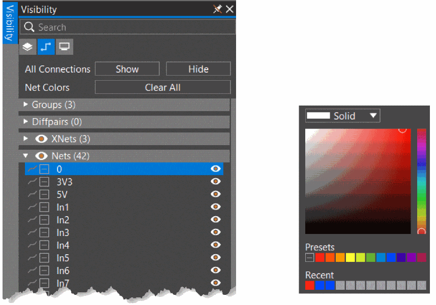 All the pins, vias, traces and shapes that are connected to nets 3V3 and 5V appear in red in the design.
 - Choose File – Save tutorial.brd to save the design.
Routing Design Interactively
You can route a design in the interactive mode using various options. To route the design in OrCAD X Presto, do the following:
- Click the Add Connect
 icon from the functional toolbar.
A pane opens, providing options for routing single connect lines (traces) and differential pairs. - Set the Route Mode to Manual.
- Set Trace Width to Constraint.
This setting takes the connect line width as defined in Constraint Manager. - Select a net to connect it to symbols, J3 and U2 and start routing.
The trace is added on the TOP layer. - To route the trace on the BOTTOM layer, double-click to insert a via.
- To adjust the route, click the Slide
 icon from the functional toolbar.
A pane opens with options to slide the traces. - Set the Slide Mode to Manual.
- Manually route all the nets in the design.
- Click the zoom fit icon
 from the functional toolbar to view the complete design.
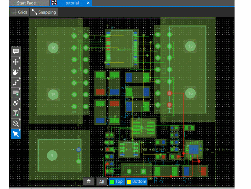
- To verify that all the nets are routed, check the design status for Unrouted Nets in the Properties panel.
- Choose File – Save tutorial.brd to save the design.
Renaming Components
After you have completed the placement and routing you can reorder the reference designators of components on the board in a specific pattern. This step makes the testing and assembly process easier.
- Choose Setup – Design Parameters Editor.
The Design Settings dialog box opens and displays Renumber Refdes page.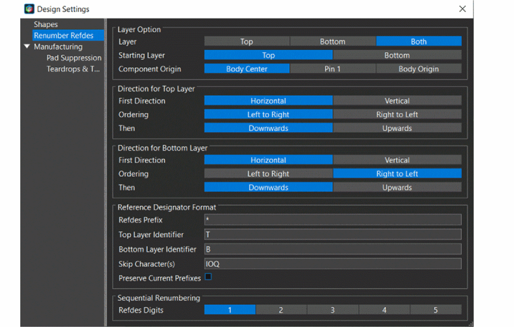
- In the Design Settings dialog box, make the following changes:
- Remove layer identifier for TOP and BOTTOM layers.
- Enable the Preserve Current Prefixes check box.
- Close the dialog box.
- Choose File – Save tutorial.brd to save the design.
Summary
This section covered the steps for setting up constraints required to route the board design and also introduced a set of routing commands to route the nets in a board design, interactively.
View the next document: 08 - Validating the Design
If you have any questions or comments about the OrCAD X platform, click on the link below.
Contact Us