Design for Reliability Tools With OrCAD X
Key Takeaways
-
OrCAD X enhances design accuracy, reducing errors through real-world assembly visualizations.
-
DFM and DFA rules integrated into real-time checks ensure efficient manufacturing and assembly, boosting reliability.
-
Powerful SI analysis tools in OrCAD X identify issues like impedance and coupling in high-speed designs.
Using OrCAD X DFM rules is one step in creating reliable boards.
Ensuring the reliability of printed circuit boards (PCBs) is more critical than ever. To address the challenges of meeting performance requirements and manufacturing constraints while ensuring board quality, users should keep design for reliability in mind. OrCAD X offers a comprehensive set of features and capabilities designed to ensure PCB reliability. Read on as we discuss design for reliability tools, starting with recently improved capabilities in OrCAD X 24.1.
OrCAD X 24.1 Updates Provide Improved Design for Reliability Tools
|
Feature |
Description |
Application to Reliability |
|
3D ECAD-MCAD Collaboration |
Enhanced 3D engine for ECAD-MCAD collaboration, enabling better design accuracy |
Helps ensure design accuracy by visualizing real-world assembly, reducing potential errors. |
|
Constraint Management |
Supports setting up design constraints to manage signal integrity |
Improves reliability by ensuring electrical compliance and reducing risk of signal degradation. |
|
Design Data Management |
Unified design documentation and data management system |
Ensures traceability and consistency, reducing errors due to miscommunication. |
|
Advanced Simulation Tools |
Supports simulation for thermal, signal, and power integrity analysis |
Detects and mitigates issues early, preventing failures related to thermal or signal integrity. |
|
DFM Checks |
Advanced manufacturability checks before production |
Increases the likelihood of successful manufacturing by preventing issues that could lead to failure during production. |
|
HDI and Miniaturization Support |
Enhanced design capabilities for high-density interconnects (HDI) |
Ensures reliability by supporting compact, high-performance designs without compromising signal quality. |
|
Signal/Power Integrity Tools |
Enhanced tools for assessing signal and power integrity |
Ensures reliable high-speed designs by addressing issues such as noise, cross-talk, and power delivery. |
|
Thermal Analysis |
Integrated thermal analysis tools |
Identifies potential overheating issues, ensuring component reliability under thermal stress. |
Design for Manufacturing (DFM) Checks Ensure Reliability
Design for Manufacturing (DFM) checks ensure that a PCB design can be manufactured efficiently and without errors. These checks validate that the design adheres to the fabrication capabilities and limitations of manufacturing processes. Potential issues that this tool can address include:
-
Insufficient spacing,
-
Thin solder mask dams,
-
Improper trace widths
Engineers can prevent these problems using DFM checks enhancing yield and reliability.
OrCAD X Implementation of DFM Checks
OrCAD X integrates powerful DFM checking capabilities directly into the PCB design workflow through its Constraint Manager. The software provides an extensive suite of advanced constraints related to fabrication, accessible via the Manufacturing worksheet. Designers can apply Design for Fabrication (DFF) constraints to address issues like mask openings, copper spacing, and silkscreen clearances.
OrCAD X allows for real-time DFM checks with instantaneous visual feedback, highlighting potential fabrication problems such as narrow solder mask dams or vias under components. Additionally, the DFM Wizard simplifies the setup of manufacturing rules by allowing designers to create and assign rules based on IPC standards or specific manufacturer guidelines.
Design for Assembly (DFA) Rules
Design for Assembly (DFA) focuses on simplifying the assembly process of PCBs to reduce production time and costs while improving product quality. DFA rules address component placement, orientation, and spacing to ensure that automated assembly equipment can place components accurately and efficiently. By adhering to DFA guidelines, designers can minimize assembly errors and thus create more reliable boards.
OrCAD X DFA Features
-
Through the Manufacturing worksheet, designers can define package-to-package spacing rules based on component classifications, such as chips, ICs, and connectors.
-
The Constraint Manager allows for the creation of symbol classifications, enabling the assignment of specific spacing requirements between different classes of components.
-
Real-time DFA rule checking is integrated into the placement process, offering visual cues like bumpers and DRC markers to prevent violations. This functionality helps designers optimize component placement for assembly efficiency and reliability, ensuring that spacing and orientation meet the requirements of automated assembly processes.
Designers can also apply DFM rules in a region-based setup to accommodate specialized circuit elements with unique requirements, enhancing the PCB's assembly reliability.
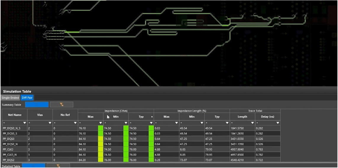
OrCAD X SI analysis allows for impedance calculations.
Signal Integrity (SI) Analysis
Signal Integrity (SI) Analysis is used for high-speed PCB designs where signal degradation can affect performance. SI issues such as reflection, crosstalk, and impedance mismatches can lead to data errors and system unreliability. By performing SI analysis during the design phase, engineers can identify and mitigate potential problems related to signal propagation.
SI Analysis in OrCAD X
OrCAD X offers integrated SI analysis tools that allow designers to evaluate and optimize the electrical performance of their PCBs.
-
Through the Workflow Manager, users can access impedance and coupling workflows to analyze characteristic impedance and potential crosstalk between traces.
-
The impedance workflow enables the examination of single-ended and differential impedance across nets, providing detailed reports and visualizations of impedance variations.
-
The coupling workflow assesses the coupling coefficient between traces, helping designers identify areas where crosstalk might be a concern.
These analyses are performed with minimal setup and can include all nets in the design for comprehensive evaluation.
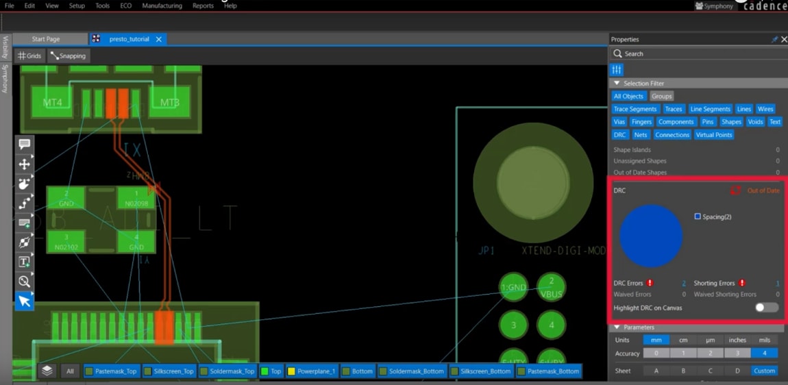
DRC status is reported in the pie chart within the OrCAD X Presto PCB Editor properties panel.
Design Rule Checks (DRC)
Design for reliability tools include Design Rule Checks (DRC) which are automated processes that verify a PCB design against predefined rules to ensure compliance with manufacturing and electrical requirements. DRC helps detect errors such as spacing violations, incorrect trace widths, and other layout issues that could compromise the reliability of the PCB.
OrCAD X DRC Capabilities
OrCAD X enhances the DRC process by providing a comprehensive and user-friendly environment for managing and correcting design errors through the Constraint Manager.
-
The software features a powerful interface where designers can define physical, electrical, and manufacturing rules tailored to their specific design needs.
-
Real-time DRCs provide immediate feedback as the design progresses, with visual indicators highlighting violations directly on the PCB canvas.
The Properties panel and search functionality allow for efficient browsing and filtering of DRC errors, making it easier to locate and resolve issues promptly. OrCAD X supports schematic-level DRCs in OrCAD X Capture, enabling designers to identify and fix errors before transitioning to the layout phase. This integrated approach ensures that designs adhere to all necessary constraints, significantly enhancing overall reliability and reducing the likelihood of post-production issues.
When it comes to design for reliability tools, leveraging the right resources is key to ensuring your electronics withstand the test of time. OrCAD X streamlines the process, helping engineers identify potential failure points early in the design phase. To learn more about how OrCAD X can support your high-reliability designs, explore Cadence's PCB Design and Analysis Software and discover the power of OrCAD X for your next project.
Leading electronics providers rely on Cadence products to optimize power, space, and energy needs for a wide variety of market applications. To learn more about our innovative solutions, talk to our team of experts or subscribe to our YouTube channel.