OrCAD X 3D Export and DFM Features
Key Takeaways
-
How to use the 3D export panel that supports a variety of file formats, including options for rigid-flex and bent designs
-
How to use the tools for adjusting the visibility of components and mapping 3D models to footprints
-
Introduction to OrCAD X 3D DRC capabilities that validates designs against 3D models within the database
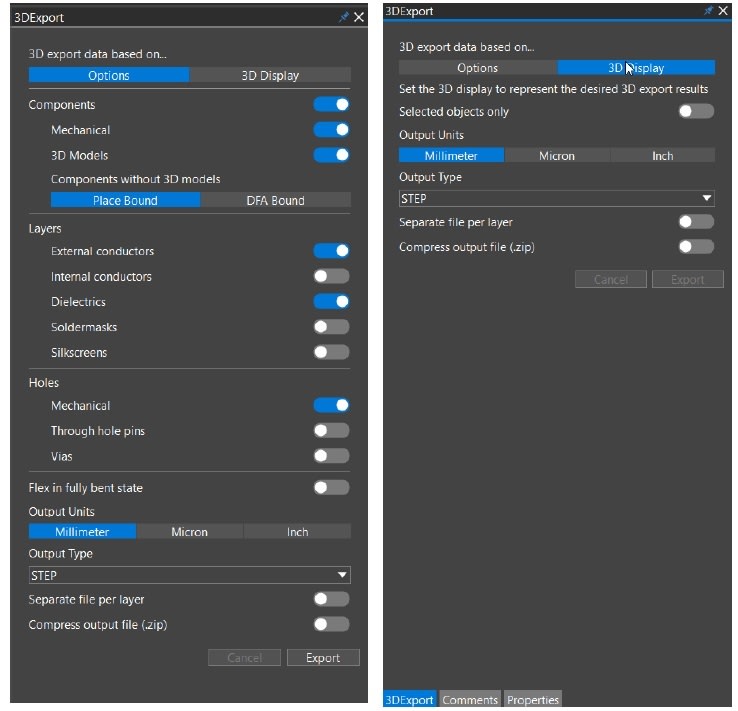
OrCAD X 3D Export Panel
3D Export Generation
Frequently, in order to view renders of your board, conduct MCAD analysis, design verification, thermal analysis, mechanical integration, or more, users may need to create a 3D export. With OrCAD X, this 3D design information can be outputted in a variety of file formats, including supporting 3D export for rigid-flex or bent designs. This export functionality allows for complete customization, facilitating exports according to whether the design is in a straight or foldable state.
How to Generate OrCAD X 3D Exports
|
Step |
Action |
Details |
|
1 |
Select File – 3D Export |
A docked 3D Export panel opens in a separate tab at the location of the Properties panel. |
|
2 |
Modify Display Options |
Adjust the options for 2D and 3D display in the Options and 3D Display tab. The 3D Display tab is functional only when the display mode is set to 3D in the Visibility panel. |
|
3 |
Enable Selected Objects (Optional) |
In the OrCAD X 3D Export Panel, you have the option to enable "Selected objects only" to output only the objects selected in the design canvas. |
|
4 |
Select Output Units and File Format |
In the OrCAD X 3D Export Panel: Output Units and Type, select the output units and the output file format. |
|
5 |
Export |
Select Export, and a file browser opens. |
|
6 |
Specify File Name and Path |
Specify the name and path of the output file and click the Save button. The output file contains the 3D representation of the design based on the visibility settings in the specified directory. It’s important to note that you cannot modify the display while the 3D export is in process. |
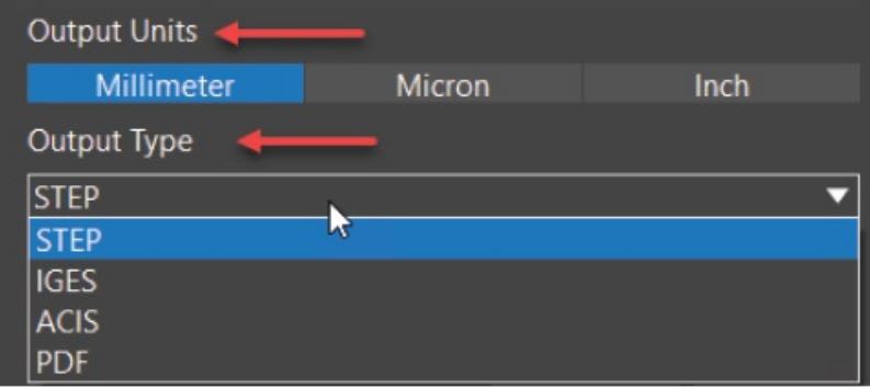
OrCAD X 3D Export Panel: Output Units and Type
OrCAD X 3D Environment Exploration - Component Shape Visibility
The OrCAD X 3D environment provides a platform for mapping 3D models onto footprints, viewing, and adjusting them. Located under the Components tab within the Visibility panel, users have the flexibility to modify the visibility of Place Bound or DFA Bound extrusions along with mapped 3D models. Users can also alternate between Opaque and Translucent states, allowing them to better visualize their design.
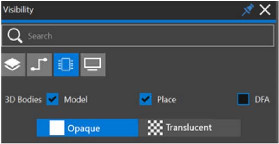
Visibility Panel Components Tab
Mapping 3D Models to Footprints
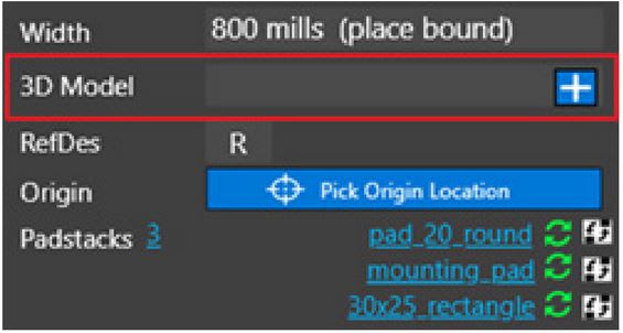
Text portion of the “3D Model” for a footprint is empty before importing.
Management of the footprint's associated 3D model is accessible via the primary "3D Model" field located in the property panel. If a a 3D model has not yet been linked to the footprint, follow the steps in the table below:
Modifying Footprint 3D model
|
Step |
Action |
Description |
|
1 |
Adding a New 3D Model |
Initially, the "3D Model" field appears empty. Utilize the plus (+) icon to initiate importing a new 3D model for the footprint. |
|
2 |
Import Process |
Click on the plus icon to open a file dialog. Navigate to and select the desired 3D model file. |
|
3 |
Model Integration |
Upon choosing a model file, it will be imported to the drawing at the origin point, with the 3D view refreshing to showcase the new model. Any import errors or warnings will be logged in the session log. |
|
4a |
Updating an Existing Model |
For an existing 3D model, the "3D Model" field displays the model's name. Use the "refresh" icon to update or replace the model by browsing and importing a new file, maintaining the existing model's mapping transform. |
|
4b |
Removing a Model |
To remove a 3D model and its mapping information from the footprint, click the minus (-) icon. |
![]()
When mapping a 3D model to a footprint, you have two icons available, refresh and minus, which are associated with steps 4a and 4b in the table above, respectively.
To adjust the mapping of a 3D model, you should utilize the "3D Location" accordion section within the properties panel, provided the footprint is linked to a 3D model. The tools for altering the mapping, such as alignment and rotation, become available when 3D view is selected and a 3D model is connected to the footprint. In this scenario, you will have access to the "3D Location" option.
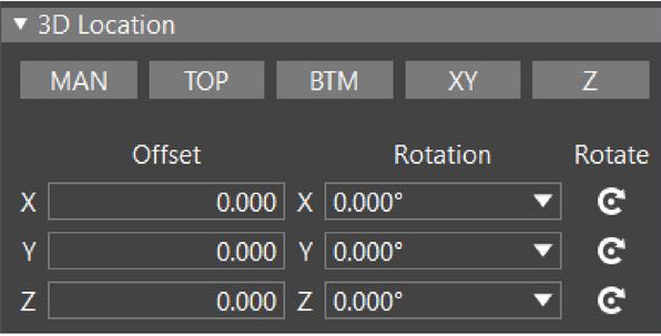
3D location option for alignment and rotation after mapping
OrCAD X 3D DRC Capabilities
OrCAD X also features an online 3D DRC (Design Rule Check) that validates designs against 3D models within the database, offering a robust tool for ensuring compliance with three-dimensional design rule checks, thereby streamlining the design verification process.
For example: if an LED conflicts with a mechanical object, moving the LED to resolve one conflict might trigger another DRC alert due to a different 3D obstruction. Importantly, it's not always necessary to view the 3D mechanical enclosure to identify such violations. However, visualizing the enclosure in 3D helps to clearly see issues like cutouts for the LEDs. Should a move result in a DRC error, the 3D DRC's alignment features can be employed to rectify the situation efficiently. Whether adjustments are made in 2D or 3D, the updates are live, ensuring the placement is always optimized and compliant.
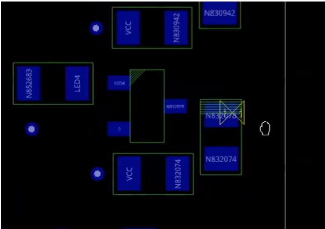
LED With 3D DRC violation on the right
Elevate your PCB design process with OrCAD X's 3D export functionalities, DesignTrue DFM technology, and comprehensive 3D Design Rule Checks. Sign up for a free trial today and transform your design workflow with the advanced features that set OrCAD X apart as a superior PCB design tool.
Leading electronics providers rely on Cadence products to optimize power, space, and energy needs for a wide variety of market applications. To learn more about our innovative solutions, talk to our team of experts or subscribe to our YouTube channel.