How to Create and Edit Library Component Categories and Subcategories in a Workspace?
How To
How do I create a new category of components in my library taxonomy and add symbols, footprints, and PSpice models to it?
Answer
To create a new category, follow these steps:
- Open a schematic design in Capture.
- Go to Place > Component. The Component Explorer window will open.
- Here, select the My Workspacenode and right-click and select Add.
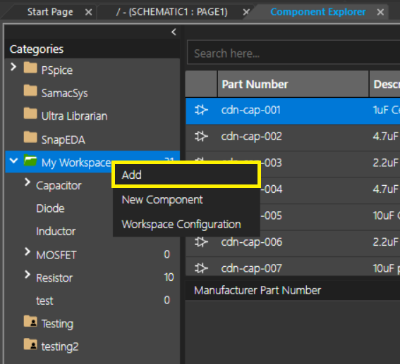
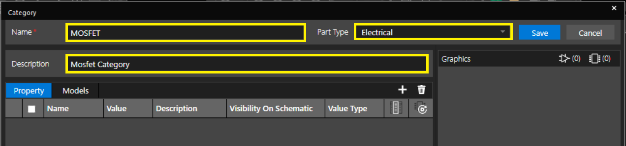
- This will open the Category dialog box. Provide the category name as needed.
- Select the appropriate part type from the dropdown menu and add a small description for the category as shown below:
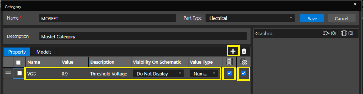
- Click on the + button in the Property tab section to add a row for the property.
- Provide the desired name, value, and description.
- Select the desired visibility in the Visibility On Schematic column and value type string/numeric in the Value Type column.
- Enable the Show in place component and Update on schematic checkboxes as needed.
The new category of part is created with the added property.
Now, follow these steps to associate a symbol to the created category:
- Click on the Modelstab and click on the clip icon and select Symbol to associate a symbol to the category.
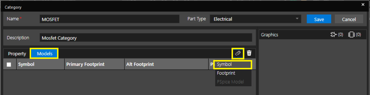
- This will invoke the Symbol dialog. Here, select the desired library and click on the Attach button to complete the symbol association.
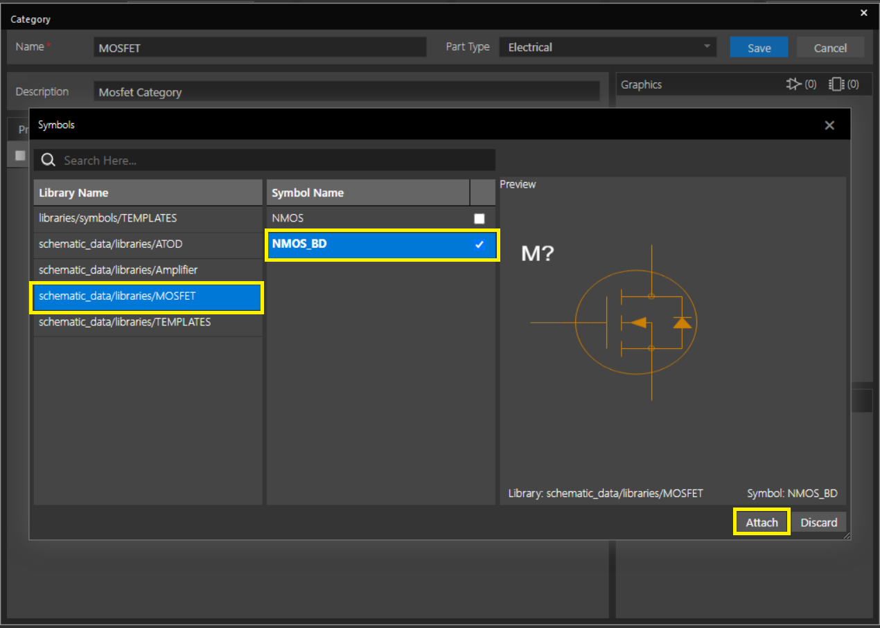
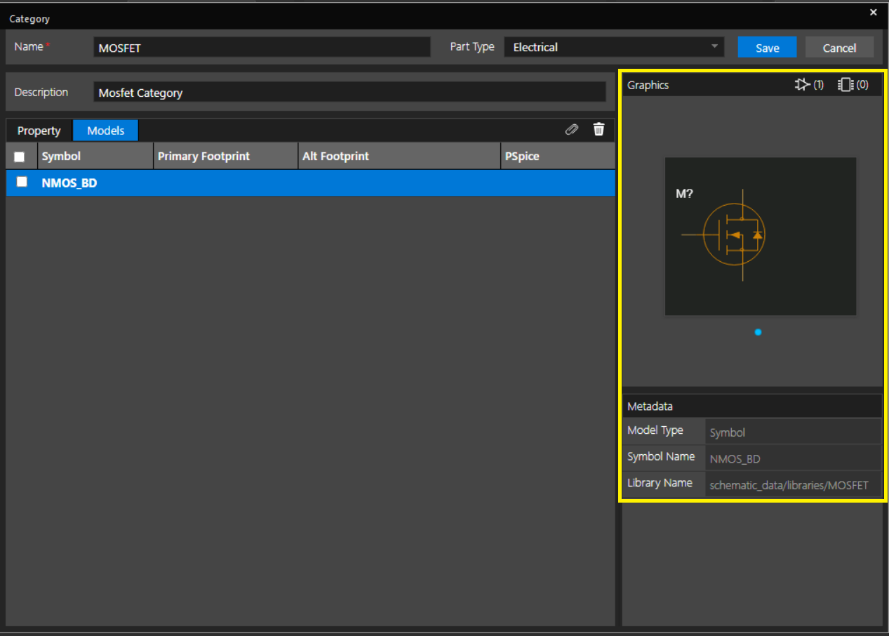
- The symbol preview along with its information is seen in the right section.
Similarly, you can associate the footprint and alternate footprint to the part category:
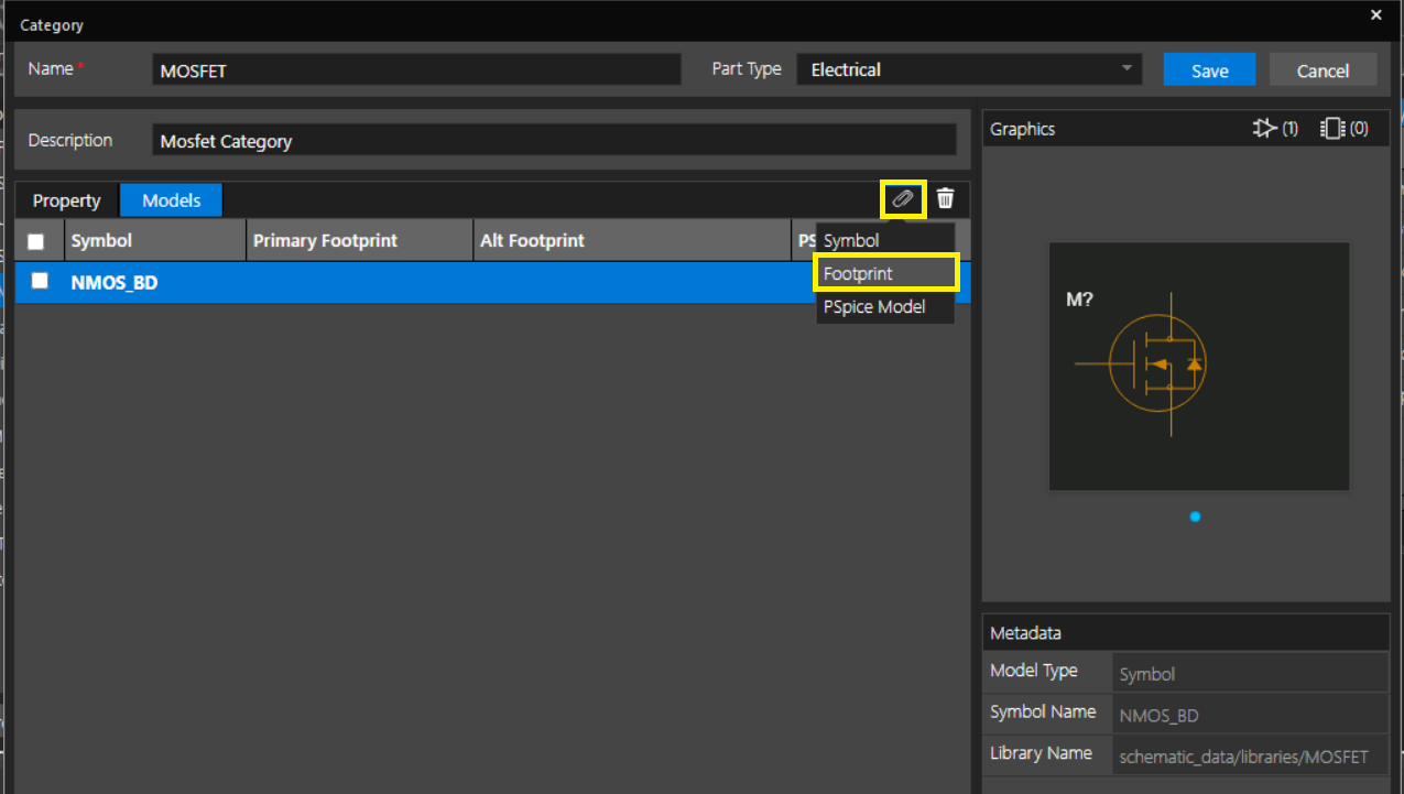
- In the Models tab, click on the clip icon and select Footprint. Alternatively, you can double-click on the individual cell entry under the Footprint section to launch the Footprints window.
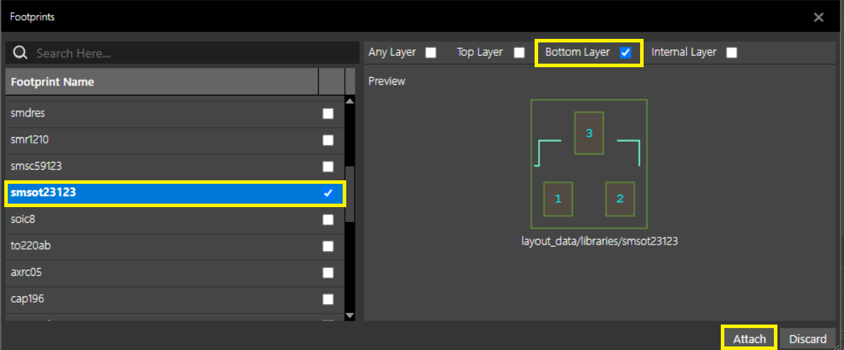
- This will open the Footprints dialog. Select the desired footprint. The first selected footprint becomes bold, indicating it to be the primary footprint.
- You can also assign the layer to the footprint by enabling the corresponding checkbox as shown below.
- Click Attach.
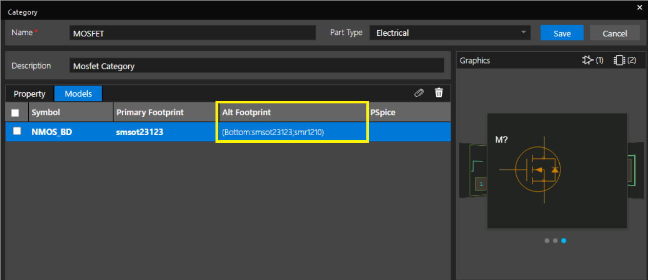
- All footprints selected after the primary footprint will be assigned to the ALT_SYMBOL property of the schematic instance. In the Component dialog, these will be seen under Alt footprintin the Models tab, asshown below.
Following similar steps, the PSpice model can also be associated to the part category:
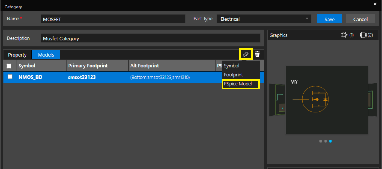
- In the Models tab, select the row of the symbol. Then, click on the clip icon and select PSpice Model. Alternatively, you can click on the individual cell entry under the PSpicecolumn to launch the Associate PSpice dialog.
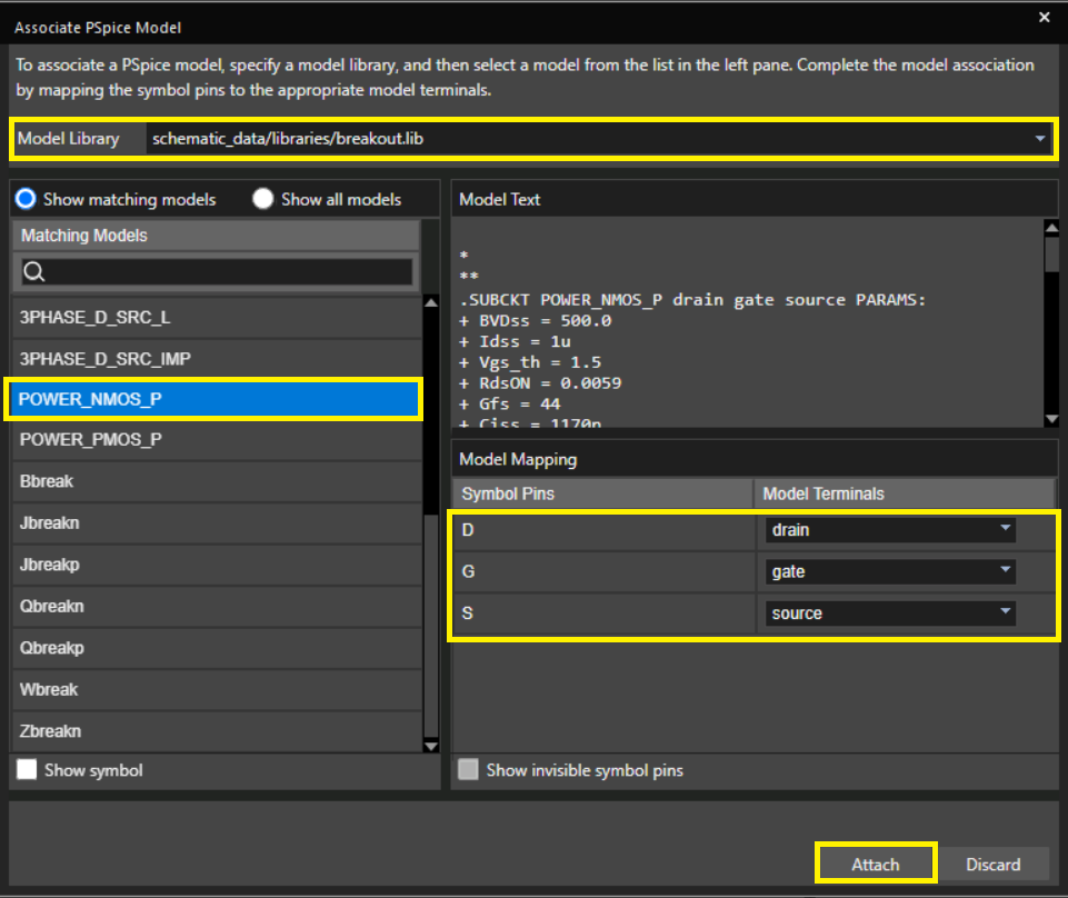
- From the Model Library dropdown, select the lib file and from the list of matching models, select the model.
- Now, under the Model Mapping section, map the symbol pins to model terminals. Click Attach.
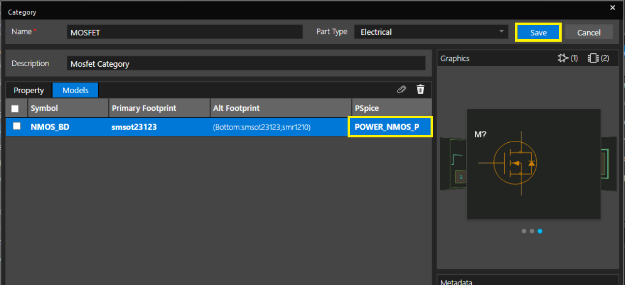
- Note that the PSpice model has been added in the created part category. Click Save.
- The MOSFET category has been created successfully.
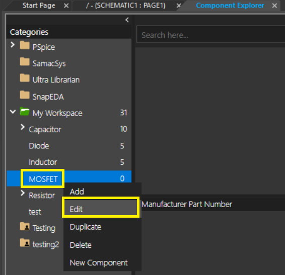
Note: If you want to edit details of the created category, right-click on the category and select Edit.
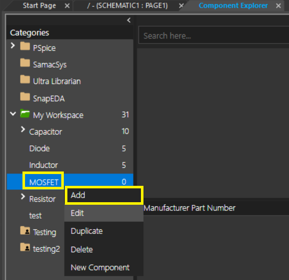
Follow these steps to create a subcategory for the created category:
- Right-click on the MOSFETcategory and select Add.
- This will add the subcategory under MOSFET as shown below.
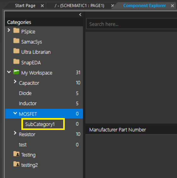
- You can rename the subcategory by right-clicking on it and selecting Edit.