12 - Reviewing and Analyzing Designs in OrCAD X Presto
Analyzing Design in OrCAD X Presto 3D Environment
OrCAD X Presto includes Allegro X 3D Canvas, a powerful graphical engine designed to display 3D models of design objects. This 3D viewer allows you to review designs before creating manufacturing outputs, exchange data with other applications, and customize the visibility of design objects and layers. Additionally, it supports various functions, such as measuring distances between objects and performing flex operations.
Overview of the OrCAD X Presto 3D Environment
The OrCAD X Presto 3D environment enables you to view and edit footprints and layouts, and includes the following 3D capabilities:
Component Shape Visibility
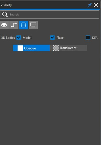
With the Components tab of the Visibility panel, you can control the visibility state of the Place Bound or DFA Bound extrusions and mapped 3D models, and toggle between the Opaque and Translucent states for enabled representations, as follows:
Visibility Panel Components Tab
Footprint Boundaries
To accurately display the positive material of layers such as solder mask and dielectric, the 3D view requires an overall design boundary. When used for board-level visualization the overall design boundary is taken from the design. However, footprints lack an explicit design boundary.
The overall 2D box extent for the footprint objects, plus an additional apron, will be computed dynamically and used as the footprint design boundary.
As objects (pins, shapes, and so on) are added, removed, or modified, the boundary is updated to use the minimum required area to include all relevant 3D footprint objects. For example, if a silkscreen shape is added outside the current boundary then the boundary will be enlarged just enough to include it.
In the following example, the computed 2D extent is outlined in red, while the overall 2D extent (computed + apron) is outlined in yellow.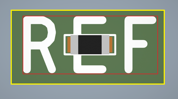
3D Models
You can control the mapped 3D model for the footprint through the top-level 3D Model field in the property panel. When there is no existing 3D model mapped to the footprint:
- The text portion of the “3D Model” field will appear empty and you can use the plus (+) icon button to import a new 3D model for the footprint, as follows:
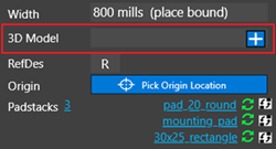
- Click the plus icon to open a file dialog and browse to the desired 3D model file.
- Choose a model file, and it will be imported to the drawing at the drawing origin location, and the 3D view will update to display the model.
- Any errors or warnings during this procedure will appear as messages in the session log.
When mapping an existing 3D model to the footprint, the text portion of the 3D Model field displays the name of the associated model, and you will see two icon buttons, as follows.
- Use the “refresh” icon to browse to a 3D model file, and import the chosen model while keeping the existing 3D model mapping transform.
- Use the minus (-) icon to remove the 3D model from the footprint and any mapping transform information for the model.
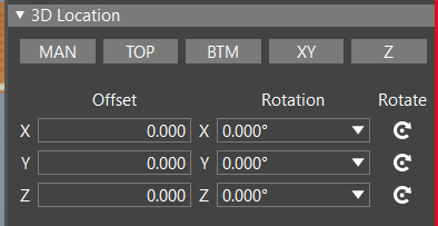
To edit the 3D model mapping, use the 3D Location top-level accordion group in the property panel when the footprint has an associated 3D model:
- The mapping transform tools group is visible when 3D is the active view and the footprint has an associated 3D model. Otherwise, you will not see the 3D Location.
- No active selection is required to perform the mapping operations (for example, alignment, rotation, and so on).
- Other editing operations (text fields, rotate buttons, alignment, and so on) will be similar to those for board-level mechanical model mapping with 3DX.
Generating 3D Exports in OrCAD X Presto
For ECAD and MCAD analysis, it is often required to export 3D data of board designs. OrCAD X , Presto, provides option to export 3D design data in multiple output formats. The 3D design data can also be exported for rigid-flex designs when the design is folded or bent. The export option is fully customizable and exports the data depending on the visibility of the straight or foldable state of the design. To generate 3D exports in OrCAD X Presto, do the following:
- Choose File – 3D Export.
A docked 3DExport panel opens in a separate tab at the location of the Properties panel. - Modify the options for 2D and 3D display in the Options and 3D Display tab. The 3D Display
tab is functional only when the display mode is set to 3D in the Visibility panel.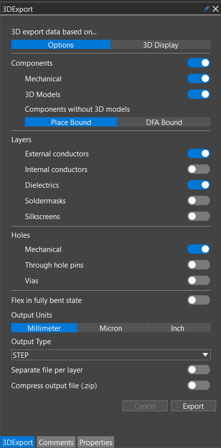
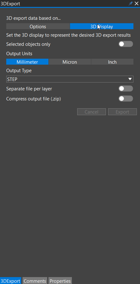
- Enable Selected objects only to output only the objects selected in the design canvas.
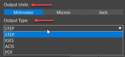
- Select the output units and the output file format.
- Click Export.
A file browser opens. - Specify the name and path of the output file and click the Save button. The output file contains the 3D representation of the design based on the visibility settings in the specified directory.
You cannot modify the display while the 3D export is in process.
Reviewing Designs Using Comments and Markups in OrCAD X Presto
Adding comments using markups is a simple design review feature that streamlines the PCB design review process across different design teams or domains. The design review solution, integrated within the layout editor, eases the collaboration with assembly and fabrication houses, manages review data efficiently, and keeps it up to date.
This design review functionality works in a single-user mode. You can mark any area in the design canvas using rectangular or arrow markups and add text comments in the Comments panel. Each comment is saved with a unique ID. You can add text comments to individual layers with or without markup. A comment may have more than one markup associated with it.
To view all the markups, zoom in to fit the design in the canvas. You can navigate comments in the Comments panel or by selecting the markups in the design canvas. The layout editor retains the layer visibility and zoom info when navigating comments or markups.
The markup data is saved with the design database and transferred to other users when the design is shared for task assignments or exchange of information. You can remove all the markup data from a design by archiving it in a file before sharing it with external reviewers. Using this design review functionality, multiple users can easily collaborate and work on design iterations.
Operations on the design objects are not permitted while working with markups and comments. To work on design objects, click the select icon from the floating toolbar. You can switch between markup and design editing modes by selecting relevant icons.
The markup functionality is not supported with non-openGL mode, 3D viewing mode, or collaborative design mode (team design and cloud).
- Adding Comments and Markups in OrCAD X Presto
- Editing Comments and Markups in OrCAD X Presto
- Viewing and Navigating Comments and Markups in OrCAD X Presto
- Archiving Comments and Markups in OrCAD X Presto
Adding Comments and Markups in OrCAD X Presto
Adding comments when reviewing designs is available only in the single-user mode. Any number of comments can be added to a design. Comments can also be added with or without markups. Furthermore, multiple markups can be associated with a single comment.
To add comments, do the following:
- Choose the Markup menu or click the Markup icon in the toolbar. An empty Comment panel opens. If the design already has comments, the panel displays pre-populated review comments from previous sessions.
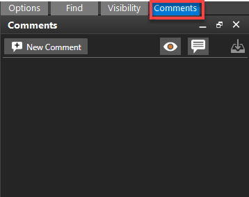
When the markup command is active, no operations on the design objects can be performed. - Click the New Comment button. A new comment card opens at the top. Existing comments are pushed below to it.
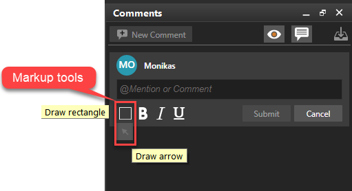
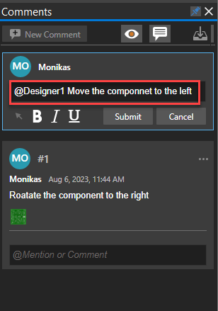
The comment card displays the user name, user avatar, text field, markup tools, text formatting buttons, and options to save or discard a comment. A comment text can be formatted using the rich text features (bold, italic, underline). A markup is a graphical annotation in the design
canvas highlighting the areas where comments are added. The user ID is created from the first two letters of the user name. - Select the markup tool in the comment card. Draw a rectangle to mark a rectangular-shaped area or an arrow to point to an object in the design canvas. Enter the comment in the text field, and press Submit.
A markup is added in yellow as a rectangle to the design canvas. The hash character denotes the comment ID during the markup placement.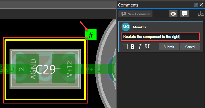
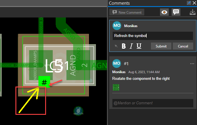
Once the comment is submitted, a unique ID is assigned to it. The markup data is attached to the board design database, enabling other users to view markup data without extra settings
when the marked-up design is opened. The markup data includes comment ID, a timestamp that displays the local time zone, and a snapshot of the design (.png) and is displayed in the Comments panel. It also includes layer visibility and zoom information of the design when the comment was added.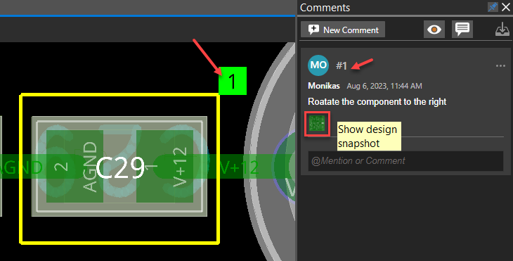
- Specify the user ID with a @ prefix to the comment text for assigning tasks to individual users. An assigned label is displayed in blue with that comment. Additionally, a blue bar gets added to the top edge of the comment with a task assigned to it, differentiating it from general comments.
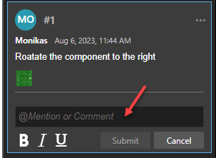
- Click the text field below a comment to add a reply.
By default, comments are shown in the collapsed state; only the first and the last responses are displayed. Clicking the top-level comment expands the whole thread.
Editing Comments and Markups in OrCAD X Presto
To modify review comments and markups, do the following:
- Choose the Markup menu or click the Markup icon in the toolbar.
- In the Comments panel, select a comment to modify.
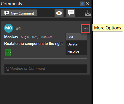
- Click the More Options icon to choose options to edit, delete, or resolve a comment.
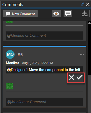
- Click Edit to modify the comment text. Select the appropriate icons below the text field to save or discard the modified text.
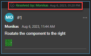
- Click Resolve to close an open comment. A reply can be added when marking it resolved, The resolved comment displays the status and the user name who resolved it. A comment, when resolved, removes its markup from the canvas.
- Click More Options in the resolved comment section and select Reopen. The comment is reopened for further work, and the markup is restored in the design canvas.
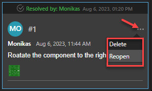
- Select Delete in the More Options list of the resolved comment.
The comment is deleted from the markup database and cannot be restored.
- Click Edit to modify the comment text. Select the appropriate icons below the text field to save or discard the modified text.
- Select the markup in the design canvas, right-click, and choose Change Markup Color. Click a different color in the color palette in the Assign Color dialog box.
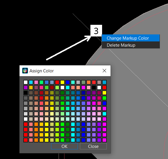
- Select the markup for the comments that have been resolved. Right-click and choose the
Delete Markup option.
The markup is deleted from the design canvas. The comments associated with the markup remain in the Comment panel until deleted manually.
Viewing and Navigating Comments and Markups in OrCAD X Presto
To view and navigate through the comments and markups in the layout editor, do the following:
- Open a design with existing comments and activate markups by clicking the Markup icon in the toolbar or selecting a comment in the Comments panel.
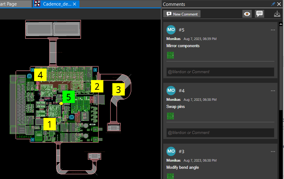
- Choose View – Zoom – Zoom Fit or click the Zoom Fit icon from the floating toolbar. Only the markup annotations are displayed in yellow.
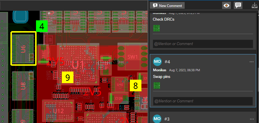
- Click to select a markup annotation in the design canvas. A markup annotation, when selected, turns green. The comment associated with that markup is also highlighted in the Comments panel.
- Hover the cursor over the markup ID.
The marked-up area gets highlighted.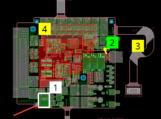
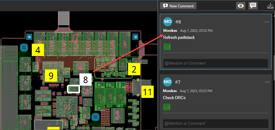
- Click to select a comment in the Comments panel.
The relevant comment and markup are expanded and highlighted in the Comments panel and design canvas. The markup is displayed the same layer visibility and zoom state of the design when the comment was added.
- Click anywhere in the blank space to deselect the comment.
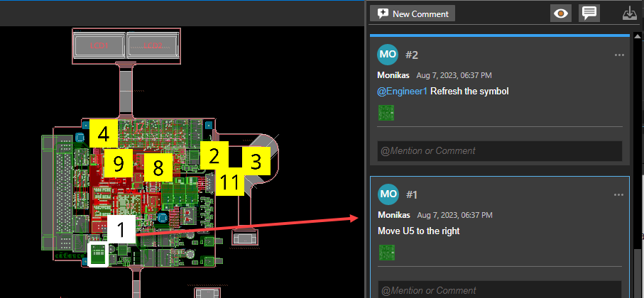
- Keep clicking comments to navigate them in the design. The other way to navigate comments is to select markup annotations in the design canvas.
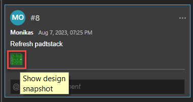
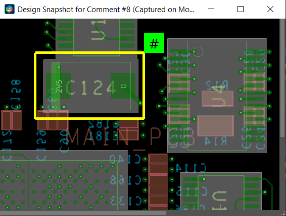
- Click the Show Design Snapshot icon in the comment card to view the canvas snapshot in a separate window that displays the state of design with the markup area when the comment was added.
- Click the Toggle markup visibility icon in the Comments panel to hide markups in the design canvas. It is useful when making design edits.
All the markups become invisible in the design canvas. The comments remain available in the
Comments panel.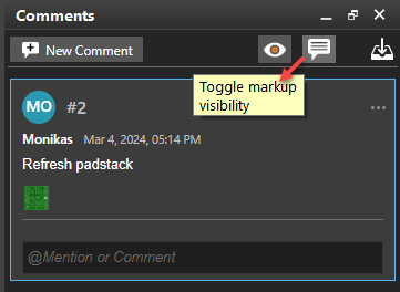
- In the Visibility panel, turn on the visibility of a specific layer and click the Toggle layer visibility
icon in the Comment panel.
The layer visibility of individual comments is turned off and not used when displaying markups and comments. When selected, a comment zooms to the markup location using the layer visibility as specified in the Visibility panel.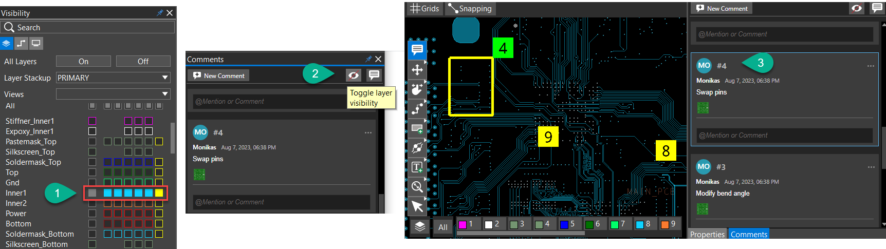
Similarly, with this option enabled, selecting markup annotations in the design canvas highlights the relevant comments in the Comments panel while retaining the layer visibility. - Click zoom icons from the floating toolbar to view the markups in the design canvas.
The markup objects expand or contract with the zoom level. However, the size of the markup annotation remains static and does not change with the zoom changes.
Archiving Comments and Markups in OrCAD X Presto
A design with internal markup and comments may reveal unintentional information when shared with external reviewers or subcontractors. To prevent this, you can extract all review and markup data to a file and remove them from the design. Perform the following steps to remove all the review comments and markups from a design and archive them in an external file:
- Choose the Markup menu or click the Markup icon in the toolbar.
- Click the Archive and remove comments icon in the Comments panel.
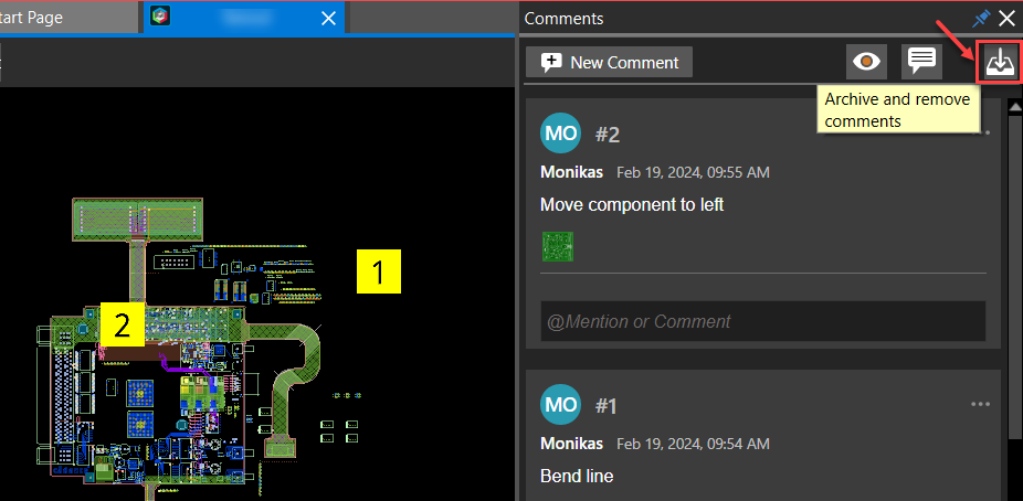
All the markups and review comments are immediately removed from the design, and the icon turns gray. The markup information is exported to a markup_archive_<design_ name>_<date> folder created in the current design directory. This folder includes an ASCII file (.json) containing all markup comments and snapshot images for each comment.
Generating Reports in OrCAD X Presto
OrCAD X Presto has a reporting mechanism that enables you to browse or search through a list of reports and choose specific items on which to focus so you can flag or resolve any issues.
For example, you might want to run reports on shape islands or unassigned shapes; missing teardrops or tapers; and dangling traces, vias and antenna.
You can run and access reports as follows:
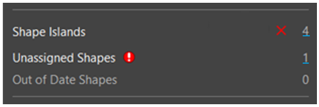
- By clicking on a blue hyperlink from a design-level property panel or object level property (Shape Islands, for example):
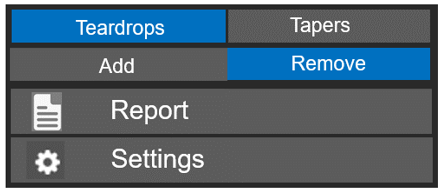
- From an active command (Teardrops, for example):
- From the top-level Reports menu:
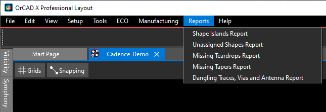
Once you have run a report, it appears in a Reports panel, as seen at the bottom of the following Missing Teardops example: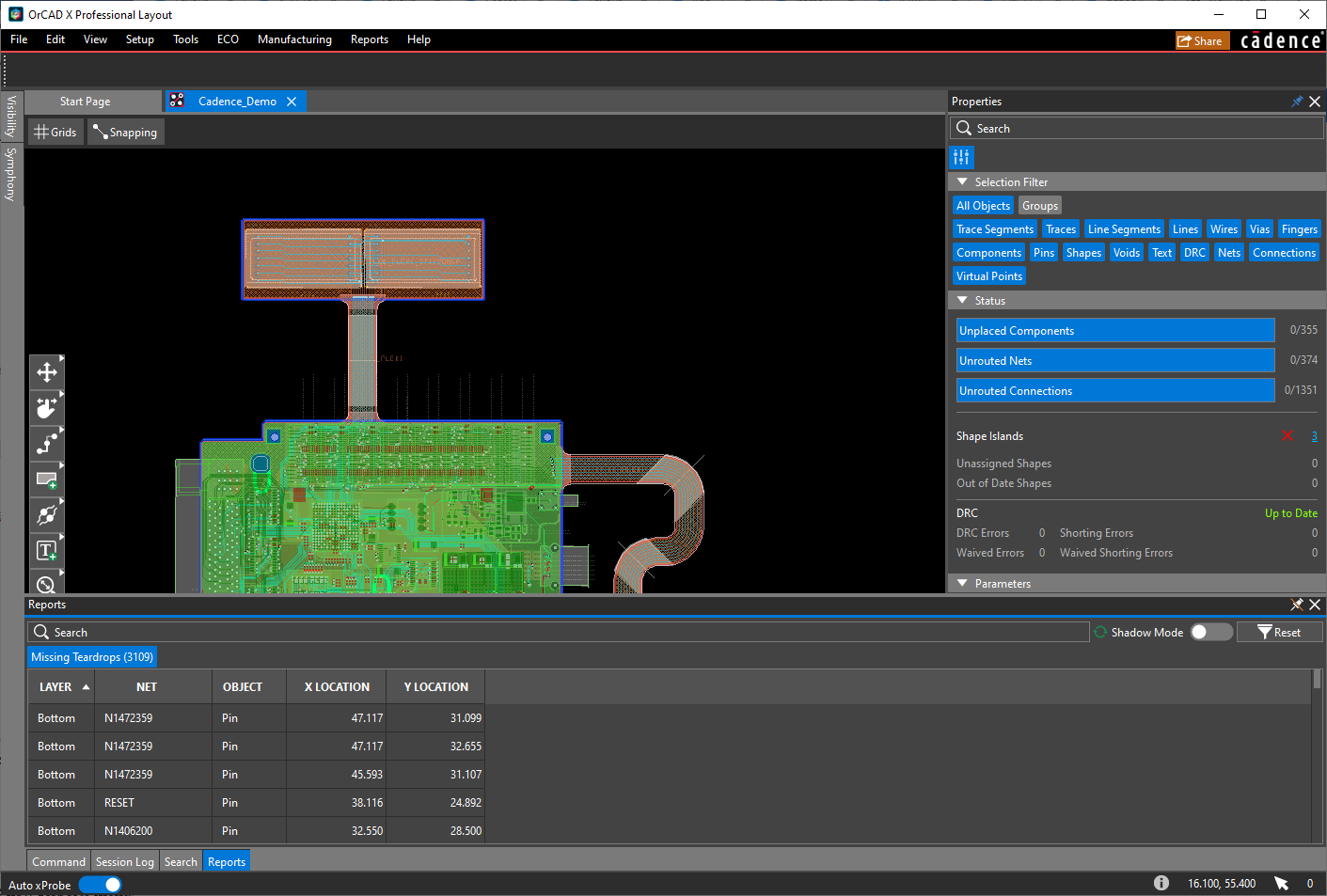
You can then click through the tabs at the bottom of the Reports panel.
![]()
To Search, for example: 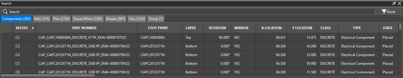
and find specific data. For example, CADENCE_LOGO:
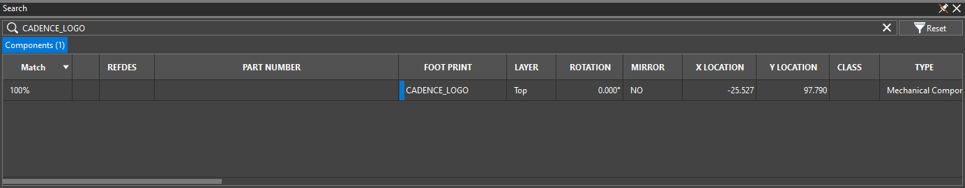
You can then either double-click or right-click on any piece of of data to, for example, Zoom, Edit, or Select on Canvas.
Reports generated are a snapshot of the database state at the time the report data is retrieved. This data is static, but you can use the refresh button on the panel or rerun the report for updated data.
Dangling Traces, Vias and Antenna Report
The dangling traces, vias and antenna report contains two separate tabs—one for dangling traces,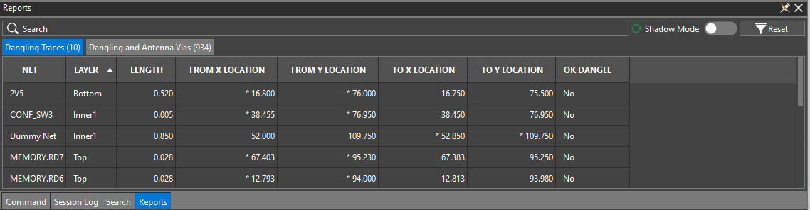
and one for dangling and antenna vias.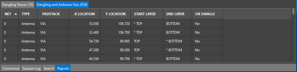
All columns in the both tabs of the dangling traces, vias and antenna report are read-only and simply informational, except for OK Dangle, which enables you to set or reset the OK_DANGLE attribute for the related trace or via.
Note that report results are not dynamic, so you must refresh or rerun the report to update results.
Missing Tapers Report
A typical missing tapers report might look as follows:
typical missing tapers report might look as follows:
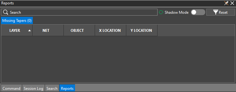
All fields in the missing tapers report are read-only and simply informational.
Missing Teardrops Report
A typical missing teardrops report might look as follows:
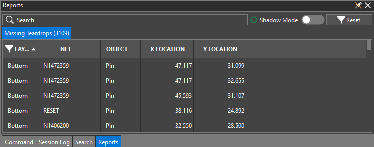
All fields in the missing teardrops report are read-only and simply informational.
Shape Islands Report
A typical shape islands report might look as follows:
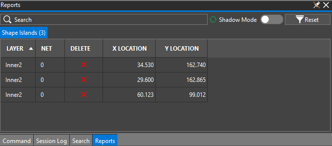
All columns in the shape islands report are read-only and simply informational, except for Delete. You can click on the X icon in any row of the Delete column to disable that row (as the second row, following).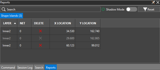
Unassigned Shapes Report
A typical unassigned shapes report might look as follows: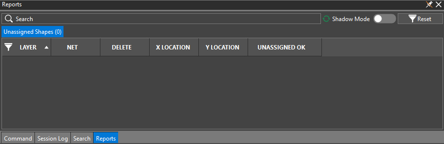
The Layer, X Location, and Y Location columns in the unassigned shapes report are read-only and simply informational.
The following columns, however, are editable:
- The Net column enables you to choose the net you want from the drop-down list.
- The Delete column enables you to click on the X icon in any row to disable that row and delete the unassigned shape.
- The Unassigned OK column enables you to indicate whether is is okay (Yes) or not (No) to leave the shape net unassigned.
View the next document: 13 - Integrated Design Analysis
If you have any questions or comments about the OrCAD X platform, click on the link below.
Contact Us