11 - Documenting the PCB with Live Doc in OrCAD X Presto
A wide variety of documents are used to capture the requirements for fabrication assembly and testing of a PCB, including fabrication drawing, dimensioning, drill data, stack-up data, fabrication notes, assembly drawing, BOM drawing, artwork, and so on.
These documents follow multiple industry standards but are prone to human error during creation and interpretation.
What is Live Doc? Launching Live Doc Live Doc User Interface Live Doc Preferences Using Live Doc Templates Live Doc Workflow Adding Page in Live Doc Defining Page Title BlockPCB Views in Live Doc Placing PCB Views in Live Doc Viewing and Sharing PCB Views in Live Doc Defining Dimensions in Live Doc Defining Annotations in Live Doc Managing Live Doc
What is Live Doc?
Live Doc is a PCB documentation-authoring tool, integrated with OrCAD X Presto, that automates the documentation creation process to produce complex PCB documentation in a fraction of the time it takes using the traditional methods. As a result, it reduces the effort of manually creating and maintaining multiple documents and eliminates the scope of human error.
Utilizing the board design data, Live Doc creates linked PCB views, drawing details, document notes, drill charts, and other crucial documentation details. The result is documentation that more accurately articulates instructions for the successful fabrication, assembly, and inspection of PCBs.
The Live Doc documentation environment enables designers to convey manufacturing, assembly, and testing requirements to fabrication and assembly partners quickly, simply, and automatically. The unified environment ensures that the information is up-to-date, accurate, and ready to share.
Live Doc is a Windows-based application.
Key Features of Live Doc
Live Doc offers all drafting and dimensioning functionalities to automate the creation of fabrication drawings, assembly drawings, and manufacturing files. Some of the key features of Live Doc include:
- Derives the data from the active board design file to create drawings. Design changes made in OrCAD X Presto are automatically propagated to all the affected drawing elements, reducing time spent on updating the documentation due to the design changes. Live Doc reads and writes data to and from the primary board file and saves it with the board database.
- Provides tight integration with OrCAD X Presto that enables simple click-through passing of design data to expedite the drawing creation process.
- It is an interactive documentation editor driven by Place, Properties, and Visibility panels to create manufacturing drawings.
- Displays PCB views from a default template with predefined grid settings. The PCB views are scaled-down replicas of the same information in the primary board file.
- Automatically generates component assembly views, drill pattern views, details, and charts. It also generates drawings from customized templates. These templates are created based on the requirements, which can also be exported to other designs. Any changes to the board file are dynamically propagated to the Live Doc views, ensuring consistency.
- A single file can be exported in a PDF format for sharing and reviewing using a web browser.
- Quickly document PCB requirements with dimensioning, standard fabrication, and assembly notes.
Launching Live Doc
Start Live Doc as follows:
- Open OrCAD X Presto using one of the following methods:
- Choose Start – Cadence PCB 2023 – OrCAD X Presto 2023 on Windows. Alternatively, type orcadx & at the Windows command prompt and press Enter. The Cadence Product Choices dialog box is displayed.
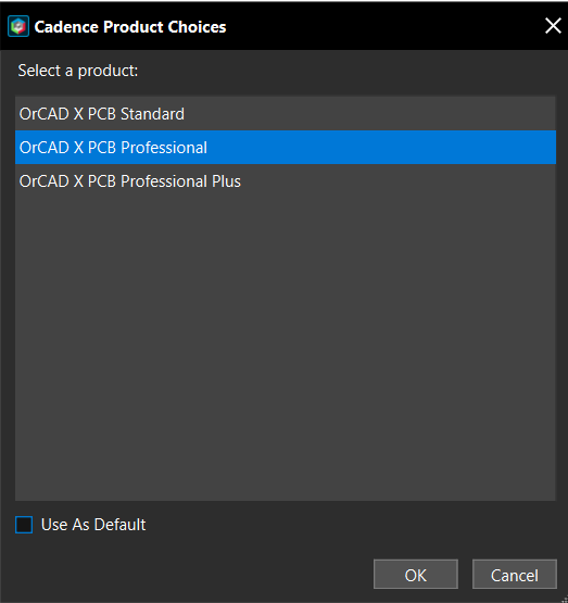
- Choose a product license and click OK.
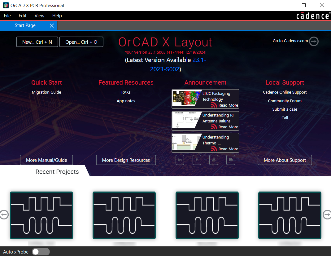
OrCAD X Layout is launched, and the Start Page is displayed.
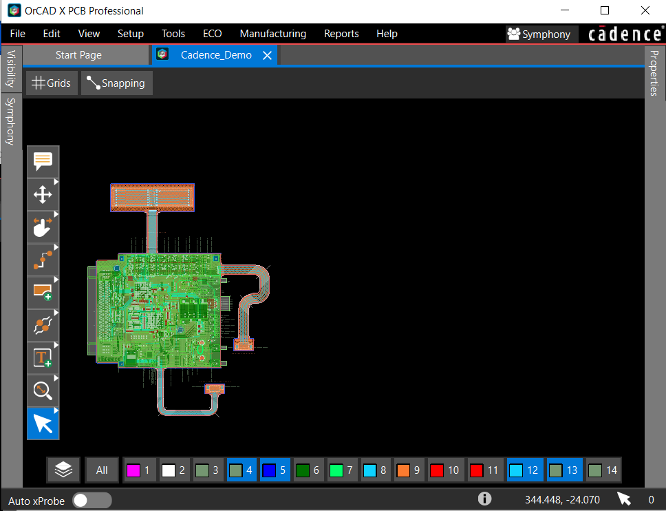
- Choose File – Open and choose a board design (.brd) file. The selected board design is loaded in a new tab.
- Choose Manufacturing – Live Doc – Create New From Template.
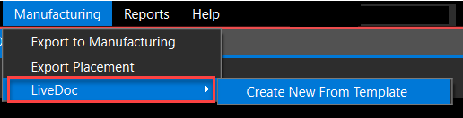
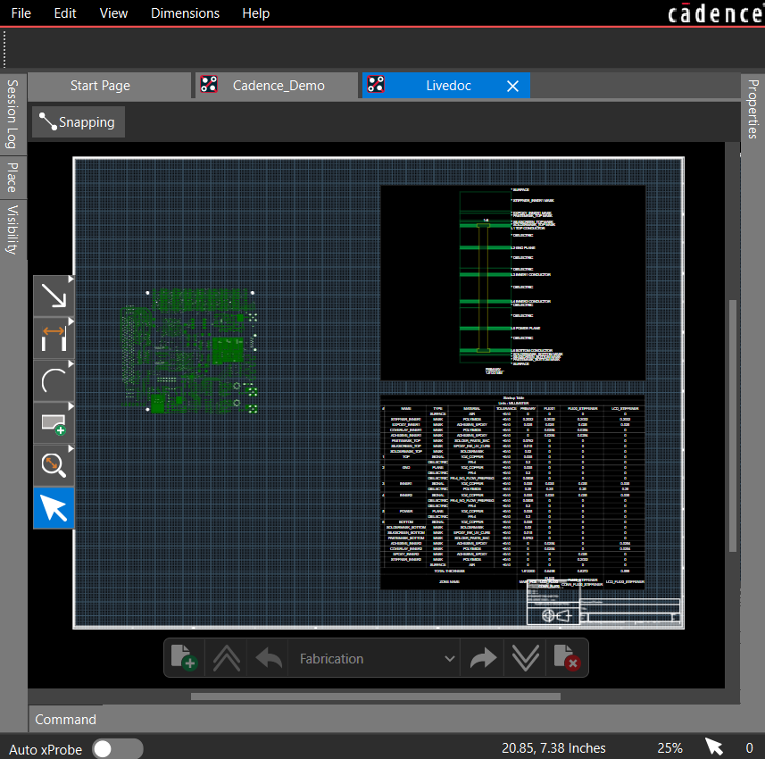
A bar shows while Live Doc is uploading. After the upload, the Live Doc view of the current board design is opened in a separate tab. Fabrication and assembly pages are loaded automatically for an active design.
When you close the Live Doc tab, the Live Doc data is saved with the design database. It is accessible when you reopen the design.
Live Doc User Interface
The user interface of Live Doc is similar to the main window of OrCAD X Presto and displays its panels, menus, and toolbars.
Live Doc Canvas
The Live Doc canvas is the center panel of the main window where PCB views are placed. When you open a new page in Live Doc, a default page border is already placed that can be replaced with a different page border available in the design library. The page border size determines the extent of the Live Doc canvas. Live Doc displays only one page at a time.
You can pan a Live Doc canvas using a mouse or arrow keys on the keyboard. Press and hold the middle mouse button and slide the mouse to the left, right, up, and down. You can also use the arrow keys on a keyboard to pan. The panning stops when you move the mouse outside of the Live Doc canvas.
Snapping controls are also accessible from the Live Doc canvas.
Snapping controls are applied only when adding or modifying dimensions to Live Doc.
Panels
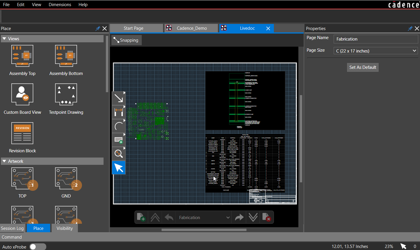
The Place panel contains PCB views for artwork, fabrication drawings, stack-up charts, and tables required for fabrication and assembly drawings. It displays the most common drawings and
manufacturing outputs to create production documents. You can choose one of these PCB views and place it anywhere in the Live Doc canvas.
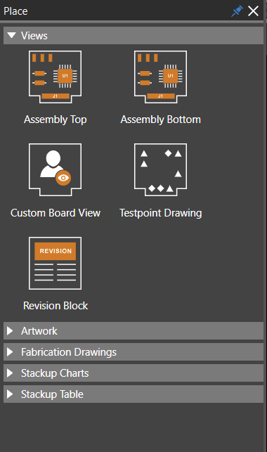
For example, placing an Artwork view populates the view based on the artwork generated from the board design.
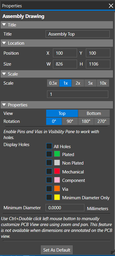
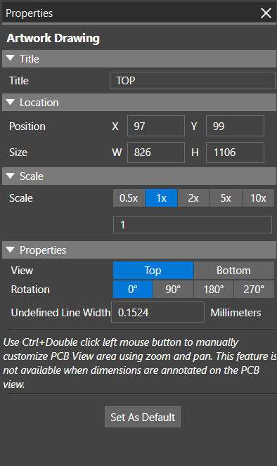
The Properties panel displays the properties of the selected object. In this panel, you can also edit information about the object that you have selected. When nothing is selected, the page border settings are displayed.
You can use the Set As Default option to save the current settings as default. Enabling this option eliminates the need to modify the properties of the same object when added to the Live Doc canvas. When set as default, the modified property settings are saved with the Live Doc data and available across sessions for the same design.
To reuse the property settings in other designs, create a new Live Doc template using the File – Save As Template command. Use this template to create Live Doc for new designs.
The Properties panel displays the properties of an object or PCB view selected in the Live Doc canvas as follows:
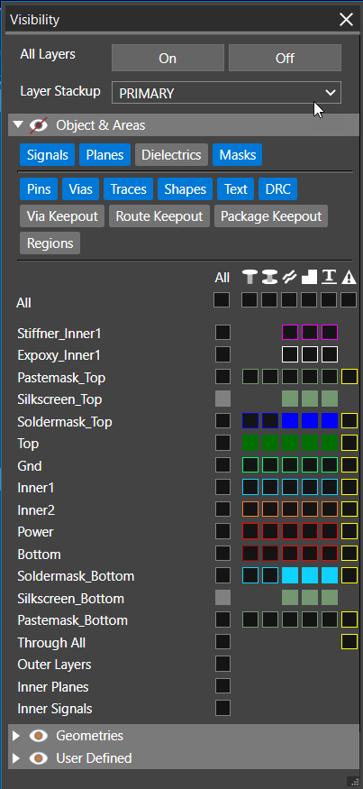
The Visibility panel controls the visibility of objects inside a selected PCB view. Selecting a different PCB view changes the settings in the Visibility panel.
Toolbars
There are two floating toolbars in the main window:
- Command Toolbar
- Page Toolbar
Command Toolbar
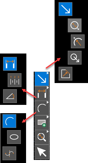
The command toolbar is vertically aligned and provides controls to add PCB views, dimensions, annotations, control zoom, and selection of objects. 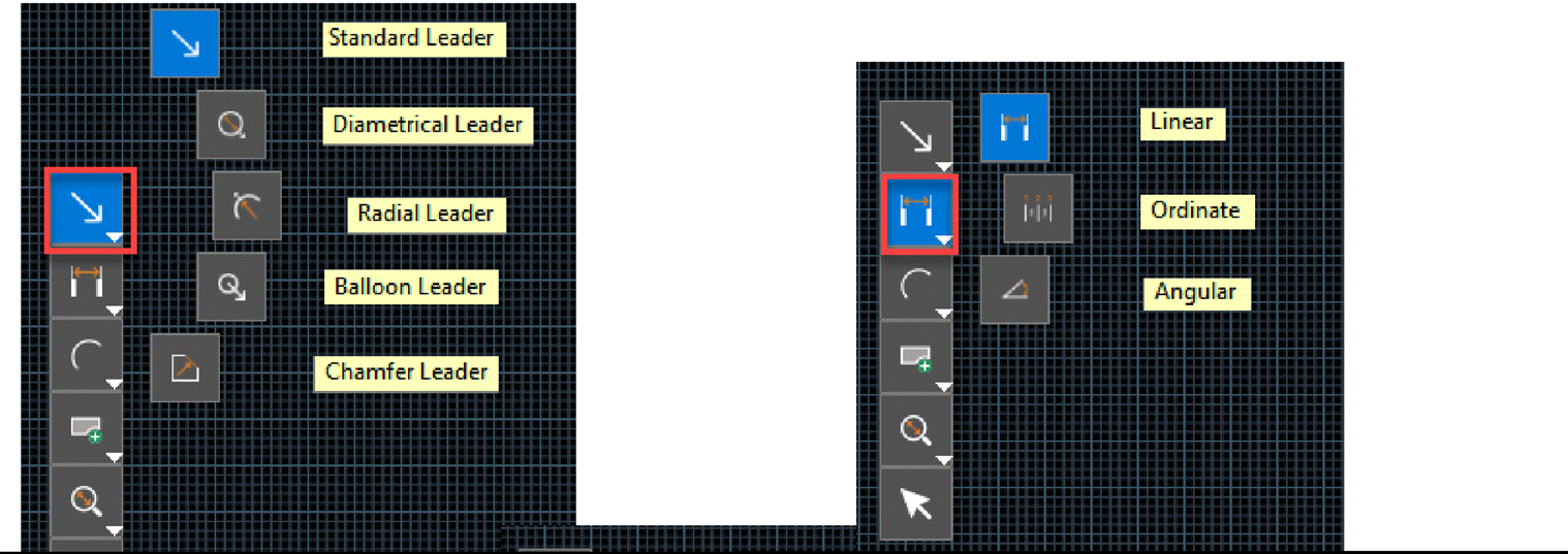
By default, the Select icon is enabled in the command toolbar. Remaining icons represent a set of command actions denoted by a small inverted triangle. You can right-click any of the icons to display its associated command icons. When you select an icon, it becomes the default icon in the toolbar.
Page Toolbar
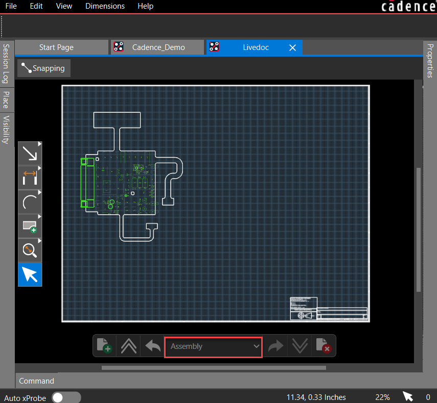
Live Doc supports multiple pages in a template that can be used to create various types of PCB documents. At the bottom of the design canvas, the page toolbar provides controls to include and exclude pages and navigation controls.
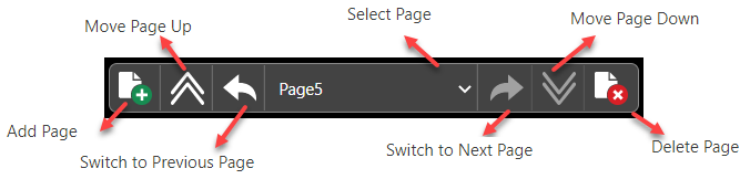
By default, Fabrication and Assembly pages are available in the template.
Page settings, such as name and size, can be modified in the Properties panel at any time during the documentation process.
Live Doc Preferences
The Live Doc application works with a predefined set of preferences specified in the Preferences dialog box. 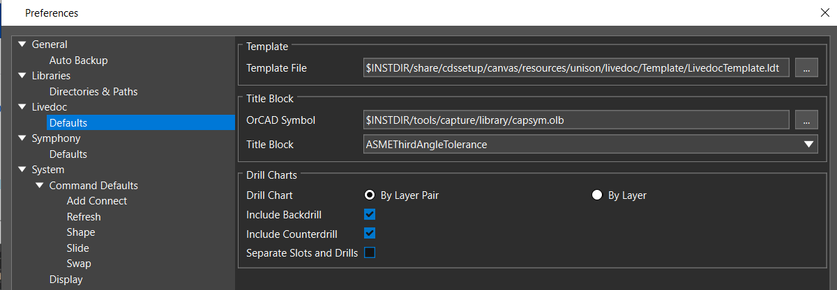
In the Preferences dialog box, you can modify the following:
- Template File: Specifies the path to the default template file (Live DocTemplate.ldt) from the following directory location of the install area:
<install_directory>/share/cdssetup/canvas/resources/unison/Live Doc/Template
You can also specify the path to any custom template file.
The new template file is used only for creating a new Live Doc. All the existing board designs containing Live Doc data remain unaffected.
- Title Block: Specifies the path to the OrCAD symbol library (.olb) and the name of the title block symbol used with the default page border. It contains various fields that identify the drawing and other details, such as company logo and address, title, drawing number, revision, sheet size, drawn by, checked by, approved by, with dates, sheet number, drawing scale, and so on.
- Drill Chart: Controls the options of the drill chart. A drill chart represents drill hole sizes and locations as a graphical symbol. The location of the symbol marks the location of the drill in the PCB, and the symbol maps to a drill chart that defines the hole size, tolerances, and plating status. You can create a drill chart by layer pair or layer, including backdrill, counterdrill, and separate slots and drills in the drill chart.
Using Live Doc Templates
A Live Doc template is a collection of PCB views of the board, tables, and charts placed across one or more pages for a design. A template includes page properties and custom PCB views used to create fabrication and assembly drawing from any board design. For example, if your company creates a three-page documentation of fabrication, assembly drawings, and manufacturing information, you can save this Live Doc as a template. Any new design using this template automatically generates the same set of PCB documents. The only additional task is to add design-specific data, such as dimensions and notes.
Creating Custom Templates
You can create custom templates by modifying the default template file Live DocTemplate.ldt
available in the install directory. To create a custom template, do the following:
- Open Live Doc using the default template.
- Add PCB views, charts, and tables to the Live Doc.
- Select individual PCB views and change their properties in the Properties panel.
- Save the modified template as a new template using File – Save As Template.
By specifying the template file path in the Preferences dialog box, the custom template can be used for new board designs.
Live Doc Workflow
The following sequence of tasks conveys the standard flow of tasks performed in Live Doc to create PCB documents when the design is ready for production:
- Create Live Doc using the default template
- Add pages to Live Doc
- Place default PCB views to Live Doc
- Create Custom PCB Views by modifying the default PCB view:
- Visibility of layers
- Properties of objects
- Supplement data for manufacturing and assembly by adding:
- Dimensions and leaders
- Graphical annotations and notes
- Save the customized Live Doc as a new template
- Export Live Doc as PDF for review
Adding Page in Live Doc
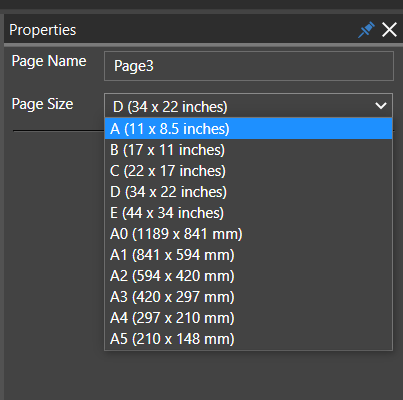
In Live Doc, you can select different page sizes for creating assembly and fabrication drawings in the
Properties panel. Do the following to change the default page size:
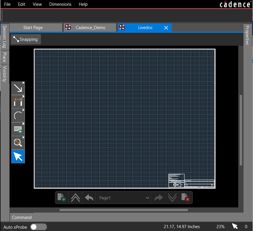
- Click the Add Page icon in the page toolbar.
The default page is added to the Live Doc canvas. The Properties panel displays its page attributes. - Expand the Page Size pull-down list in the Properties panel. The list displays default page sizes and their dimensions. The pages from A to E follow American Society of Mechanical Engineers (ASME) requirements and display size in inches. The pages from A0 to A5 conform to the International Organization for Standardization (ISO) and display size in millimeters.
- Choose another page size.
- Specify a name for the page.
The selected page is changed in the Live Doc canvas. All the measurements and the coordinates also start showing in the native unit of the page. - Optionally, click Set as Default. The selected page is used when adding new pages to the Live Doc.
Defining Page Title Block
A title block at the bottom right corner of a page indicates drawing details such as the title, document number, revision, and date when the drawing was created. To specify the title block properties, do the following:
- Open any page.
- Zoom into the bottom-right corner of the page and select the title block.
The title block specified in the Preferences dialog box is used. The page size, creation date and time, and page number are automatically populated in the title block. and the Properties panel displays its properties.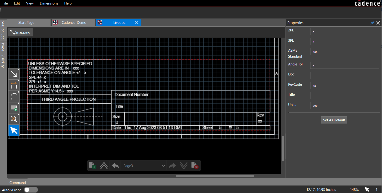
- Enter the title, document number, and revision in the Properties panel. The values are added to the title block.
- Alternatively, click Save a Default to use the same title block attributes for new pages.
- Open the Preferences dialog box and choose a different title block from the list.
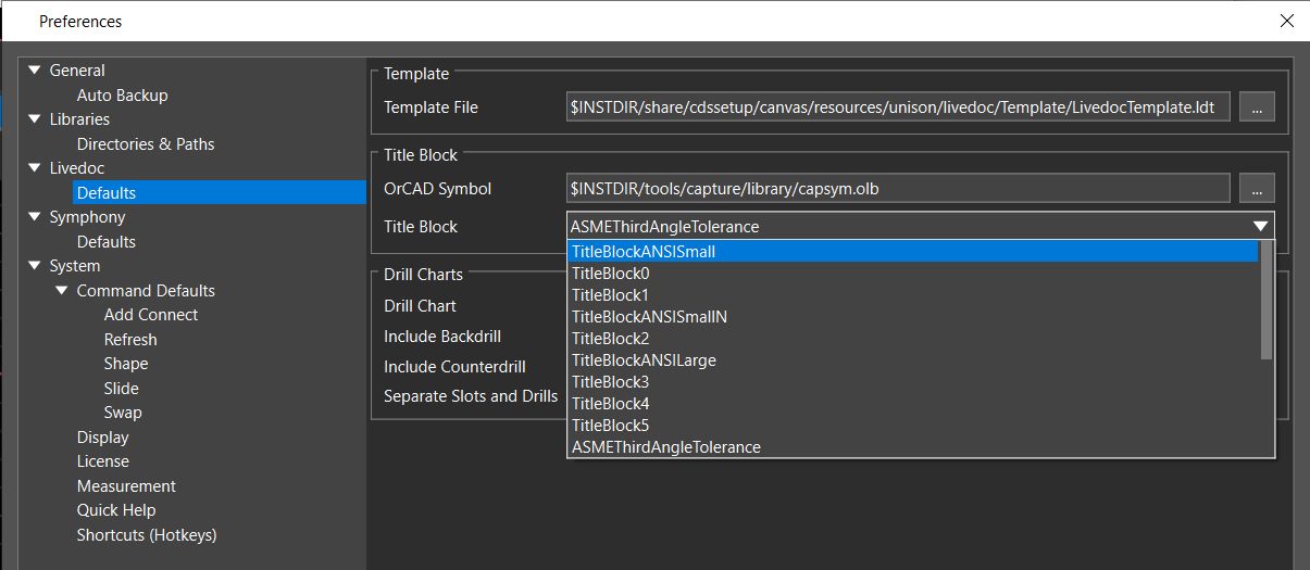
You see a different set of attributes in the Properties panel depending on which title block you select.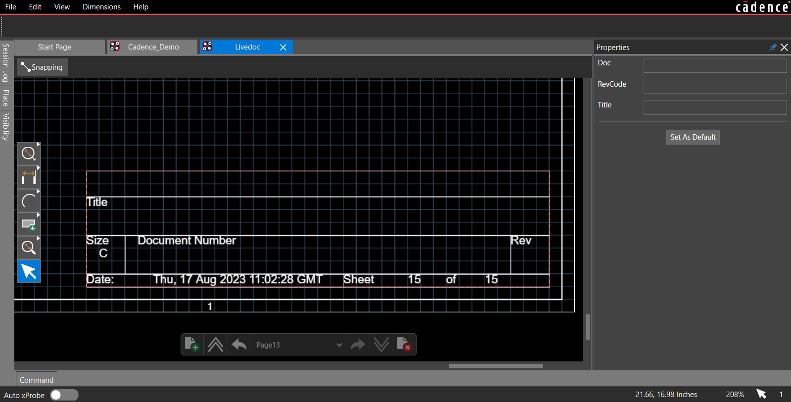
The selected title block is used only for new pages added to the Live Doc.
PCB Views in Live Doc
PCB views are different drawing types that include dimensional drawings, assembly drawings and instructions, Gerber files, fabrication documents, and so on. It takes a significant amount of time for complex PCB designs to create these documents to build, view, and archive the final product. Using Live Doc, you can quickly create the PCB drawings that drive PCB fabrication and assembly. Live Doc offers a default set of PCB drawings or PCB views that can be placed to document your PCB design. These predefined PCB views are auto-generated from the board design and can be placed and modified as required. You can create and place unlimited PCB views of the design. Each PCB view may have its own display settings and can be formatted independently of the board design.
Predefined PCB Views in Live Doc
Placing PCB Views in Live Doc
You can select PCB views in the Place panel and place them in the Live Doc canvas. Each PCB view can be scaled and formatted independently of the other. You can place as many PCB views as you want on each page. However, placing PCB views outside the extent of Live Doc canvas is not supported.
Extend the page border size or increase the view scaling in the Properties panel to fit more PCB views.
You can place specific PCB views of the board outline, assembly top/bottom views of the PCB, drill patterns and charts, stack-up tables, and so on. The default PCB views contain basic information about the design, such as placements of components and layer display. To further minimize rework, any customization for a PCB view is saved with the board design database and available when you reopen Live Doc.
Placing a PCB View in Live Doc Canvas
To place a PCB view, do the following:
- Select the icon for a PCB view in the Place panel.
The selected PCB view is highlighted in blue, and a white rectangle attached to the mouse cursor specifies the PCB view area on the canvas.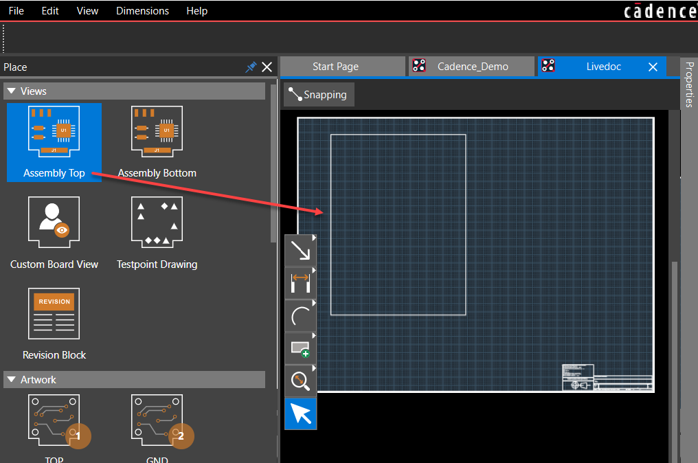
- Drag and drop the PCB view in the Live Doc canvas.
The selected view is placed on the Live Doc canvas inside a red rectangular area.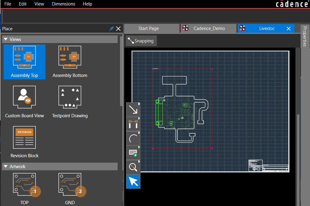
- Click to confirm the placement.
The selected PCB view is uploaded to the Live Doc canvas, and the Properties panel displays the basic information. The name of the PCB view is displayed at the top-left corner of the PCB view area, as shown in the following image: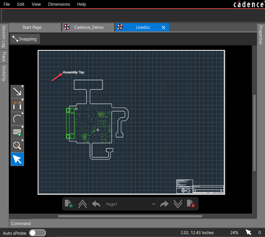
Placing Stackup Charts and Tables in Live Doc Canvas
To place stackup charts or tables in the Live Doc canvas, follow these steps:
- Click to select a stackup chart or table in the Place panel. The selected stackup chart or table is highlighted in blue.
- In the Live Doc canvas, draw a rectangle to place the selected stackup chart or table.
The selected stackup chart or table is uploaded to the Live Doc canvas inside a dashed-red border defining the size of the rectangle drawn.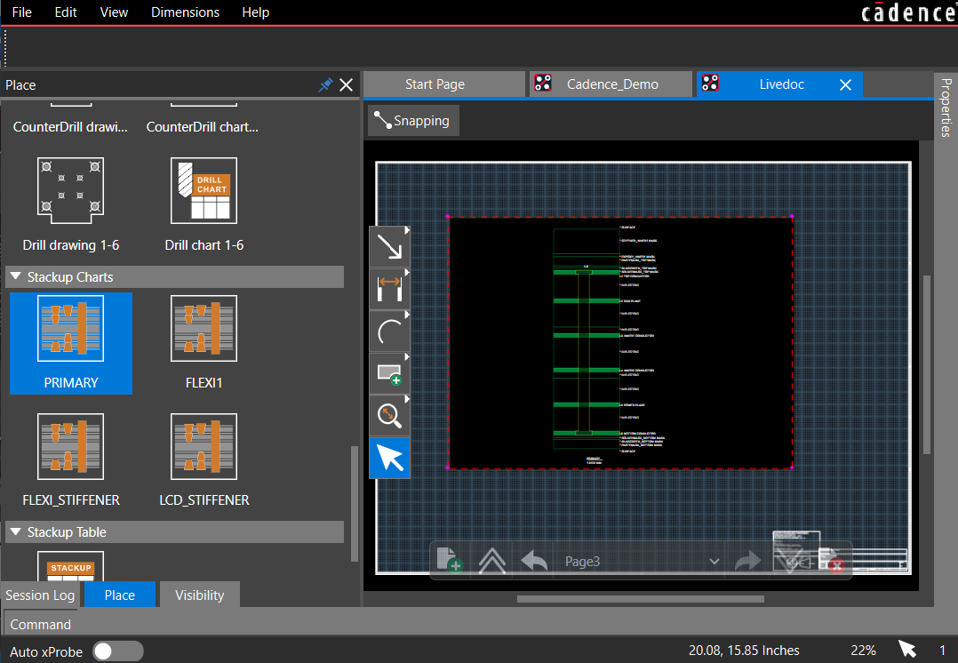
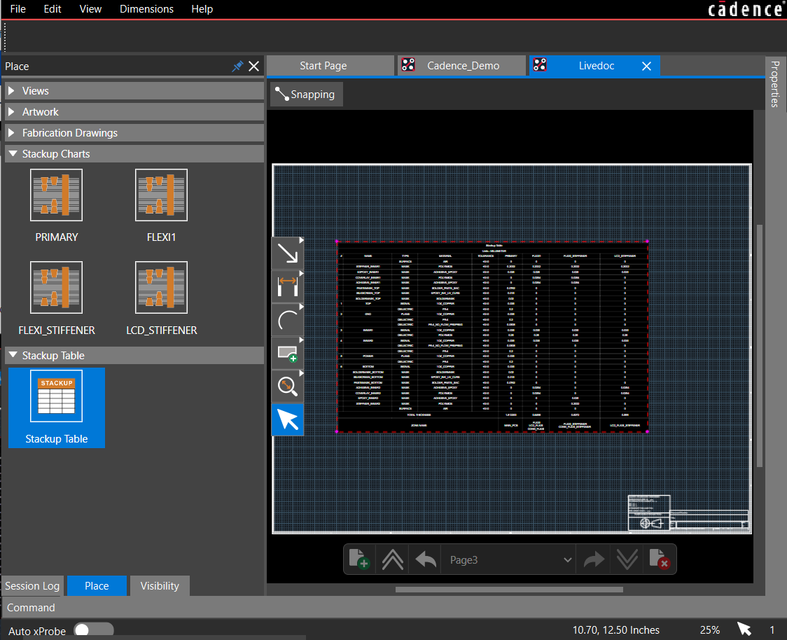
- Click on the design canvas to complete the placement.
The selected stackup chart or table is uploaded to the Live Doc canvas inside a red border defining the size of the rectangle drawn.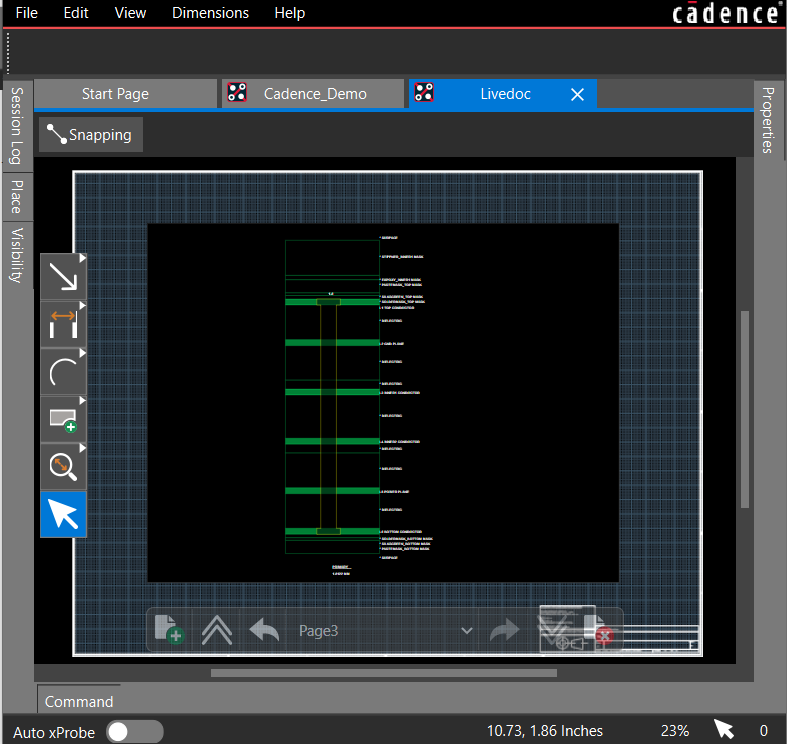
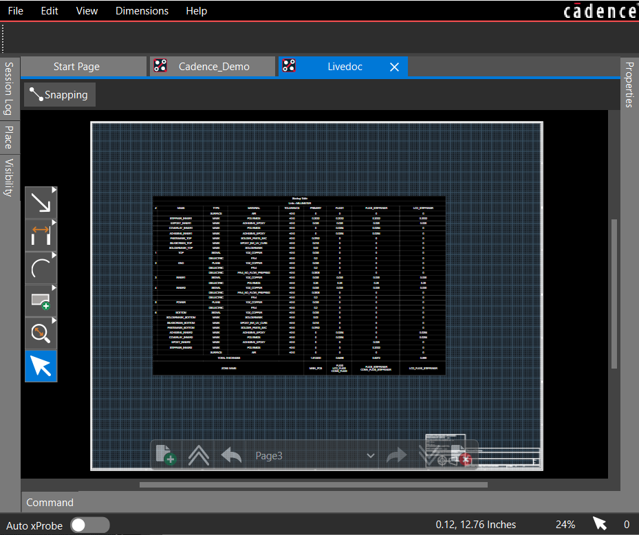
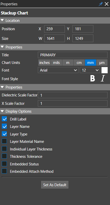
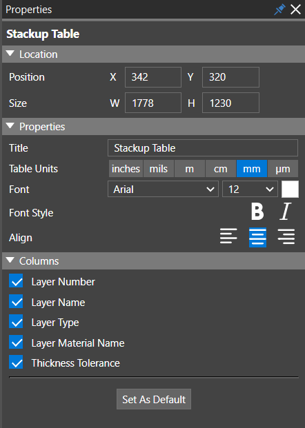
- Select the chart or table in the Live Doc canvas. The Properties panel displays the location, text attributes, and display options for the placed chart or table.
- Modify the chart or table properties in the Properties panel. Unselecting checkboxes under the Display Options or Columns section turns off the text associated with these settings in the chart or table.
Placing Drill Charts in Live Doc Canvas
To place drill charts in the Live Doc canvas, follow these steps
- Click to select a drill chart from the Fabrication Drawings section in the Place panel.
The selected drill chart highlights in blue. - Draw a rectangle to place the selected drill chart in the Live Doc canvas.
The selected drill chart is uploaded to the Live Doc canvas inside a dashed-red border defining the size of the rectangle drawn. - Click on the design canvas to complete the placement.
The selected drill chart is uploaded to the Live Doc canvas inside a red border defining the size of the rectangle drawn. The Properties panel displays the location, units, scaling methods, show or hide columns, and display options of the drill chart.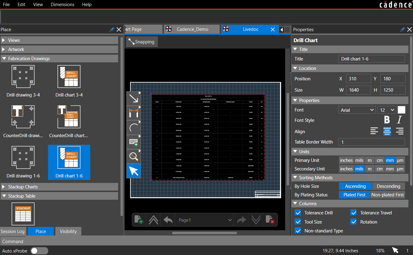
- Modify the drill chart properties in the Properties panel.
Unselecting checkboxes under the Display Options or Columns section turns off the text associated with these settings in the drill chart.
Viewing and Sharing PCB Views in Live Doc
When you select a PCB view in the Live Doc canvas by clicking anywhere inside the PCB view area, a red dashed-border rectangle highlights its boundary, and the Properties panel displays its properties. You can now control the display of objects and layers inside the PCB view.
Changing Display of PCB Views
You can resize a PCB view and also zoom in and out or pan to a specific location inside the view.
To zoom and pan inside a PCB view, follow these steps:
- Hold the Ctrl key and double-click anywhere inside the PCB view area. The cursor changes to a hand pointer.
- Use the left mouse button to pan the PCB view in the specified direction.
- Use mouse wheel in the forward and backward directions to enlarge or reduce the view.
Customizing PCB Views
Any PCB view of the design can be customized by modifying the visibility of the layers in that view. To modify the visibility of layers in a view, follow these steps:
- Open the Visibility panel after placing a PCB view in the Live Doc canvas. When nothing is selected, the panel is inactive.
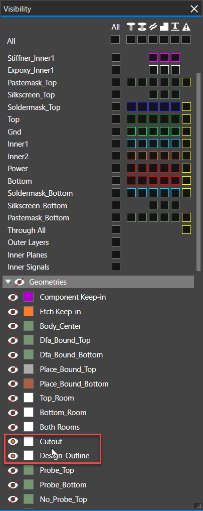
- To change the visibility of any layer, select the PCB view from the Live Doc canvas and dock the panel to the Live Doc window. The visibility of all the layers is set to off. Only the valid subclasses based on the selected PCB view are enabled in the Visibility panel under the Geometries and User Defined sections of Visibility panel.
For example, the following images illustrate the states of the Visibility panel of the Assembly Top view before and after it is selected in the Live Doc canvas.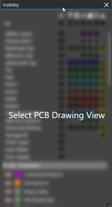
- In the Visibility panel, enable objects on any layer and modify the visibility of the relevant subclasses.
For example, the following image illustrates a custom PCB view Assembly Top Pin created from the Assembly Top view with pins enabled for the TOP layer.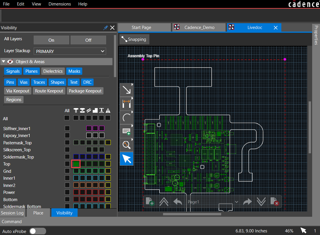
Exporting Live Doc Data to PDF
After placing all the default and custom PCB views, you can export Live Doc to a smart PDF format.
- Choose File – Export PDF to generate PDF output.
This multi-page single PDF file can be opened in a web browser and shared for review and analysis with manufacturing and assembly teams.
Defining Dimensions in Live Doc
You can add dimensions and leaders to objects in a PCB view to indicate the lengths, sizes, and angles of the object outline or the distance between the selected objects. Choose a dimension from the Dimensions menu or the command toolbar.
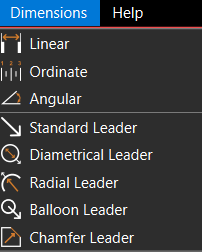
You can add linear, ordinate, and leader dimensions.
Adding Linear Dimensions
You can add linear dimensions to object outlines or between two points. To add linear dimensions, follow these steps:
- Add a new page in the Live Doc canvas using the page toolbar.
- Click to select a PCB view from the Place panel and add it to the Live Doc canvas.
- To zoom into a location where you want to add dimension, press and hold the Ctrl key and move the mouse wheel forward.
- Choose Dimensions – Linear or select the Linear dimension icon
 from the command toolbar.
 - Select the first point.
A white dot is displayed as a guideline, and the dimension is attached to the cursor. - Select the second point.
- Move the cursor to pick a location and click to place the linear dimension.
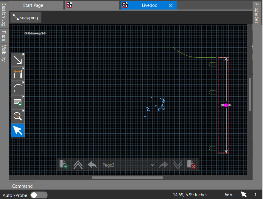
You can edit dimensioning parameters in the Properties panel. To modify a linear dimension, do the following:
- Choose the Select icon from the command toolbar and click the linear dimension in the Live Doc canvas.
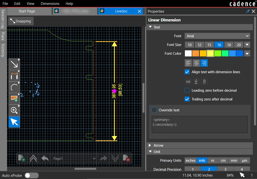
The Properties panel displays its properties in blue. A pink dot highlights the dimension value in the canvas.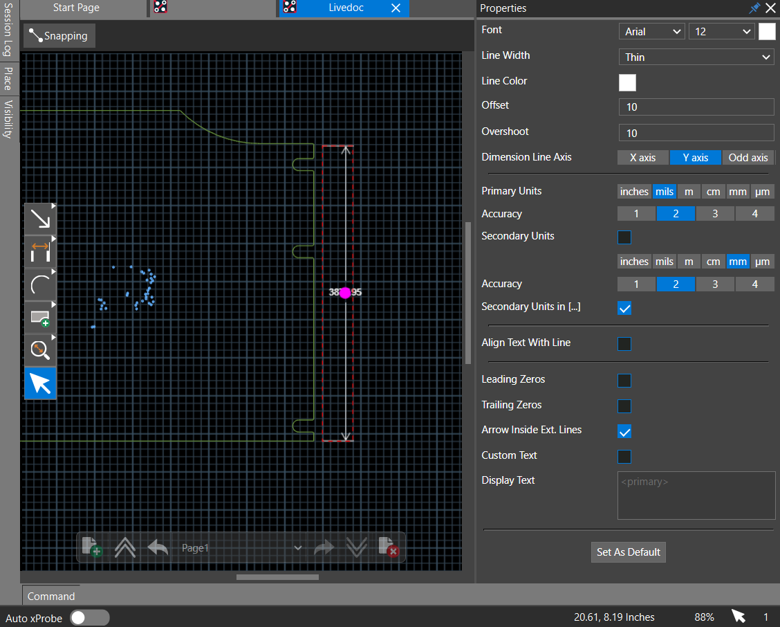
- In the Properties panel, change the following:
- In the Text pane:
- Set the Font Size to 16 and Font Color to yellow in the Text pane.
The font size of the dimension value increases and is displayed in yellow. - Select the Align text with dimension lines checkbox to align the dimension value with the line.
- Select the Trailing zero after decimal checkbox.
Additional zeros after the decimal are added according to the accuracy set.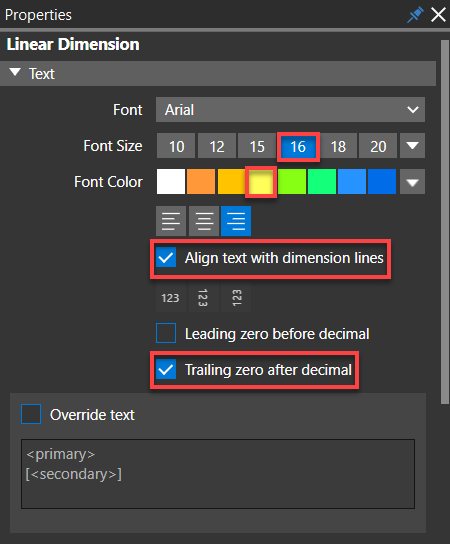
- Set the Font Size to 16 and Font Color to yellow in the Text pane.
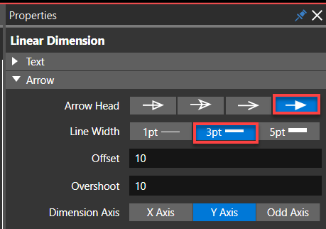
- In the Arrow pane:
- Change the Line Width from 1pt to 3pt . The width of the dimension line increases.
- Change the arrowhead to Solid Triangle Arrowhead.
- In the Unit pane
- Select the Secondary Units check box and choose a different unit of measurement to display the dimension value.
The secondary unit starts displaying below the primary units. - Set the Decimal Precision for the secondary units to set the accuracy as needed.
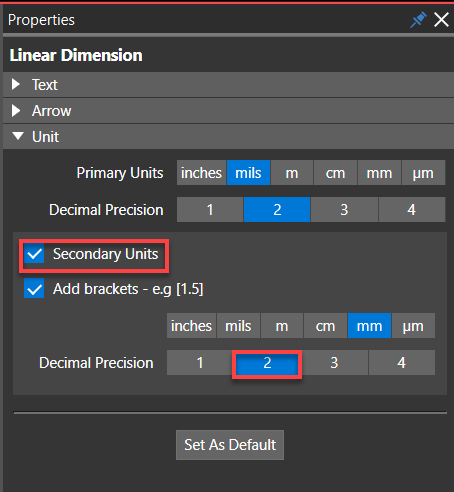
- Select the Secondary Units check box and choose a different unit of measurement to display the dimension value.
- In the Text pane:
- Modify dimension text using the following steps:
- Click the Override text check box to override the dimension text. You can add additional information with the dimension value. Use
and macros to control the display of dimension units. 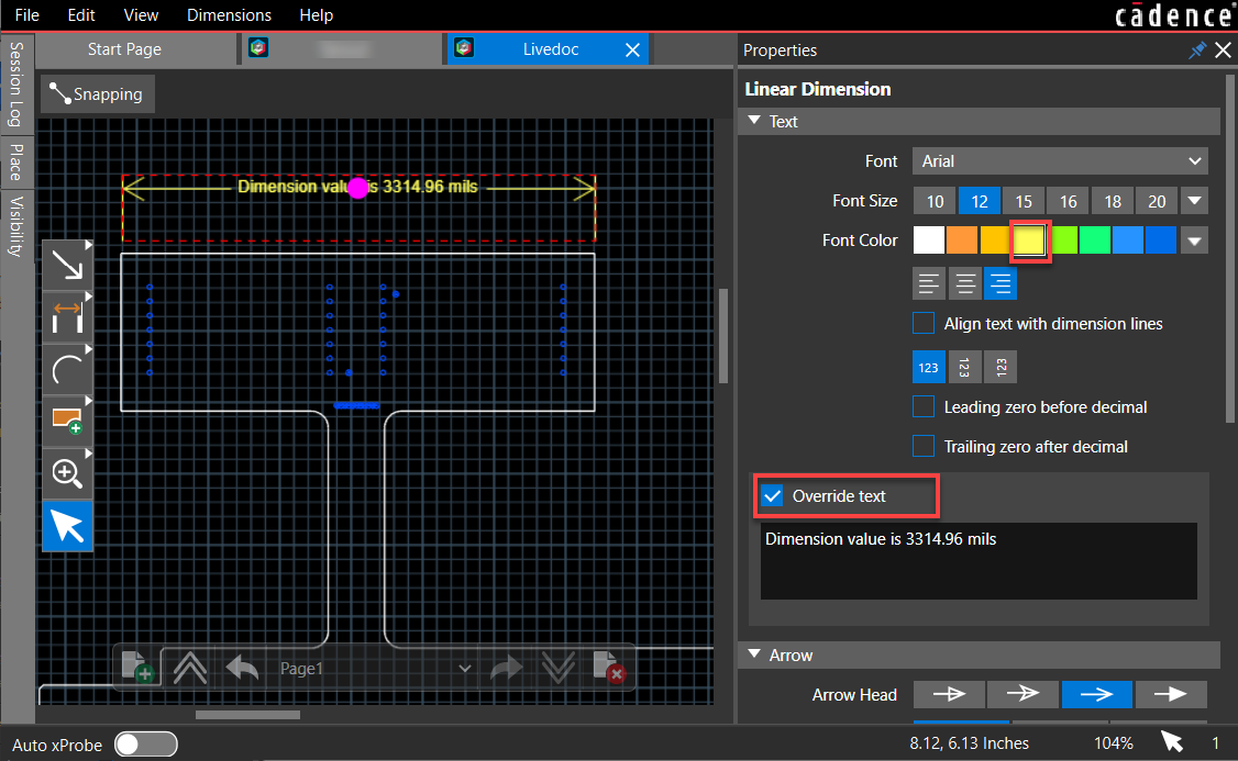
- Click Set as Default to add new linear dimensions with the same settings.
- Click the Override text check box to override the dimension text. You can add additional information with the dimension value. Use
- Modify the dimension line axis using the following steps:
- Select two points that are not on the same X-axis coordinates as illustrated in the following image:
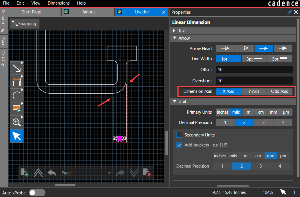
- Change the Dimension line axis to the Odd Axis.
Live Doc calculates and displays the distance between the points along the slanted axis.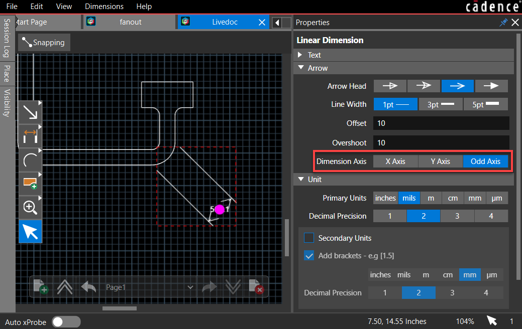
- Select two points that are not on the same X-axis coordinates as illustrated in the following image:
- To delete a dimension, select it and click the Delete button.
Adding Angular Dimensions
Angular dimensioning calculates the angle between two line segments. Angular dimension can be added and modified in the same way as a linear dimension using the following steps:
- Choose Dimensions – Angular or click the
 icon from the command toolbar.
 - Click the two line segments and choose a location to place the dimension text.
- Double-click to select the dimension to modify.
Two pink dots are displayed as guide points for the line and text, respectively.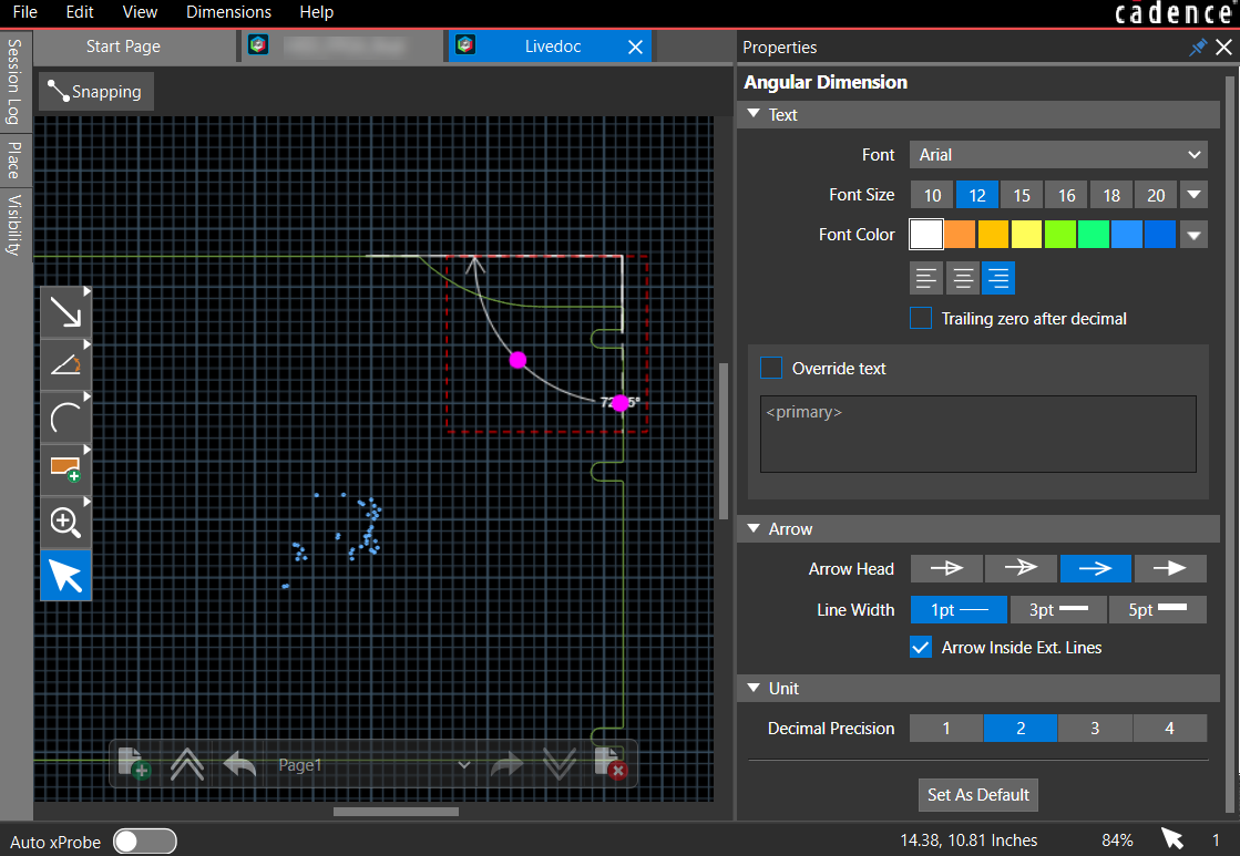
Moving the cursor in the inward or outward directions repositions the dimension line. Similarly, moving the cursor along the line repositions the dimension text.
Adding Ordinate Dimensions
The ordinate dimension is a set of multiple linear dimensions that adds dimensions relative to a reference point. The dimensions are placed at the end of a single extension line that can have multiple vertices and is useful to place on the outer edges of a board or object outlines.
- Choose Dimensions – Ordinate or click the
 icon from the command toolbar.
 - Select the first dimension point.
A white dot represents the reference point with x = 0 and y = 0 coordinates. - Click to add other dimension points.
- Double-click to place the dimension.
The other dimensions added are relative to the first point, as illustrated in the following image: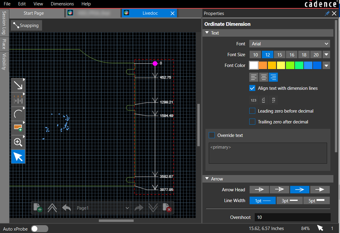
- To delete the dimension, select it and press the Delete button.
Adding Leader-Oriented Dimensions
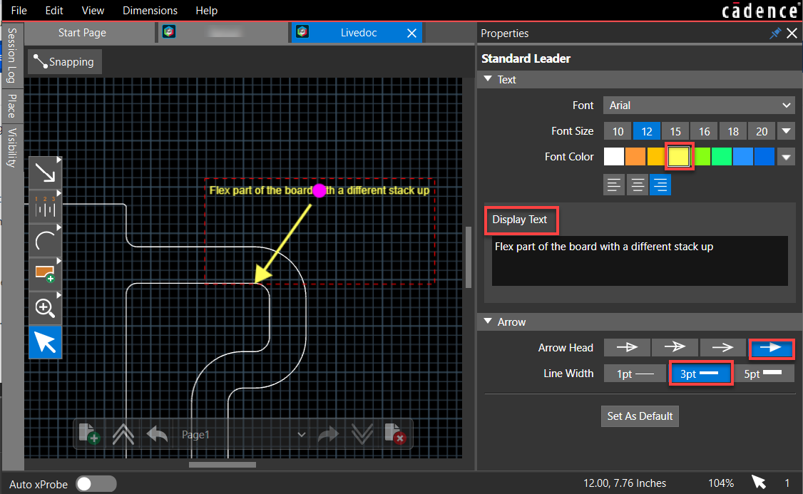
Live Doc allows standard leader lines to add a note or dimension to the drawing feature. Leaders are used for adding diametrical and radial dimensions and balloons. Leaders also provide an alternative method for dimensioning chamfers.
Live Doc provides options to add the following leader types:
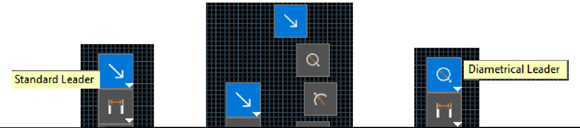
- Standard Leader: Adds standard leader lines with a note.
- Diametrical Leader: Adds dimension to circular objects.
- Radial Leader: Adds dimension to an arc or circle.
- Balloon Leader: Adds a leader line with a balloon at the other end, enclosing an alphanumeric character string.
- Chamfer Leader: Adds standard 45-degree chamfer drafting dimensions.
To add leaders in Live Doc to the objects, do the following:
- Choose the leader type from the Dimensions menu or click a leader icon in the functional toolbar.
- Position the cursor at a point on an element or in the canvas where you want the leader to point.
- Click the point on the canvas.
A white dot appears, representing the reference point. - Move the cursor and click again to establish the position and length of the leader. The leader is added to the canvas.
- Click the Select icon
 to display leader properties in the Properties panel.
 - Modify the leader text in the Display Text field in the Properties panel. The Properties panel displays the field to modify the default leader text.
- Select the relevant leader icon from the functional toolbar and repeat steps 2 to 6 to add more leaders.
Defining Annotations in Live Doc
You can point out a specific location of the design, add text, or custom images using graphical tools available in Live Doc. Various drawing tools are available in Live Doc to do the following tasks:
- Explicitly draw lines, polylines, and rectangles to create specific assembly instructions or to add inspection notes.
- Specify materials, processes, tolerances, or other design requirements saved as Live Doc data.
You can place various graphical objects from the functional toolbar, as illustrated in the following image: 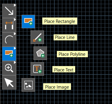
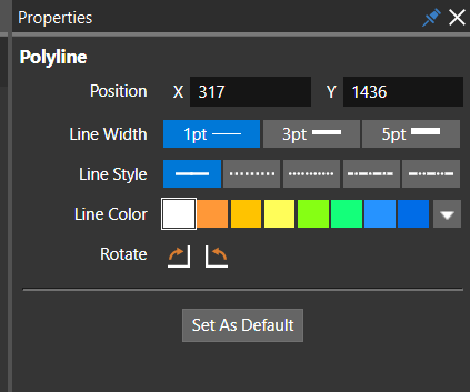
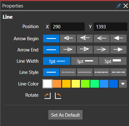
The Properties panel displays the attributes of the drawing object when selected in the Live Doc canvas. You can modify the line width, style, color, and orientation of a rectangle, polyline, or line object. 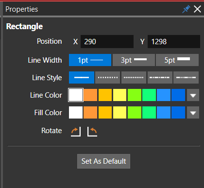
A text string can be placed directly into the Live Doc canvas using the Place Text icon from the command toolbar. You can add fabrication notes to the manufacturer by using the text option.
To place text in Live Doc, do the following:
- Select the Place Text icon from the command toolbar.
- Click to choose a location in the Live Doc canvas to place the text.
- Type the text string and click anywhere in the Live Doc canvas.
- Select the text using the select icon to modify the text's appearance, such as font, style, alignment, and orientation.
The attributes of the selected text string are displayed in the Properties panel and can be modified as required.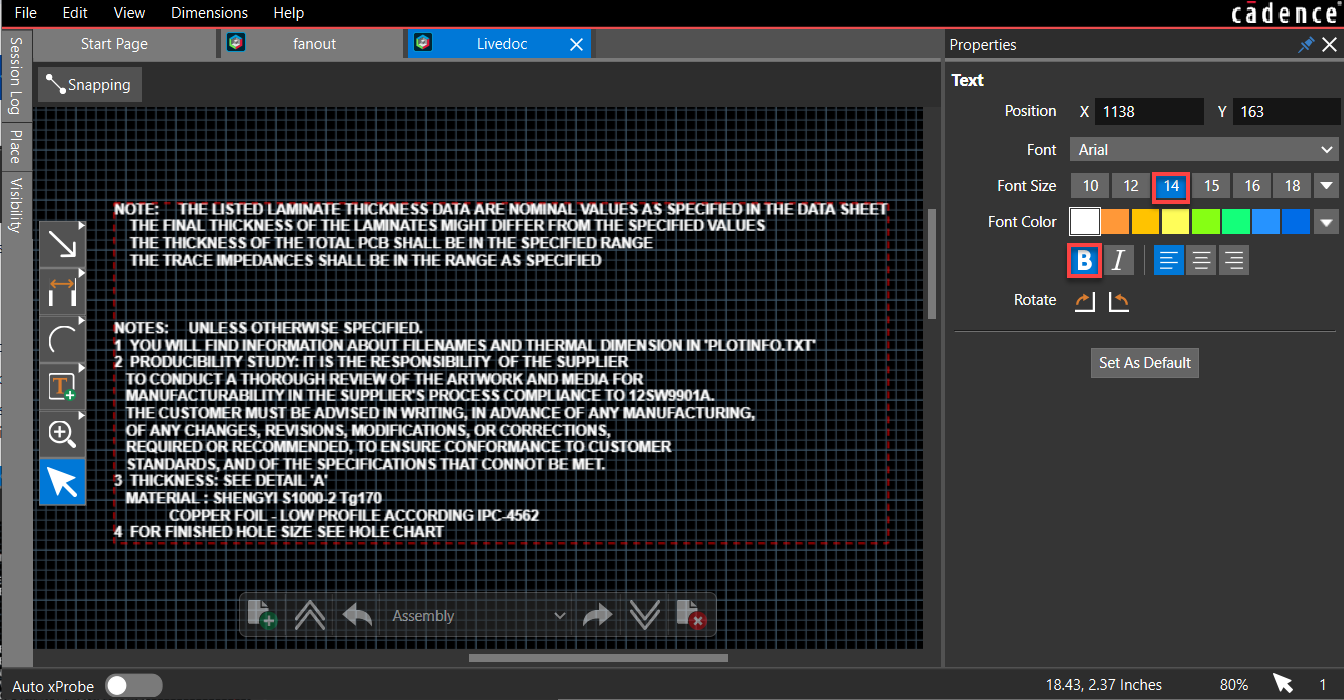
An image can be annotated in the Live Doc canvas. The supported file formats are .bmp, .jpg, .jpeg, and .png.
Managing Live Doc
Live Doc data is saved with the board design and can be accessed in multiple ways.
Moving Live Doc Tab to a New Workspace
Live Doc can work independently of the OrCAD X Presto user interface. The Live Doc tab can be moved to a new workspace. You can utilize this option to work simultaneously in the OrCAD PCB Editor X and Live Doc windows in a multi-monitor setup. To switch Live Doc workspace, do the following:
- Right-click the Live Doc tab and choose Dock To – New.
The new workspace opens in a separate window, and the title bar displays the workspace ID. - To move back to the main workspace, choose Live Doc – Dock To – MainWorkSpace.
Closing Live Doc
When you close the Live Doc tab, the Live Doc data is saved with the database. You can close the Live Doc tab in one of the following ways:
- Click the cross button on the Live Doc tab.
- Right-click the Live Doc tab and choose Close Tab.
- Close the board design tab.
Reopening Live Doc
To reopen an existing Live Doc view:
- Choose Manufacturing – Live Doc – Open.
Deleting Live Doc
Live Doc associated with the board design file (.brd) can be deleted from the active board design.
- Choose Manufacturing – Live Doc – Delete.
View the next document: 12 - Reviewing and Analyzing Designs in OrCAD X Presto
If you have any questions or comments about the OrCAD X platform, click on the link below.
Contact Us