10 - Routing Nets in OrCAD X Presto
OrCAD X Presto offers several routing features for interactive routing.
Moving Trace Segments in the Slide Mode
While interactively editing routed connections, moving a trace segment in a sliding mode ensures connectivity and prevents dynamic DRCs. A trace segment can be moved in the slide mode as well as in the select mode. The latter provides a quick way to move trace segments using the in-session slide mode settings. A trace segment connected to a via or a virtual point when moved using the select mode slides via or virtual point along with it.
To move a trace segment in the Select mode, do the following:
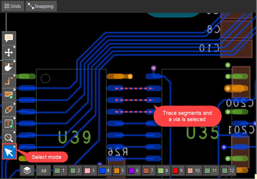
- Choose the Select icon in the command toolbar.
- Click to select a trace segment. You can choose multiple segments by pressing and holding the Control key or drawing a rectangle in the design canvas.
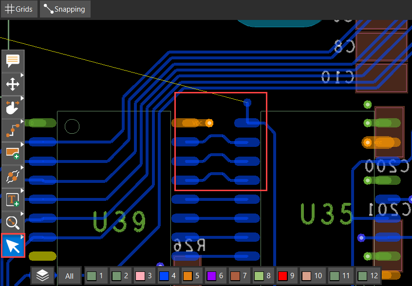
- Hold the mouse button and drag the mouse to slide the selected segments.
The selected segments are moved, maintaining connectivity. The components, if selected along with the segments, are not affected. DRCs
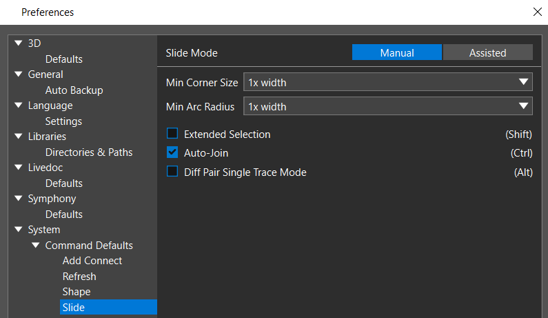
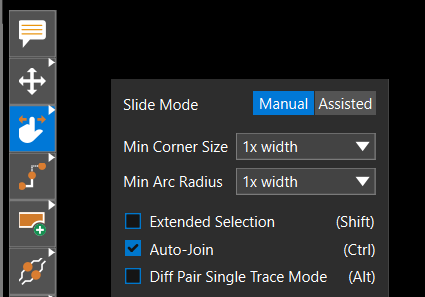
- Optionally, choose Edit – Preferences or select the Slide icon. Modify the default settings for the slide operation.
The select mode, when used to move trace segments, follows the modified settings of the slide command.
Resolving Timing Requirements with Delay Tuning
Meeting timing requirements is difficult and time-consuming in densely-populated boards. The Delay Tune command provides specialized tune bump patterns to match the signal lengths to resolve the timing requirements in a design.
The delay tune command is available only with the OrCAD X Presto Professional Layout license.
To add delay tune to a trace, do the following:
- From the floating command toolbar, right-click the Slide icon and click the Delay Tune icon.
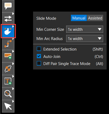
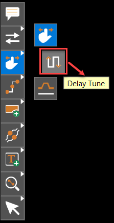 The Delay Tune widget opens with the default Manual mode, which displays the pattern details on the left and the bump parameter settings on the right.
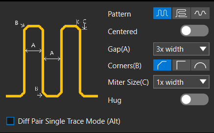
- In the Delay Tune widget, set up the tune parameters as follows:
- Click to choose a bump pattern icon from Accordion, Trombone, and Sawtooth. The selected pattern is highlighted in blue.
- Optionally, click to change the slider for generating centered bump patterns. The centered tune bump patterns have pattern entry and exit points at the center of the pattern.
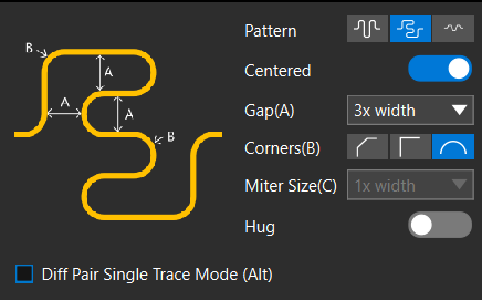
- Choose the tune gap parameter value from the Gap(A) list. It controls the inside spacing of the bump pattern.
- Click to select a tune corner icon for the Accordion and Trombone patterns. The three icons represent 45 degree, 90 degree, and Full Arc. This parameter is grayed out for the Sawtooth pattern.
- If you set a 45 degree corner for the chamfered Accordion and Trombone patterns, choose a value from the Miter Size(C) list. This parameter is grayed out for other patterns and corner settings.
- Optionally, enable Diff Pair Single Trace Mode to tune the select segment of a differential pair trace.
- Click to choose a trace segment in the design canvas.
- Position the cursor to define the length, height, and direction of the pattern.
A rectangle highlights the area to be used to generate the tuning bumps.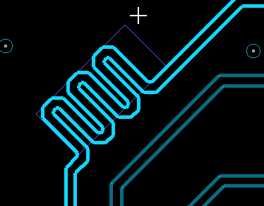
- Click again to define the rectangular area for creating the bump pattern.
The selected tune pattern is added to the trace and the Properties panel displays the global status of the design.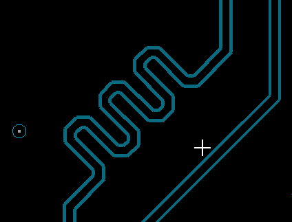
The Properties panel displays the location and general attributes of the selected trace segment along with the Heads Up Display that helps achieve the desired length. This real-time meter turns green when the desired length is met.
Splitting Stacked Vias
Stacked vias are used in place of through-hole vias by placing multiple vias on top of one another to reduce space and parasitic capacitance. A via stack is an arrangement of two or more same-net vias directly connected at the same location, with adjacent vias in the stack sharing one common layer. Sliding a via stack enables splitting the stack into a sub-stack or a single via. To split stacked vias, do the following:
- Click the Slide icon from the floating command toolbar. The Slide widget opens.
- Select stacked vias. Ensure that vias are enabled in the Selection Filter.
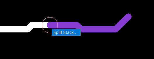
Stacked vias slide as a single object that includes a group of vias and their connections, regardless of the via selected in the stack. - Right-click and choose Split Stack.
Via selection window is displayed showing the stacked vias and the layer numbers.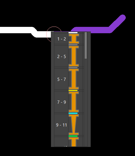
- In the via selection window, click to the right edge to choose a single via. To choose a range of vias, hold the left mouse button and click the vias.
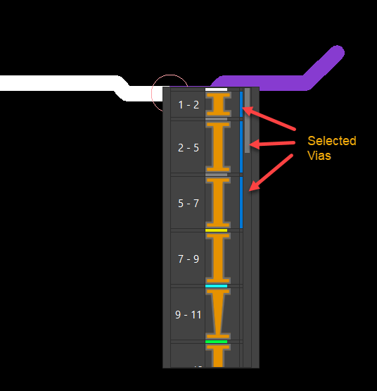
The selection of vias is indicated in blue. The selected via or via stack is separated from the master via stack and can be slid independently.
When sliding stacked vias outside the pin pad, a cline is added to prevent orphan vias or vias that disconnect from the net.
Using Structures for Quick Routing in OrCAD X Presto
In OrCAD X Presto, structures are reusable design elements created by combining vias, clines, static shapes, and route keepouts. Structures can be placed as a single entity in the same or different designs and can be managed quickly and simply.
The structure command is available only with the OrCAD X Professional licenses.
Creating Via Structures in OrCAD X Presto
Via structures are reusable design elements that combine vias, clines, static shapes, and route keepout shapes. Via structures are placed as symbols in the same or different designs and can be managed quickly and simply.
Prerequisite
- The command to create via structure is available only with the OrCAD X Professional licenses.
- Vias used for creating the structure symbol should be placed in the design or exist in the design library.
To create via structures, do the following:
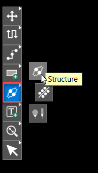
- From the floating command toolbar, right-click the Structure icon and select the Structure icon again from the displayed icons.
A widget opens with three functional tabs: Create, Generate, and Place. Guiding text is provided to help with the structure creation and placement. Blue text indicates the next step, green text indicates the action is completed, and gray text shows the step is incomplete.
- In the widget, specify a name for the structure or use the default name.
- Toggle the Cut by Rectangle option to include clines and line segments enclosed within a rectangle to select the objects to be combined as a structure. A new step, Draw cutting rectangle, is added to the workflow.
- Ensure that the visibility of clines and vias is set on all layers. Only visible objects are included in a structure.
- Enable the object types in the Selection Filter.
- Choose the elements of the structure by selecting vias and clines on the same net. To select multiple objects, click the items and then press and hold down the mouse button while moving the mouse.
Ensure that at least one via or cline is selected.
If the selected objects are connected to a pin, the command automatically determines the origin and start layer and creates the structure. - Select Cut by Rectangle if you enabled the Cut by Rectangle option. Draw a rectangle by selecting the start and end points with mouse clicks.
- If the selected objects are not connected to a pin, do the following:
- a. Click the center of the via or dangling cline end point to choose the origin of the structure.
- b. Select the start layer for the structure in the widget.
The structure created is saved in the design database, and the widget displays a new option, Create Another Structure, at the bottom.
Placing Via Structures in OrCAD X Presto
Via structures provide a quick way of adding and replacing the required pieces of etch in a design.
Prerequisite
The command to create via structure is available only with the OrCAD X Presto Professional licenses.
To place a via structure in a design, do the following:
- From the floating command toolbar, right-click the Structure icon and select the Structure icon again from the displayed icons.
- Click the Place tab in the Structure widget.
- Select a structure from the Structure list. The list displays all the structures saved with the design database.
The selected structure attaches to the cursor at the structure’s origin point. The widget starts displaying the names and colors of the layers the structure exists on from the Visibility panel.
- Optionally, enable the Add to Unassigned Pins check box to allow the structure to be attached to the elements not assigned to a net.
- Specify an angle to rotate the structure or toggle the Align With Selection option to align the structure with a pin.
- Click to choose a pin to attach the structure. To attach a structure to multiple pins, press and hold down the mouse button while moving the mouse to create a window.
- Keep selecting pins in the design canvas to place the structure.
- Optionally, to snap the structure only to pins, vias, or clines, enable the Snap to Selection check box. By default, this option is not selected, and you can place the structure anywhere in the design.
Editing Via Structures in OrCAD X Presto
Via structures are placed as symbols in a layout and can be modified during the course of the design cycle. A via structure can be modified in multiple ways.
Prerequisite
The command to create via structure is available only with the OrCAD X Presto Professional licenses.
The following methods can be used to edit via structures in a design.
Editing Via Structure Instance
To edit a specific instance of a via structure, follow these steps:
- Select the symbol from the Search panel or in the design canvas.
- In the Properties panel, toggle the Edit Instance option.
This action unlocks the structure symbol and enables it for editing.
- Modify the structure definition by adding, deleting, or sliding the trace segments.
Redefining a Via Structure
You can update the definition of all the placed instances to match the selected via structure using the Redefine command, as follows:
- Select a structure symbol.
- To modify the structure definition, toggle the Edit Instance option in the Properties panel.
- Apply interactive commands to any of the objects that belong to a structure. For example, slide, move, rotate, mirror, and delete.
- Right-click a structure symbol and choose Redefine.
- Click Yes in the confirmation dialog box to refresh all instances to match the new definition.
Disbanding a Via Structure
A via structure can be broken into its individual objects.
- To disband a structure, right-click a structure symbol and choose Disband structure. The structure is converted into individual clines, vias, and shapes.
Deleting a Via Structure
- To delete a via structure, right-click and choose Delete.
View the next document: 11 - Documenting the PCB with Live Doc in OrCAD X Presto
If you have any questions or comments about the OrCAD X platform, click on the link below.
Contact Us