20 - Managing Toolbars
Overview
The toolbars provide easy access to common actions. Each toolbar contains buttons that related to the specific functional group, such as PSpice toolbar. If you need more clear space on the screen to
view your work, you can hide a toolbar, anddisplay it again when you wish to use one of the tools. All the tools on the toolbar are available as menu commands.
Displaying a Toolbar
To display a toolbar, do the following:
- Choose the View – Toolbar menu command
- Select the required toolbar from the submenu.
Alternatively, right-click the menu bar at the top of the Capture screen and select the required toolbar.
Similarly, to hide a toolbar being displayed, select it from the View – Toolbar menu.
Moving a Toolbar
To move a toolbar anywhere on the screen, press the left mouse button over the toolbar and move the mouse to the new location of the toolbar.
If you move the toolbar to an edge of the session frame, it snaps into place along the side of the window. Otherwise, it floats on the screen wherever it is released.
When you move the pointer over an icon on the toolbar, a tooltip displays its name.
Align Toolbar
The Align toolbar offers a quick and easy way to align selected objects vertically (top, middle, and bottom) or horizontally (left, center, and right) with reference to other object. It also provides an option to equally distribute selected objects horizontally or vertically across a schematic page.
You can also align selected objects with reference to a mouse click or equally distribute the selected objects within the area defined by mouse clicks using Mouse Mode.
| Icon |
Name |
Description |
|
|
Align Left |
Use this command to left align the selected objects with respect to the leftmost selected object. |
|
|
Align Center |
Use this command to center align the selected objects with respect to the virtual selection bounding box. The virtual selection bounding box is formed with respect to the leftmost object and the rightmost object of the selected objects. |
|
|
Align Right |
Use this command to right align the selected objects with respect to the rightmost selected object. |
|
|
Align Top |
Use this command to top align the selected objects with respect to the topmost selected object. |
|
|
Align Middle |
Use this command to middle align the selected objects with respect to virtual selection bounding box. The virtual selection bounding box is formed with respect to the topmost object and the bottommost object of the selected objects. |
|
|
Align Bottom |
Use this command to bottom align the selected objects with respect to the bottommost selected object. |
|
|
Distribute Horizontal |
Use this command to horizontally distribute the selected objects with equal spacing within virtual selection bounding box. The virtual selection bounding box is formed with respect to the leftmost object and the rightmost object of the selected objects. |
|
|
Distribute Vertical |
Use this command to vertically distribute the selected capture objects with equal spacing within virtual selection bounding box. The virtual selection bounding box is formed with respect to the topmost object and the bottommost object of the selected objects. |
|
|
Mouse Mode |
Use this command to enable or disable Mouse Mode. |


Capture Toolbar
The Capture toolbar provides shortcuts for many of the most frequently used generic Capture commands. The following table describes the icons on the toolbar.
| Icon |
Name |
Description |
|
|
Create document |
Creates a new document based on the active document. Equivalent to the New command on the File menu. |
|
|
Open document |
Opens an existing document based on the active document. Equivalent to the Open command on the File menu. |
|
|
Save document |
Saves the active schematic page or part. Equivalent to the Save command on the File menu. |
|
|
|
Prints the active schematic page or part. Equivalent to the Print command on the File menu. |
|
|
Cut to clipboard |
Removes the selected object and places it on the Clipboard. Equivalent to the Cut command on the Edit menu. |
|
|
Copy to clipboard |
Copies the selected object to the Clipboard. Equivalent to the Copy command on the Edit menu. |
|
|
Paste from clipboard |
Pastes the contents of the Clipboard at the cursor. Equivalent to the Paste command on the Edit menu. |
|
|
Undo |
Undoes the last command performed. Equivalent to the Undo command on the Edit menu. |
|
|
Redo |
Redoes the last command performed. Equivalent to the Redo command on the Edit menu. |
|
|
Snap to grid |
|
|
|
Area Select - Fully Enclosed Vs Intersecting |
If the button is in the Enclosed mode state, ensure that the object along with its name and number are enclosed in the selection area. Otherwise, the object does not get selected. |
|
|
|
|
|
|
Most recently used |
Displays the most recently placed part name in the drop-down list. Capture automatically adds part names as you select them from the Place Part dialog box. Select from the list to place parts again later. |
|
|
Zoom in |
Zooms in to present a closer, enlarged view. Equivalent to the In command on the Zoom menu (on the View menu). |
|
|
Zoom out |
Zooms out to present more of your document. Equivalent to the Out command on the Zoom menu (on the View menu). |
|
|
Zoom to region |
Specifies an area of the schematic page or part to enlarge to fill the entire window. Equivalent to the Area command on the Zoom menu (on the View menu). |
|
|
Zoom to all |
Views the entire document. Equivalent to the All command on the Zoom menu (on the View menu). |
|
|
Fisheye |
Toggles the Fisheye mode on and off. |
|
|
Project manager |
Displays a project manager window for the active document, providing an overview of project contents. |
|
|
Help |
Displays the online help. Equivalent to the Help Topics command on the Help menu. |
|
|
Annotate |
Assigns part references to parts on the selected schematic pages. Equivalent to the Annotate command on the Tools menu. |
|
|
Backannotate |
Back annotates the selected schematic pages. Equivalent to the Back Annotate command on the Tools menu. |
|
|
Create netlist |
Creates a netlist from the selected design. Equivalent to the Create Netlist command on the Tools menu. |
|
|
Cross reference parts |
Creates a cross reference report of the selected schematic pages. Equivalent to the Cross Reference command on the Tools menu. |
|
|
Bill of materials |
Creates a bill of materials report from the selected schematic pages. Equivalent to the Bill of Materials command on the Tools menu. |


 , then Capture allows you to place or move objects anywhere on the page.
 , the objects are selected when the selection area border intersects them.
 , the objects are selected only when they are completely enclosed in the selection area.
 state then the selected object attaches to the cursor and does not get placed on the schematic, if it changes the connectivity.


Draw Electrical Toolbar
The Draw Electrical toolbar provides shortcuts for commands to place components, pins, wires, and bus. The following table describes the icons on this toolbar.
| Icon |
Name |
Description |
|
|
Select |
Selects objects. This is the normal mode. |
|
|
Place part |
Selects parts from a library for placement. Equivalent to the Part command on the Place menu. |
|
|
Place wire |
Draws wires. Shift allows any angle drawing. Equivalent to the Wire command on the Place menu. |
|
|
Place NetGroup | Places a net group. |
|
|
Auto Connect two points |
Switches the Schematic page editor into the Auto connect mode and allows you to connect two points on the page. |
|
|
Auto Connect multi points |
Switches the Schematic page editor into the Auto connect mode and allows you to connect multiple points on the page. |
|
|
Auto Connect to Bus |
Switches the Schematic page editor into the Auto connect mode and allows you to connect points to a bus. |
|
|
Place net alias |
Places aliases on wires and buses. Equivalent to the Net Alias command on the Place menu. |
|
|
Place bus |
Draws buses. Shift allows any angle drawing. Equivalent to the Bus command on the Place menu. |
|
|
Place junction |
Places or deletes junctions. Equivalent to the Junction command on the Place menu. |
|
|
Place bus entry |
Draws bus entries. Equivalent to the Bus Entry command on the Place menu. |
|
|
Place power |
Places power symbols. Equivalent to the Power command on the Place menu. |
|
|
Place ground |
Places ground symbols. Equivalent to the Ground command on the Place menu. |
|
|
Place hierarchical block |
Places hierarchical blocks. Equivalent to the Hierarchical Block command on the Place menu. |
|
|
Place port |
Places hierarchical ports on schematic pages. Equivalent to the Hierarchical Port command on the Place menu. |
|
|
Place H pin |
Places hierarchical pins in the selected hierarchical block. Equivalent to the Hierarchical Pin command on the Place menu. |
|
|
Place pin |
Places a pin on the schematic page. |
|
|
Place off-page connector |
Places off-page connectors. Equivalent to the Off-Page Connector command on the Place menu. |
|
|
Place no connect |
Places no-connect symbols on pins. Equivalent to the No Connect command on the Place menu. |
|
|
Place IEEE Symbol |
Places IEEE symbols. Equivalent to the IEEE Symbol command on the Place menu. This command is available in the Part Editor. |
|
|
Place Pin Array |
Places pin arrays. Equivalent to the Pin Array command on the Place menu. This command is available in the Part Editor. |


Draw Graphical Toolbar
The Draw Graphical toolbar provides shortcuts for commands to drawing objects, such as arcs, polyline, ellipse, and text. The following table describes the icons on this toolbar.
| Icon |
Name |
Description |
|
|
Place line |
Draws lines. Equivalent to the Line command on the Place menu. |
|
|
Place polyline |
Draws polylines. shift allows any angle drawing. Equivalent to the Polyline command on the Place menu. |
|
|
Place rectangle |
Draws rectangles. shift constrains the shape to a square. Equiva-lent to the Rectangle command on the Place menu. |
|
|
Place ellipse |
Draws ellipses. shift constrains the shape to a circle. Equivalent to the Ellipse command on the Place menu. |
|
|
Place arc |
Draws arcs. Equivalent to the Arc command on the Place menu. |
|
|
Place elliptical arc |
Draws elliptical arcs. Equivalent to the Elliptical Arc command on the Place menu. |
|
|
Place Bezier |
Draws bezier curves. Equivalent to the Bezier Curve command on the Place menu. |
|
|
Place text |
Places text. Equivalent to the Text command on the Place menu. |


Part Manager Toolbar
The Part Manager toolbar offers a quick and easy way to perform common tasks. This toolbar is active only when you open OrCAD X Capture CIS. The following table describes the icons on the toolbar.
| Icon |
Name |
Description |
|
|
Link Database Part |
Links a part from the database to a schematic part. Equivalent to the Link Database command on the Tools menu. |
|
|
Update All Part Status |
Checks all parts against the parts database. Equivalent to the Update All Part Status command on the Tools menu. |
|
|
Bill of materials |
Creates a bill of materials. Equivalent to the Standard command on the CIS Bill of Materials sub-menu of the Reports menu. |
|
|
Crystal Reports bill of materials |
Generates bill of materials using Crystal Reports interface. Equivalent to the Crystal Reports command on the CIS Bill of Materials sub-menu of the Reports menu. |
|
|
Variant Report |
Generates a variant report. Equivalent to the Variant command on the Reports menu. |
|
|
Expand/Collapse Tree Item |
Expands or collapses the tree view. Equivalent to the Expand/collapse tree item command on the View menu. |
|
|
Show/Hide Tree View |
Shows or hides the tree view. Equivalent to the Show/Hide tree view command on the View menu. |
|
|
Resolve Ambiguity |
Resolves ambiguity for selected item. Equivalent to the Resolve ambiguity command on the Tools menu. |


PCB Toolbar
The PCB toolbar for the PCB flow available in Capture provides shortcuts for many of the most frequently used commands. The following table describes the icons on the toolbar.
| Icons |
Name |
Description |
|
|
Open Active Layout |
Opens the active board file in the layout tool selected in the Design Sync Setup dialog box. |
|
|
Open Update Layout |
Opens the Update Layout dialog box, which allows you to view and then commit to design connectivity changes in real-time from Schematic to Layout. |
|
|
Open Update Schematic | Opens the Update Schematic dialog box, which allows you to view and then commit to design connectivity changes in real-time from Layout to Schematic. |
|
|
Launch Constraint Manager |
Opens the information window that explains the Capture-Constraint Manager flow. |
|
|
Design rules check |
Opens the Design Rules Check window to run checks to identify design rules violations. Checks for design rules violations in the selected schematic pages. Equivalent to the Design Rules Check command on the Tools menu. |


PSpice Toolbar
The PSpice toolbar provides shortcuts for many of the most frequently used PSpice commands. This toolbar appears only if you have PSpice license and open a project that uses PSpice. The following table describes the icons on the toolbar.
| Icon |
Name |
Description |
|
|
New simulation profile |
Creates a new simulation profile. Equivalent to the New Simulation Profile command on the PSpice menu. |
|
|
Edit simulation profile |
Opens simulation profile for editing. Equivalent to the Edit Simulation Profile command on the PSpice menu. |
|
|
Run PSpice |
Runs PSpice simulation for active profile. Equivalent to the Run PSpice command on the PSpice menu. |
|
|
View Simulation Results |
Shows simulation results for the active profile. Equivalent to the View Simulation Results command on the PSpice menu. |
|
|
Launch PSpice Part Search | Opens the PSpice Part Search pane. |
|
|
Modeling Applications | Opens the Modeling Application pane. |
|
|
Voltage/Level Marker |
Places voltage/digital level markers. Equivalent to the Voltage Level command on the Markers submenu of the PSpice menu. |
|
|
Voltage Differential Marker |
Places voltage differential marker. Equivalent to the Voltage Differential command on the Markers submenu of the PSpice menu. |
|
|
Current Marker |
Places marker showing current into a pin. Equivalent to the Current Into Pin command on the Markers submenu of the PSpice menu. |
|
|
Power Dissipation Marker |
Places marker showing power dissipation of a device. Equivalent to the Power Dissipation command on the Markers submenu of the PSpice menu. |
|
|
Displays a list of Plot Window Templates |
Displays a list of Plot Window Templates available for marker placement. Equivalent to the Plot Window Template command in the Markers submenu of the PSpice menu. |
|
|
Enable Bias Voltage Display |
Enables display of bias voltages. Equivalent to the Enable Bias Voltage Display command on the Bias Points submenu of the PSpice menu. |
|
|
Toggle Voltages on Selected Net(s) |
Toggles display of voltage bias point value for selection. Equivalent to the Toggle Selected Bias Voltage Display command on the Bias Points submenu of the PSpice menu. |
|
|
Enable Bias Current Display |
Enables display of bias currents. Equivalent to the Enable bias current display command on the Bias Points submenu of the PSpice menu. |
|
|
Toggle Currents on Selected Part(s)/Pin(s) |
Toggles display of current bias point value for selection. Equivalent to the Toggle Selected Bias Current Display command on the Bias Points submenu of the PSpice menu. |
|
|
Enable Bias Power Display |
Enables display of bias point quiescent power. Equivalent to the Enable bias power display command on the Bias Points submenu of the PSpice menu. |
|
|
Toggle Power on Selected Part(s) |
Toggles display of bias point quiescent power for selection. Equivalent to the Toggle bias power command on the Bias Points submenu of the PSpice menu. |
|
|
Assigns Tolerance for Advanced Analysis |
Opens the Tolerance Analysis window. Equivalent to the Assign Tolerance command on the Advanced Analysis submenu of the PSpice menu. |
|
|
Start Advanced Analysis - Sensitivity |
Enables Sensitivity Analysis in PSpice Advanced Analysis. Equivalent to the Sensitivity Analysis command in the Advanced Analysis submenu of the PSpice menu. |
|
|
Start Advanced Analysis -Optimizer |
Enables Optimizer Analysis in PSpice Advanced Analysis. Equivalent to the Optimizer Analysis command in the Advanced Analysis submenu of the PSpice menu. |
|
|
Start Advanced Analysis - Monte Carlo |
Enables Monte Carlo Analysis in PSpice Advanced Analysis. Equivalent to the Monte Carlo Analysis command in the Advanced Analysis submenu of the PSpice menu. |
|
|
Start Advanced Analysis - Smoke |
Enables Smoke Analysis in PSpice Advanced Analysis. Equivalent to the Smoke Analysis command in the Advanced Analysis submenu of the PSpice menu. |
|
|
Start Advanced Analysis - Parametric Plot |
Enables Parametric Plot Analysis in PSpice Advanced Analysis. Equivalent to the Parametric Plot Analysis command in the Advanced Analysis submenu of the PSpice menu. |


SI Analysis Toolbar
The SI Analysis toolbar for SI Analysis functions available in Capture provides shortcuts for many of the most frequently used SI Analysis commands. The following table describes the icons on the toolbar.
| Icon |
Name |
Description |
|
|
SI Library Setup |
Opens the Library Setup (SI Analysis) window to set the DML libraries. |
|
|
Auto Assign Discrete SI Models |
Assigns discrete SI models to the design parts. |
|
|
Identify DC Nets in the Design | Identify all DC nets in the design and assign voltage property. |
|
|
Assign SI Model |
Opens the SI Model Assignment window where you can assign models from the listed libraries. You can also autogenerate models. |
|
|
Explore Signal |
Opens SigXplorer to explore the signal. |
|
|
Export Topology | Export Topology dumps a .top file for a selected net which needs to be used by SigXP for launching. |
|
|
Export Electrical Csets |
Opens the Export Electrical Csets from design window. You can export a topology file that can then be updated using SigXPlorer offline in a distributed design environment. |
|
|
Import Electrical Csets |
Opens the Select Directory window where you can specify the directory from where you want to import an Electrical Cset. |
|
|
Remove Electrical Cset Assignments |
Opens the Remove ECSets from design window where you can selectively remove existing Electrical Csets from the design. |
|
|
Associate Electrical Cset |
Associates an Electrical Csets using a topology file. |
|
|
Validate Electrical Cset Assignments |
Opens the Validate ECSets in design window where you can selectively validate Electrical Csets in the design. |
|
|
Validate SI Model Assignments |
Validates the SI model assignments. |
|
|
SI Model Integrity |
Opens Model Integrity with the DML file for the devices. |
|
|
Export SI Models Used |
Exports the SI models used in the design into a DML library file. |
|
|
Remove SI Model Assignments |
Removes SI model assignments. |


Customizing Toolbars
You can customize the toolbars to alter the look and feel of the toolbar buttons, to create custom toolbars, or even add and remove buttons from the existing toolbars.
Changing the Display
To change the display of toolbars, do the following:
- Select Tools – Customize.
- Click the Toolbars tab.
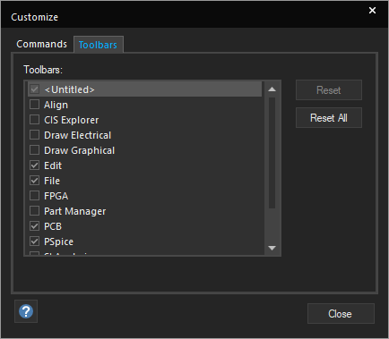
- Select the toolbars you want to display from this list.
The selected toolbar appears. - Click Close.
Alternatively, you can open the Customize dialog box using one of the following methods:
- Choose View – Toolbar – Customize.
- Right-click any menu bar or toolbar and choose Customize.
Adding Menus and Toolbar Icons
To add a menu command or a toolbar button as a new menu or in the toolbar, do the following:
- Select Tools – Customize.
- In the Commands tab, from the Categories list, select a category to display the related toolbar or menu bar options.
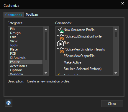
- To add the selected option to a toolbar or to a menu, drag it from the Customize dialog box to any toolbar or menu bar displayed in the program window.
- Click Close to close the dialog box.
- To remove buttons from toolbars, drag the button away from the toolbar.
Resetting Toolbars to Default
To reset toolbars to their default settings, do the following:
- Select Tools – Customize.
- Click the Toolbars tab.
- Click Reset.
- Click Close.
Changes are applied only to the currently selected toolbar.
Docking Toolbars
The toolbars in Capture can be docked, or made floating. This gives you the flexibility of placing the toolbar anywhere on the screen. You can place a floating toolbar even outside the application area.
- To make a toolbar floating, keeping the left mouse button pressed, drag the toolbar to the desired location on the application. Ensure that you do not click any of the toolbar buttons.
- To dock a floating toolbar, double-click its title bar.
- To move a floating toolbar, click the title bar and keeping the left mouse button down, drag the toolbar.
- To hide a toolbar, click the close (X) button on the right side of the title bar.
- To hide a toolbar, you can also right-click any toolbar or menu bar and deselect the toolbar name from the shortcut menu.
View the next document: 21 - Shortcut Keys
If you have any questions or comments about the OrCAD X platform, click on the link below.
Contact Us