09 - Working with Properties
Overview
OrCAD X Capture uses properties to describe objects. Imagine a brown, ceramic capacitor that measures 6 millimeters in height. Type, color, and height are properties, while ceramic, brown, and 6 millimeters are property values. Every Capture object is made up of such name-and-value pairs.
_# to one of two properties, where # is the counting number that makes the name unique on the object.Types of Properties
Inherent and User-Defined Properties
Some properties, called inherent properties, are an essential part of an object; others, called user-defined properties, are not used by Capture, but may be used by another tool. For example, if you want to include the supplier and the price per hundred for the objects on your schematic pages, you create two user-defined properties for the objects. You can add as many user-defined properties to objects as required and remove these properties when you no longer need them. Graphic objects such as lines, ellipses, and rectangles do not support user-defined properties.
Creating and Adding Properties
When you create a user-defined property with the Edit Part Properties dialog box, you can make the property name visible and specify the font and location of the property value text, even before you specify the property value. The property name acts as a placeholder until you supply the property value.
When you add a user-defined property to an existing object using the property editor, you can assign the property value at the time you create the new property or later. The additional benefit to using the property editor is the flexibility with which you can edit all properties on an object or group of objects on a schematic page.
Once you have added properties to a part on a schematic page, its properties no longer match the properties of the same part residing in the library. This part on the schematic page is unique, in that it has properties assigned specifically to it that are not inherited from the library part definition.
The property editor window shows you all available properties in the new single view. You can use the tabs to edit properties of all selected objects from the property editor. The property editor also displays all library definitions, instance properties, and occurrence properties for an object.
Properties in the Design Cache
When a part is first placed on a schematic page, a copy of the part and its library properties is put into the design cache from the library. A few of the library properties, such as PCB Footprint and Value, are also copied as instance properties onto the placed part. The rest of the library properties override or shine through from the cache to the instance and occurrence of the part property.
An overriding value or shine through property is indicated by hash marks in the cell. In the property editor, you can assign an instance or occurrence value, creating an instance or occurrence property. This instance or occurrence property then overrides the shine through value.
Instance Property
An instance property is a user property applied to the placed instance of a part or symbol in the design. This includes PCB Footprint, Value, and Name properties of each placed part or symbol in a design. This is the same as the user properties displayed and editable from the Capture Logical view.
An instance property shines through to all occurrences of that instance unless it is overridden by occurrence properties that you have explicitly edited. A change using any of the tools, such as Annotate, also updates the instance property.
Occurrence Property
An occurrence property is a user-defined property applied to a particular occurrence of a placed instance of a part or symbol in a design. The spreadsheet expands to display occurrence properties if values are different from the instance shine through value; otherwise, the rows are hidden from view. To hide or display all the occurrence properties quickly, press and hold the CTRL key while clicking one of the plus (+) symbols in the property editor.
Push Occurrence Properties into Instance Utility
If you copy a circuit or part of a circuit from design A and paste it in design B, you might see occurrence and instance level properties with different values on the pasted parts in design B. Instead of invoking the property editor on each part, copying and pasting the occurrence property values of the Part Reference, PCB Footprint property and any other property as instance property values, and then removing occurrence properties, you can use the Push Occurrence Properties into Instance utility to automatically do this.
This utility automatically:
- transfers occurrence property values of the part reference and PCB footprint properties as instance-level property values
- removes all occurrence properties from the design and sets the preferred mode of the design to instance (if you select the Remove occurrence level properties check box).
- transfers occurrence property values of flat nets to schematic nets.
To run this utility, Choose the Accessories – Push Occ. Prop into Instance menu command, and then choose Transfer Occ. Prop. to Instance.
The Push Occ. properties to instance dialog box is displayed.
Combined Property Strings
With many of the tools in Capture, such as Create Netlist and Annotate, you use combined property strings to convey information to the tool or to limit the tool's action.
A combined property string consists of one or more property names, enclosed in braces, and can also contain literal text. Capture combines the values of the named properties with any literal text to create a string. An example is:
{Value}{Reference}
where "Value" and "Reference" are property names. Using this combined property string and a part with a part value of 74LS32 and a part reference of U?A, Capture creates the string:
74LS32U?A
You can include spaces and other characters in the combined property string, as in this example:
Part: {Value} ({Reference})
Using this combined property string and the same part, Capture creates the string:
Part: 74LS32 (U?A)
Different tools use combined property strings in different ways. For example, Annotate uses one to compare parts---if one part's combined property string matches another part's combined property string, it packages the parts together.
Bill of Materials and other commands on the Tools menu that generate an output file based on a combined property string may produce errors if you include extra curly braces.
You can include tabs in combined property strings, so that the output file can be manipulated in a spreadsheet or database application. Tabs also help format report files, such as those created by the Bill of Materials command.
Wherever you want to have a tab in the output file, insert the characters \t (a backslash and a lowercase "t") in the combined property string.
Certain properties can be edited, but not removed. These are called inherent properties and are listed in the following table:
Inherent Properties
|
Object Type |
Properties |
|---|---|
|
Arcs |
Line style and width, color |
|
Bookmarks |
Name |
|
Images (pictures) |
(None) |
|
Bus entries |
ID, net name |
|
Buses |
(None) |
|
DRC markers |
(None) |
|
Ellipses |
Fill style, line style and width, color |
|
Ground symbols |
Name |
|
Hierarchical pins |
Name, pin type, pin width |
|
Hierarchical ports |
Name, pin type |
|
Hierarchical blocks |
Color, implementation path, implementation type, implementation, name, primitive, part reference, value |
|
IEEE symbols |
(None) |
|
Junctions |
(None) |
|
Lines |
Line style and width, color |
|
Net aliases |
Alias name, color, rotation, font |
|
No connect objects |
(None) |
|
Off-page connectors |
Name |
|
*Pictures (*images) |
(None) |
|
Pins in part editor |
Name, number, width, shape, type |
|
Pins in schematic page editor |
Is no connect, name, net name, number, order, swap ID, type |
|
Polygons |
Fill style, line style and width, color |
|
Polylines |
Line style and width, color |
|
Power symbols |
Name |
|
Rectangles |
Fill style, line style and width, color |
|
Title blocks |
Design create time, design file name, design modify time, design name, page create date, page modify date, page size, schematic create date, schematic modify time, schematic name, schematic page count, schematic page number, source library, source symbol |
|
Text |
Text content, color, rotation, font |
|
Visible properties |
Value (of most properties), visibility, color, font, rotation |
|
Wires |
ID, net name |
Defining Properties
All objects are described by properties to which you can assign values to suit your needs. In addition, you can add to the set of properties for the object types listed below.
- Parts
- Hierarchical blocks
- Pins on library parts
- Buses
- Wires
For nets, you actually select a wire segment and add a property, but the property exists on the net rather than on the individual wire segment.
You can add a property and specify the color, visibility, and font of the property text without assigning a value. The property name, which serves as a placeholder, appears next to the object and is enclosed in braces.
Adding a User-Defined Property
To add a user-defined property in Property Editor, do the following:
- Select an object on a schematic page.
- Right-click the object and choose Edit Properties from the pop-up menu.
The Property Editor for the object opens.
Note: The Property Editor displays a number of properties of the object. These are the system-defined properties for the object. - To add a user-defined property, click the New Property button on the top left corner of the Property Editor window.
-
In the Add New Property dialog box, specify a name and value for property.
A property value is not mandatory. This means that you can create a property with only a name.
- To save this property and add a new property click Apply.
OR
Click OK to save this property and close the dialog box.
The new property is added in the Property Editor window. - To change the display properties of a property, right-click the property row or column and choose Display.
The Display Properties dialog box displays.
In this dialog box, you can choose the display options:- Not to display the property on the schematic page
- Display only the value or only the name
- Display both value and name
- Click OK.
Creating a New Property in the Browse Spreadsheet Editor
To create a new property in the Browse spreadsheet editor, do the following:
- In the first column of the Browse spreadsheet, select the object or occurrence for which you want to create the new property.
- From the Edit menu, choose Properties. Capture displays the object in a new Browse spreadsheet window.
- Click New. Capture displays the New Property dialog box.
- Enter a name and value for the new property, then click OK. Capture adds the property to the object or occurrence and displays the property in the original Browse spreadsheet.
Types of Filters
You can constrain the set of displayed properties by using the filters available in the drop-down list in the upper right corner of Property Editor. A number of filters are available. These filters are sets of properties that are typically useful for particular project types. For example, the Actel Designer Part/Net Properties filter includes properties that are useful for constraining a PLD project for integration with the Actel Designer software. The <Current properties> filter causes Property Editor to display all the properties that currently exist for the selected item.
The Property Editor filter is a powerful editing tool with which you can show or hide properties on selected objects. You can use the right-click Filters menu on the spreadsheet to view the status of a property or edit columns, tabs, or the entire property editor spreadsheet.
You can add, delete, or change any filter except the <Current properties> filter. The <Current properties> filter displays all properties as undefined until you create or select another filter.
When you create a new filter, all the properties appear undefined, just as in the <Current properties> filter. If you click the right-click a column heading in the spreadsheet and point to Filters, note that each property is Undefined, and the Show Undefined filter.
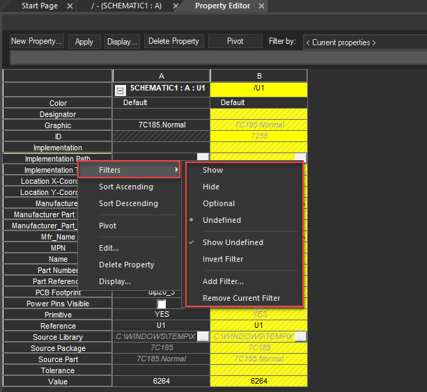
Property Edit menu options
Show
The selected column will always appear when you use this filter, unless the filter is inverted.
Hide
The selected column will never appear when you use this filter, unless the filter is inverted.
Optional
The selected column will only appear if the property exists on one or more objects when you use this filter.
Undefined
The selected property is not defined. It is neither included in nor excluded from the filter.
You can control the display of undefined properties on individual tabs of the property editor with the next two choices on the Filters menu. Select any combination of the two.
Show Undefined
Specifies that any undefined property columns that are selected will appear when you use this filter. However, if you also select Invert Filter, these same selections will not appear.
Defined properties appear at the beginning of the spreadsheet (toward the left side) when you select Show Undefined.
Invert Filter
Specifies to show hidden property columns when you use this filter. Conversely, it will hide any property columns that you have specified to show. For example, if a property is optional and does not exist on any objects, you can use Invert Filter to show the property.
The last two menu choices affect all tabs on the property editor.
Add Filter
Specifies to add a new filter to all tabs. The default of a new filter is to show all properties as undefined.
Remove Current Filter
Specifies to delete the filter that displays in the Filter by list box from the list. You cannot undo this operation. Your results will be more reliable if you use the Filters menu to make changes rather than editing the PREFPROP.TXT file manually. Changes to the filters are saved to PREFPROP.TXT when you close the spreadsheet. If you need to retrieve the original version, you can copy PREFPROP.TXT from the installation CD in the Capture directory. You can use the default filters to narrow the scope of properties it displays. Because you can have hundreds of properties assigned to your parts, nets, pins, and title blocks, it is more efficient to view only the properties you want to see. Capture provides a template that defines the properties that appear if you are targeting your design for PSpice or a board layout tool.
Filtering Properties
You can narrow the scope of properties that are displayed by applying the default filters or by creating new filters, and then applying them.
Filtering Properties Using Default Filters
To filter a property using the filters available by default, do the following:
- In the schematic page, choose the Edit – Select All menu command.
- Right-click and choose Edit Properties.
The Property Editor window appears. - Select the Parts tab at the bottom of the window to display all the properties of the parts you selected.
- Click the Filter by list down arrow to expand the list of filters, then select a filter.
Depending on your selection, the displayed properties change to include those properties you can apply to the parts.
For example, you can select PCB Editor to include the properties you might want to apply to the parts for use in a PCB netlist. - Enter a value into one of the cells and click Apply.
The property and new values apply to the selected part.
Creating a New Filter
To create a new filter, do the following:
- Right-click any column heading in the spreadsheet, point to Filters, and choose Add Filter.
- Type the new filter name in the Add Filter dialog box.
- Click OK.
The new filter will be saved inPREFPROP.TXTwhen you close the property editor.
Editing a Filter
To edit a filter, do the following:
- Click the Filter by list down arrow to expand the list.
- Select a filter.
The appearance of the properties on the spreadsheet may change when you change the filter. - Right-click any column header and point to the Filters menu.
- Change the property definitions and appearance on the spreadsheet as required.
Editing Properties
All objects in Capture have attributes, or properties. Examples include the type of object (such as text, wire, or title block), part reference, color, font, and visibility. Some properties, called inherent properties, are essential to Capture—you cannot remove these inherent properties, though you can change the values of some of them. Other properties, called user-defined properties, may be used by external tools—they are not used by Capture, so you can add and modify these user-defined properties to suit your needs.
Except for occurrence properties, the schematics of externally-referenced libraries and designs must not be edited. You can view them as read-only designs. Any attempt to edit and save these designs from within your schematic can introduce errors, such as duplicate reference designators and other problems.
When saving schematics with externally-referenced libraries or designs, occurrence properties are saved but altered instance values are not. If you want to change externally-referenced libraries or designs, you need to first close the referencing design. Then, open the referenced library or design, make the necessary changes, and save and close the referenced library or design. At this point, you can reopen the original design and reference the modified design.
To edit properties associated with a part, a wire, or a pin, do the following:
In the schematic page editor:
- Select the object.
- Choose the Edit – Properties menu command.
The Property Editor window appears.
Exporting Part and Pin Properties
You export the part and pin properties in a design to a property file (.EXP). The property file can be edited in any application of your choice and then imported. It is recommended to update (annotate) part references before you export properties. You can change part references by editing the References column of the property file.
To export part properties or part and pin properties, do the following:
- Open the project with the design or library holding the parts.
- For a design, select the schematic folders or schematic pages containing the part you want to export.
OR
For a library, select the parts to export. - Choose the Tools – Export Properties menu command.
The Export Properties dialog box appears.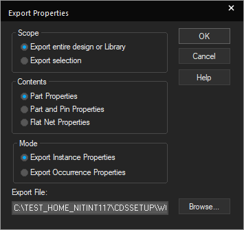 -- For a design, you can export all the parts or just the parts in selected schematic folders and schematic pages. You cannot select parts in the design cache or library cache for export.
-- Pin-numbers are stored for each device/section of the part
-- For a library, you can export all parts or just selected parts, but you cannot export part aliases. If you export and edit properties of a part that has aliases, the aliases reflect the changes. - In the dialog box, specify whether the property file is to include the entire design or a selected portion, whether you want to export properties for pins as well as parts or flat nets, and whether you want to export instance or occurrence properties.
Before you click OK in the dialog box, note the location of the export file in the Export File text box. -
Click OK to create the property file.
The property file is created and opened in the default editor in a separate tab.
For projects, Capture reports a part once for each place it is used in the design. One HEADER line applies to the entire project: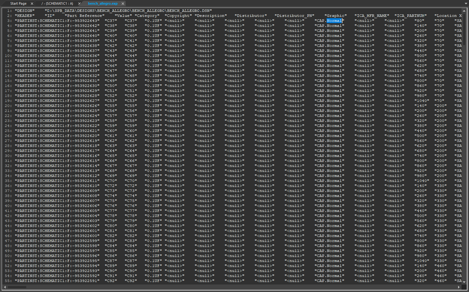 The Export Properties command stores the device information for the part. If a homogeneous part has 2 sections, the information corresponding to both the sections is stored. These sections can be recognized in the
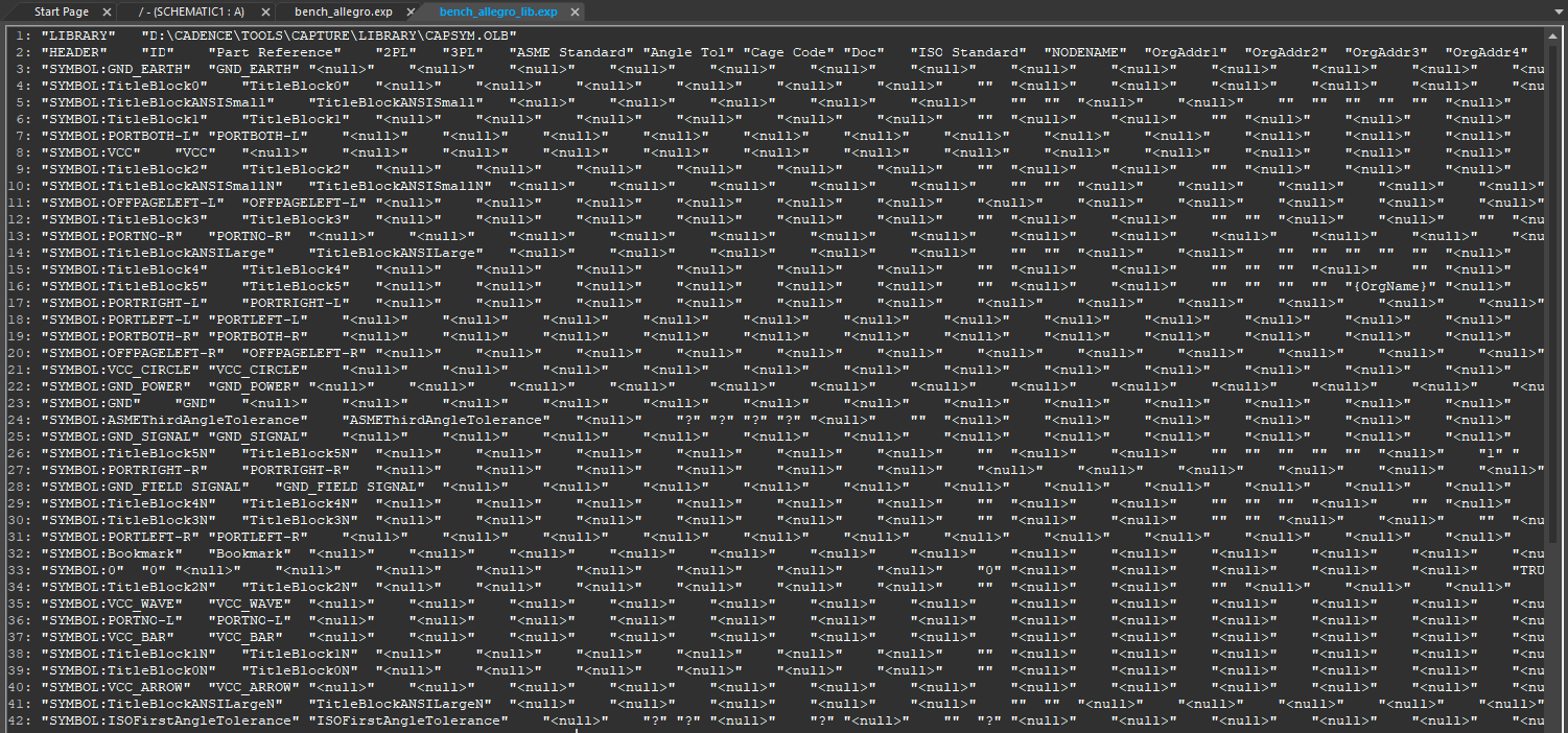
 EXPfile through designator prefix.For libraries, Capture reports each part in the library :
The following table illustrates what happens when a part or pin has a property or does not have a property for the different states of the field:
|
State |
Part or pin has the property |
Part or pin does not have the property |
|
Field is not <null> |
Property value changes to specified value. |
Property is added with specified value. |
|
Field is <null> |
Removes existing property. |
Object is not affected. |
|
Field is empty |
Capture shows {Property Name} as place holder (when the property is visible). |
Capture shows {Property Name} as place holder when the property as visible). |
Editing Property File
When you export properties, Capture creates a tab-delimited list of keywords, identifiers, and properties, each of which is enclosed in double quotation marks. You can edit this file in a spreadsheet or database program, or even in a text editor (as long as the editor does not convert the tabs to spaces). Depending on which tool you use, you may see the property file as rows and columns of cells or fields or as lines of text.
To edit a property file, do the following:
- Right-click the property file name in the Outputs node and choose Edit.
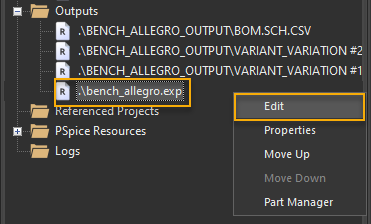 The file opens in a separate tab.
 You can also edit this file in a spreadsheet or text editor.
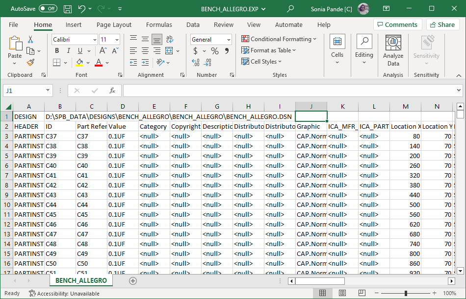
- Add a field to a HEADER line and subsequent lines to add a column.
This adds a property and pins with a value in this field. The name of the property is the string in the HEADER line. The value assigned to the part or pin is the string in the corresponding field. If the corresponding field is empty, Capture adds a property with no value and displays the property name as a placeholder. - Change a property value to
<null>.
This deletes any existing property. - Delete a field from a HEADER line and subsequent lines to delete a column.
This has no effect on any part or pin. Deleting extra columns for properties you do not want to change may make the property file easier to edit. If you delete a field from a HEADER line without also deleting the corresponding fields from subsequent lines, an error is reported and changes are not processed when you import the property. - Change the value of a field.
Resets the value of the property on the object to which it refers.
Making certain changes to the property file causes the column headers and fields to be out of sync and invalidate your design. You must not:
- Change or delete the first line.
- Delete the first field in any line.
- Delete a field from a HEADER line without also deleting the corresponding fields from subsequent lines.
- Make changes in the ID, Net Name, and Net ID fields in the property file (
*.exp). The changes will not reflect in your design when you use the Import Properties command.
Importing Part and Pin Properties
You can update the pin-type, pin-numbers and user-defined pin properties of the parts in a design by importing properties. To support various popular spreadsheet and database applications, properties can be imported with or without enclosing quotation marks around each field in the property file. The fields must be tab-delimited, though—all the other characters, including commas and leading and trailing spaces, are treated as part of a field's text. Ensure that your spreadsheet or database program can save in this format.
Capture does not import all the part and pin properties. So if a property is exported using the Export Properties command, it does not imply that you can change its value and then import the change back into the part or pin. The thumb rule is that any property that is editable in the Property Editor in Capture and is exported can be imported. For example, the pin type property of a pin is exported by the Export command. However, if you edit the value in the export file and import the file back into Capture, the pin type does not change.
To import part properties or part and pin properties, do the following:
- Open the project with the design or library holding the parts.
- Choose the Tools – Import Properties menu command.
The Import Properties dialog box appears. - Select the property file (
.EXP). If the property file is not listed, do one or more of the following:- In the Look in drop-down list, select a new drive, a new directory, or both.
- In the Files of type text box, select the type of file you want to open.
- Click OK to apply the properties.
When you import the edited properties, Capture expects to find the schematic pages and parts unchanged. After you export properties, do not edit the project or library from which the properties were exported until after you import the changed properties. If you do, the Import Properties command will fail, and you will have to export and edit the properties again.
Finding and Replacing Properties
You can find and replace property characteristics, such as property values, and display properties using the Replace dialog box. You can find objects by parts, pins, nets, text, class, with additional search criteria for object properties and it's associated display properties. To find and replace properties in Capture, perform the following steps:
- Choose Edit – Replace.
Alternatively, use the shortcut,
CTRL+H.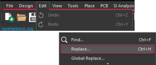
The Replace dialog box appears.
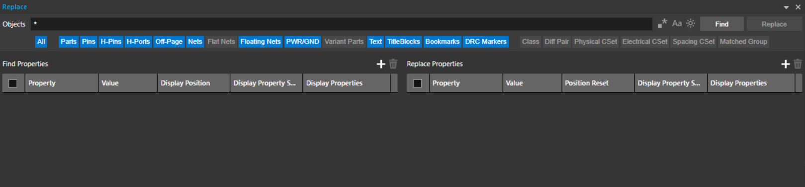
-
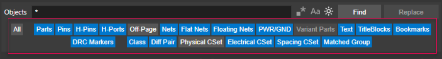
In the Objects search box field, enter the property value string for the part you are searching for. The asterisk "*" is used with a truncated search, which is there by default.
Alternatively, you can further narrow your search by selecting or deselecting the object type to which you want to apply the search. You can filter multiple object types.
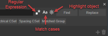
- Select the following icons on the header, as required:
- Use regular expressions in your search string.
- Set the match cases option for your search string.
- Highlight the object found from the search.
This search is applied to the object criteria only, and not on the advanced criteria.
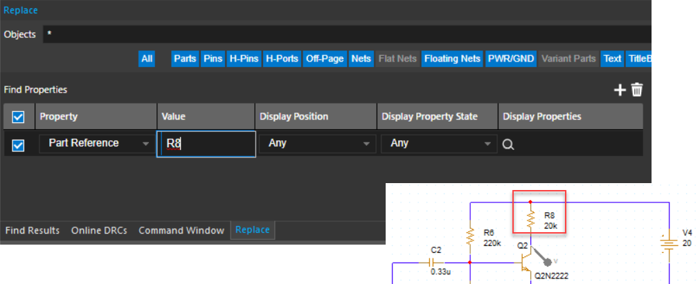
Finding Objects with Defined Properties
To find properties of a part, perform the following steps:
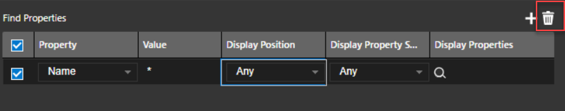
- In the Find Properties section, click
 to add a property row that defines a criteria for populating the find results.
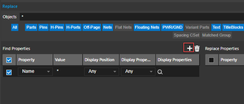
You need to add the following details:
- Property: Select the name of the property from the drop-down menu. The newly added property gets updated in drop down when we select the design and do
CTRL+H. - Value: Specify a value of the selected property. Wildcard characters are not supported.
- Display Position: Select the position of the property how you want it on the schematic. The value of Display Position can be default or non-default in case property has been moved from the default location. Any ignores default or non-default.
- Display Property State: Specify how properties are shown on the schematic. The value of Display Property State is default, non-default or any, where default refers to the state of the properties in the library.
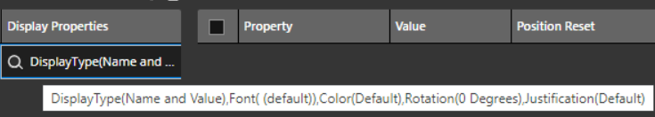
- Display Properties: Defines how the selected criteria are shown on the schematic. For example, it specifies the font, color, and other property display settings on the schematic.
- You can delete the find criteria in the following ways:
- Right-click the find criteria and click Delete.
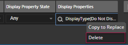
- You can simply click the delete icon at the top-right corner of the Find window. It deletes all the checked criteria.
- You can select multiple checkbox and click the delete icon.
- Right-click the find criteria and click Delete.
- Click Find to find the objects that meet the selected criteria.
 The results are displayed in the Find Results window as shown:
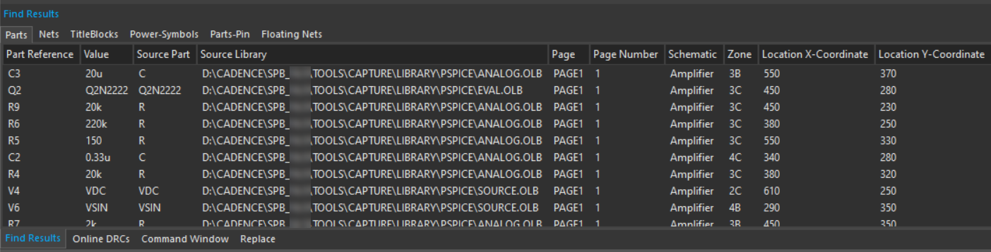
Find Similar
This allows to auto-feed the display properties of an object in the Find window based on your criteria. The object shows all display properties of your desired font. You can apply it to the entire design.
Editing the Configuration File
You can edit the configuration file that defines the default properties to be used for Find Similar objects. To update the default findsimilarprops.cfg file,
- Select Edit and define the path to the file under the Configuration Files in Extended Preferences.
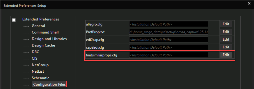
- Restart the Capture application to see the changes.
The name property of an off-page connector can have a unique display position and display attribute, but during an advanced search, only the Name property values are considered, while the display properties and attributes are ignored.
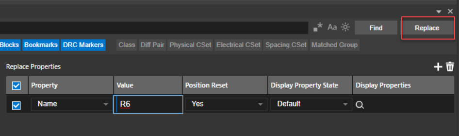
Replacing Property Characteristics
To replace values, position, state and other characteristics of part properties, perform the following steps:
- In the Replace Properties section, click to add a property row that defines a criteria for populating the replace results.
 Or, right-click any property column in the Find Properties section and select the Copy to Replace button.
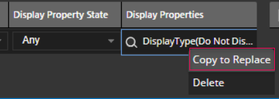
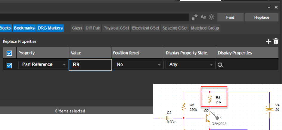
- Specify the property name or value that you want to replace.
- Click Replace to replace the property objects such as its value, position or the property state.
 You can replace multiple properties in one go.
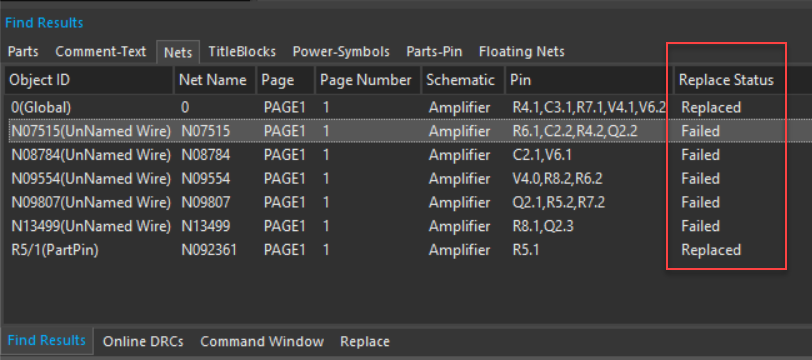
Performing Inline Replace
When you click Replace button to replace the object property attributes based on the selected criteria, the Find Results window is displayed that shows the status of the replaced objects by their IDs, net names, page number, pins and other columns. The Replace Status can be Replaced, Failed, Partially Replaced, or Not Applicable.
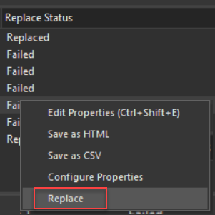
To replace a specific object inline, do the following:
- Select an object in the Find Results window.
- Right-click and click Replace.
 The Replace button is activated only once and gets disabled automatically when replace is already done.
View the next document: 10 – Managing Projects
If you have any questions or comments about the OrCAD X platform, click on the link below.
Contact Us