10 – Managing Projects
Archiving a Project
You can save the project (.OPJ) and all the related files (design, library, output files, and referenced projects) in a different directory and also create a zip file of this directory for archival purposes. You can also specify any additional files or directories that you may want to be archived along with your project files. For example, you can archive external designs, global PSpice model libraries, and global include files along with your PSpice project or data sheets for the parts.
To archive a project, do the following:
- Ensure that the project to be archived is active and the schematic pages for the project are not open.
- Choose the File – Archive Project menu command.
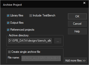
The Archive Project dialog box displays. In this dialog box, you can save all the files related to your project in the directory you specify for archival, and compress the directory into a single zip file with a.zipextension. You can use the WinZip software to extract the zip archives created using Capture. -
Select the files you want to be archived with your project. If you do not select any of the options (Library files, Output files, or Referenced projects), Capture by default archives only your project (
.OPJ) and design (.DSN) files.For PSpice projects, the simulation profiles and local files (.LIB,.STL,.INC) will all be archived along with the project. The Output files option also archives simulation output files such as.DATand.OUTfor PSpice projects. The archiving methodology for PSpice model libraries is as follows:
- The files with the
.als,.drt,.log,.prp,.aapextensions, and the profile name files are archived under the following directories:- <design_name>-PSpiceFiles/<Schematic_name>/*.als
- <design_name>-PSpiceFiles/<Schematic_name>/*.drt
- <design_name>-PSpiceFiles/<Schematic_name>/*.log
- <design_name>-PSpiceFiles/<Schematic_name>/*.prp
- <design_name>-PSpiceFiles/<Schematic_name>/*.aap
- <design_name>-PSpiceFiles/<Schematic_name>/<profile_name>/*.*
- Profile-level model libraries are archived under their respective profiles and referenced as
.\<library_name>.lib.
For example, when a profile; AC containing a model library diode.lib is archived, the diode.lib is copied under the directory AC and the simulation settings is modified as:.\diode.lib. - Design-level model libraries are archived under
.\<design_name-pspicefiles>\<design_name>\<library_name>.lib.
For example, when a design called histo containing a model library bipolar.lib is archived, the model library bipolar.lib is copied under directoryhisto-pspicefiles\histoand the simulation settings is modified as:.\histo-pspicefiles\histo\bipolar.lib. - In case of global-level model libraries:
- a copy of model library is created under the existing
_<design_name>.lib (_if exists). - a new
<design_name>.libfile is created and a copy of model library is added to the<design_name>liband the simulation setting is modified as design-level library.
- a copy of model library is created under the existing
- The files with the
-
Click the ...button in the Archive directory text box to select the directory to be archived.
-
Find and select the directory in which you want your project archived and click OK. If required, create the directory.
-
Click OK.
You can also enter the relative path of the archive directory in the Archive directory text box. This path is treated as relative to the project being archived.
-
Click OK in the Archive Project dialog box.
Capture archives your project with all the selected files to the specified directory and displays information/errors in the Session Log.
To create a zip archive for the project, do the following:
- Ensure that the project you want to archive is active and the schematic pages for the project are not open.
- From the File menu, choose Archive Project.
The Archive Project dialog box appears. - Set the directory to which you want to save all project files.
- Select the Create single archive file check box to activate the File name text box.
-
Specify a file name for the zip archive file in the File name text box.

The default file name for the zip archive file is <projectname-current date>. The file extension (.zip) is automatically added to the zip archive file.
- Click OK.
Capture zips all the files in the specified directory and generates a zip file with.zipextension. The Session Log displays all the events that occur during the archiving process and report whether the process completed successfully or with errors.
- The working directory does not change to the newly set archive directory.
- You can extract the zip archive using the WinZip software.
- Archiving to a single file with a .zip extension does not compress the contents.
To add additional files and directories to the archive, do the following:
- Ensure that the project you want to archive is active and the schematic pages for the project are not open.
- Choose File – Archive Project.
- Set the directory to which you want to save all project files as described in To archive a project section.
-
Click the Add more files >> button.
The Archive Project dialog box expands and displays a grid where you can add more files and directories.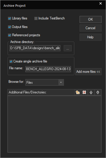
Click the Add more files << button to revert the Archive Project dialog box to its default state.
- Select an option from the Browse for list box. Select the Directories option to add directories or the Files option to add more files to your archive. The Files options is the default selection.
- Click the New(Insert) button or press the Insert keyboard key. An edit box with a blinking cursor appears in the Additional Files/Directories list.
- Click the ... button to locate the files or directories you want to add in the archive.
A file or directory selection dialog box appears depending on your selection in the Browse for list box. For example, if you selected the Directories option, then the Select Directory dialog box appears. Otherwise, the Select File (s) dialog box appears. - Find and select the file or directory to be added to your archive. The location path of the selected file or directory is added in the Additional Files/Directories list.
– Do not enter relative path for files or directories in the Additional Files/Directories list.
– You can use the standardCTRLorSHIFTkeys to select multiple files in the Select File (s) dialog box.
– You can also select multiple files by dragging the left mouse button over the files you want to select in the Select File (s) dialog box.
– The Additional Files/Directories list displays information based on your selection in the Browse for list box, that is, if your selection is Directories then only the directories added to the list are displayed and vice-versa.
– Use the button or press the
 Deletekey to delete the files or directories you do not want in the Additional Files/Directories list.
– The archiving mechanism ensures that duplicate files or directories do not get added to the Additional Files/Directories list. - Click OK in the Archive Project dialog box. Capture archives your project with all the selected additional files and directories to the specified directory.
- The files and directories you add using the Additional Files/Directories list are added to the archive directory under a separate sub-directory called Additional files.
- The archived project (
.OPJ) file does not contain references to the additional files and directories added using the Additional Files/Directories list. - The settings you specify in the Archive Project dialog box are saved in the
CAPTURE.INIfile. The settings are used whenever you start the next archive session except for the files and directories list in the Additional Files/Directories list.
Auto Recovery of Files
The auto recovery feature of Capture is designed to protect you from losing work as a result of a system crash or power outage. Capture automatically saves the state of the open design and library files at the end of each interval set in the Miscellaneous tab of the Preferences dialog box. Capture removes auto-saved files from your system when a project is closed and when you exit Capture normally. The Preferences dialog box appears when you choose Tools – Preferences.
Auto recovery is not an automatic saving feature intended to replace the Save commands. If you intentionally exit Capture without first saving your changes, all the changes are lost. Auto recovered files are automatically deleted when you exit Capture normally.
Auto-Saving of Files
Capture maintains a file called FILES.ASL in the %TEMP%\AUTOSAVE directory that has a list of all the design and library files that are opened. Capture updates FILES.ASL when a project is opened or closed. If your system shuts down unexpectedly without exiting Capture, FILES.ASL has a list of design and library files that were open for editing when the system failure occurred.
Auto recovery works on a timer that you can set to specify how often (if at all) you want Capture to auto-save the currently open and modified design and library files.
The frequency can be from five minutes to every 120 minutes (2 hours).
When the Interval is reached, the following sequence of events takes place:
- Capture examines all open design and library files.
- If a file that is part of the project is open for editing, Capture examines it to see if it has been modified since the last auto-save.
- If it has, it is saved to the
%TEMP%\AUTOSAVEdirectory. - If the project itself has been modified, or one of its files was auto-saved, the project itself is saved to the
%TEMP%\AUTOSAVEdirectory. - When this happens, the auto recovered version of the project file is updated such that the path of any auto-saved designs or libraries changes to point to the
%TEMP%\AUTOSAVEdirectory. - Any paths of ".\" are changed to point to the directory the project was loaded from.
- Capture can then open the project from the
%TEMP%\AUTOSAVEdirectory with all paths pointing to the correct location: the%TEMP%\AUTOSAVEdirectory for those files that were auto-saved, and the original location for those files that were not modified and therefore not auto-saved.
When a project is closed normally, all auto recovered files in the \WINDOWS\TEMP directory for that project are deleted.
Restoration of Auto-Saved Files
Auto-saved files are recovered in the following sequence:
- When you start Capture, it checks for
FILES.ASL. - If the file is found, Capture reads it.
- If the Capture session closed unexpectedly the last time it was used, and there are design and library files listed in
FILES.ASL, the design and library files are opened from their original locations - Capture then appends the string,
(Restored), to the project manager's title to indicate that the project was loaded as a result of a previous system failure. - Capture also looks for design and library files that were auto recovered to the
%TEMP%\AUTOSAVEdirectory. - If any file is present:
- Capture opens it.
- Changes its name to a default name such as
PROJECT1. - Adds the string,
(Restored), to the project manager's title. - Removes the file name and directory from the project manager window.
- Marks the project as modified.
- Capture then looks in the project for any files that reference the
%TEMP%\AUTOSAVEdirectory. - Any files that do are auto recovered to the
%TEMP%\AUTOSAVEdirectory, are opened, their filenames and directories are removed from their project manager windows, and they are marked as modified.
Adding and Deleting Project Files
Adding files to a Project
Typically, the files you add to your project will be files that have specific functions in the design process. For example, you might add a standard delay file to provide timing information for simulation with NC VHDL or some other simulation tool. However, you can add any files you want to a project, including documentation files (perhaps a functional specification) or waveform files (to show the results of a simulation).
To add a file to the project, do the following:
- In project manager, select the folder to which you want to add a file.
- Choose Edit – Project.
The Add File to Project Folder - <folder_name> dialog box displays. - Select the file you want to add and click the Open button.
The file is added to the project.
Alternatively, drag-and-drop the file from the File Explorer into the folder in the project manager.
Deleting Files from a Project
You can delete files from your project just as you delete files in File Explorer.
To delete a file from the project, do the following:
- In project manager, select the file to be deleted.
- Press the
delete/Delkey.
The file is removed from the project.
- You cannot delete schematic pages or schematic folders if those schematic pages (or schematic pages within those folders) are currently open in Capture. You must first close the schematic pages in question.
- Deleting schematic folders, schematic pages, parts and symbols is permanent. You cannot use the Undo command to retrieve deleted items from the project manager.
Undoing and Repeating Commands
You can reverse an action you performed on design by using the Undo command If you want to repeat the action you reversed, you can use the Redo command. Undo and Redo functionality is available in the schematic editor, the part editor, and the property spreadsheet. The Redo command can be used only after an Undo command.
You can use Undo/Redo for:
- Object creation/deletion activities (for example, Cut, Copy, Paste, and Place commands).
- Object manipulation (for example, Move, Resize, Rotate, and Mirror commands)
- Property value modifications.
Multiple undo/redo operations
You can undo/redo commands:
- Sequentially, exactly one command at a time.
- By setting label states. Label state enables you to tag the schematic at different stages of design. You can later use these tags to go to a particular stage of the design and then undo/redo a number of steps that were performed at that point in the design.
For example, you performed the following actions on a schematic page:
- Place a part.
- Label the schematic as stage1.
- Rotate the part by 90 degrees.
- Wire one of the pins on the part to another part on the schematic page.
- Place another part.
- Label the schematic as stage2.
You can use the Undo (CTRL + z)command repeatedly to return the schematic page to its state at any point in this sequence. After step 5, you might decide to rotate the part by 270 degrees instead of 90 degrees and change the wire-pin connections as well. In such a case, instead of undoing a number of steps, you can jump to the label state stage1. This takes you to the state of the schematic described in step 1. You can then modify the design as required.
Using Undo/Redo for Designs and Schematic Pages
A separate cache of undo/redo data is maintained by Capture for each schematic page. You can use the Undo/Redo operations independently for each schematic page in your design.
In complex hierarchical designs, there can be more than one occurrence of a particular schematic. When editing in this environment, objects and annotations are handled by separate mechanisms.
For objects, the edits are reflected in all the pages open on different occurrences of that page. If there are two pages open on two different uses of a schematic and you move an occurrence on one page, the occurrence will also move in the second page. When the user performs an UNDO, the state of the objects is restored on all occurrence pages identically.
For annotations edits are reflected uniquely in the occurrence pages. The annotation displayed by a view is selected by filter. UNDO in this case will restore the annotation value only on the particular occurrence page
For example consider the case of a reused instance with two occurrences H1/U1 and H2/U1. This instance has different annotations for these two occurrences. When the page is open on H1/U1, the Reference Designator displays as U25; when the page is open on H2/U1, the Reference Designator displays as U72.The behavior of UNDO will be as shown in following sequence:
|
Command |
Undo/redo |
Schematic state |
|
Open root schematic |
disabled |
Schematic displayed |
|
Open occurrences H1/U1 and H2/U1 |
disabled |
Occurrence pages displayed |
|
Move a component in H1/U1 |
Undo Move |
Component moved on both H1/U1 and H2/U1 |
|
Change reference designator on H1/U1 to from U25 to U50 |
Undo Text |
H1/U1 (only) is changed. |
|
Change reference designator on H2/U1 from U72 to U80 |
Undo Text |
H2/U1 (only) is changed. |
|
Undo |
Undo Text |
H2/U1 reference designator returned to U72 from U80. |
|
Undo |
Undo Move |
H1/U1 reference designator returned to U25 from U50. |
|
Undo |
disabled |
Component moved to its previous position on both H1/U1 and H2/U1. |
Clearing the Undo/Redo cache
There are a number of operations that will clear the undo/redo cache (that is, these operations cannot be undone, nor can the schematic page be returned to a state that existed previous to the execution of these operations):
- Choosing Update Current or Update all after editing a part on a schematic page
- Replace Cache, Cleanup Cache, or Update Cache
- Edit Properties through the Browse/Find commands or through third-party tools
- Annotation, back-annotation, Update properties, Import Properties, or Cross Reference operations
To undo an action
- From the Edit menu, choose the Undo command.
Shortcut
Toolbar: 
To undo an Undo command
- From the Edit menu, choose the Redo command.
Shortcut
Toolbar: 
Graphical Operation (GOp) Locking
A schematic page often contains a large number of different types of objects like parts, pins, buses, wires. A user often needs to perform operations like adding new objects, changing object properties, moving, creating and deleting objects. All these operations require extensive user interaction with the Capture interface. Also, with the increasing complexity of designs, the number of objects on a page and pages in a design has increased exponentially. All these issues raise the need in Capture for providing a methodology to lock the state of a design at a particular point of the design process. For example, a designer should have the ability to maybe lock the layout of a schematic page.
To address such issues, Capture includes a graphical operation locking (GOp) feature that allows you to lock objects (like components, pages, folders and even design) in a Capture project.
When you graphically lock an object, the graphical aspects of the object are locked. This implies that non-graphical aspects of an object such as its properties are still editable. For example, if you lock a part on a schematic page, you cannot delete, or move the part but you can change, say, the PCB footprint of the part.
GOp locking lets you lock any object in a Capture design. You can lock the design, the schematic folders within the design, the pages within the schematic folders, and the objects on the schematic pages.
The features of various locked objects are explained in the following subtopics:
- Features of a Locked Schematic Page Object
- Features of a Locked Schematic Page
- Features of a Locked Schematic Folder
- Features of a Locked Design
- Cascading and Roll-up Effects of Locking
Features of a Locked Schematic Page Object
- The object cannot be deleted or cut.
- The object cannot be moved to another part of the page (using a cut-and-paste operation or a mouse drag operation).
- The object cannot be moved to another page (using a cut-and-paste operation or a mouse drag-and-drop operation).
- The object can be copied to another page or as another instance on the current page. However, the copied instance of the object is locked as soon as you paste it on the page.
- If the locked object is a part, the part editor for the object is inaccessible. This means that the menu option to open the part editor for a locked part is unavailable.
- The replace or update cache operations will fail if they effect a locked part. Say a design contains multiple instances of a part where some instances are locked and some are unlocked. In this case, the replace or update cache operations on a part with multiple instances will fail if these operations effect the locked instances. This means that these operations will not update even on the unlocked part instances.
- The Update All operation on an unlocked part instance (executed in the edit part procedure) will fail if this operation effects a locked part instance. This means that this operation will not effect even on the unlocked part instances.
Since, this type of locking is graphical so you are still permitted to edit the properties of a locked part. This implies that you can open the property editor for a locked object and add, modify or delete properties on the part.
Features of a Locked Schematic Page
- The page cannot be deleted or cut.
- The page cannot be moved to another schematic folder (using a cut-and-paste operation or a mouse drag-and-drop operation).
- The page cannot be renamed.
- Schematic page objects cannot be added to the page. This implies that an object cannot be placed on a locked page using the Place command. Also, an object cannot be placed on a locked page by copying the object from another page and pasted it onto the locked page.
- The page can be copied to another folder. However, the copied page is locked as soon as you paste it to the destination folder.
- All the page objects are locked as soon as the page is locked. Also, objects on a locked page may be explicitly unlocked. For details on the cascading and roll-up effects of locking pages see the section Cascading and roll-up effects of Locking.
Features of a Locked Schematic Folder
- The folder cannot be deleted or cut.
- The folder cannot be moved to another design (using a cut-and-paste operation or a mouse drag-and-drop operation).
- The folder cannot be renamed.
- Schematic pages cannot be added to the folder.
- The make root property of a locked schematic folder cannot be modified.
- The folder can be copied to another design. However, the copied design is locked as soon as you paste it to the destination design.
- All the pages are locked as soon as the folder is locked. Also, pages in a locked folder may be explicitly unlocked. For details on the cascading and roll-up effects of locking folders see the section Cascading and roll-up effects of Locking.
Features of a Locked Design
- Schematic folders cannot be added to the design.
- All the folders are locked as soon as the design is locked. Also, folders in a locked design may be explicitly unlocked. For details on the cascading and roll-up effects of locking designs see the section Cascading and roll-up effects of Locking.
-
Design operations, netlisting, annotations, DRC and permitted on a locked design. You can also simulate a locked design.
If you run these commands on a locked design, and this causes a graphical change in the design, Capture lets you change but it will immediately be locked onto the design.For example, you run the DRC on a locked design (or the DRC affects locked objects in the design). If the design has any DRC errors or warnings, Capture places the markers even on locked object of the design. However, if a marker is placed on a locked page, the marker is immediately locked. You need to either unlock the page or the marker to remove the marker.
Cascading and Roll-up Effects of Locking
When you lock a container object, such as a page, a folder, or a design, all the objects within the container are also locked. Also, this process cascades down to the lowest-level object.
So, if you lock a page, all the objects on the page are locked. If you lock a folder, all the pages contained in the folder are locked. In addition, the objects on each of the pages are locked.
When you lock a container object, you can unlock specific objects within the locked container by explicitly unlocking them. However, since locking and unlocking does not cause a roll-up effect, the unlock operation does not unlock the object container.
When you lock a container object, a lock symbol appears over the container icon in the Project manager. Now, if you explicitly unlock one or more objects within the locked container, the lock symbol remains but it changes to an open lock. This indicates that the container is locked but one or more objects within the container are unlocked.
The locking operation on an object within a container is specific to the object. This implies that the lock or unlock operation on an object overrides the operation on the object container.
Locking and Unlocking Objects
You can lock (and subsequently unlock) any object in a Capture project. You can lock the objects on a schematic page, the pages in a schematic folder, the folders in a design, and the design in a project.
Locking an Object
To lock an object in Capture, do the following:
-
Select the object to lock:
-
For schematic page objects, use the multi-select feature on the schematic page to select and lock multiple objects simultaneously.
-
For project manager objects, such as pages, folders and designs, select the objects in project manager. However, you cannot lock multiple Project manager objects simultaneously.
-
- Choose the Edit – Lock menu command.
Alternatively, right-click the object (on the page or in the Project manager) and choose Lock.
When you lock a schematic page object, the look-and-feel of the object when it is selected is changed. When you lock a project manager object, a lock symbol appears over the icon of the object in the Project manager.
- After locking (or unlocking) one or more objects on a design, the locked state of the objects must be saved. For example, say you lock one or more objects on a schematic page. After locking the objects, if you close the page without saving changes, the locked state of these objects is lost.
- If you lock one or more objects in a design, export the design and then again import the design, all the locks on the imported design are lost.
Unlocking an Object
To unlock an object in Capture, do the following:
- Select the object to unlock.
-
For schematic page objects, use the multi-select feature on the schematic page to select and unlock multiple objects simultaneously.
-
For project manager objects, such as pages, folders and designs, select the objects in project manager. However, you cannot unlock multiple Project manager objects simultaneously.
-
- Choose the Edit – UnLock menu command.
Alternatively, right-click the object (on the page or in the Project manager) and choose UnLock.
Example
Consider the example of a folder, SCHEMATIC1, containing two pages, PAGE1 and PAGE2.
- Lock PAGE2.
- Lock SCHEMATIC1.
As locking is a cascading operation, locking SCHEMATIC1 affects the lock status of its pages. In this case, PAGE2 is assigned locked state, so the cascading operation affects only PAGE1.
The lock operation does not affect PAGE2, not because the page was already locked but because the locked state of an object overrides the locked state of the container. - Unlock SCHEMATIC1.
Again, due to the cascading effect of unlocking, the pages within SCHEMATIC1 are unlocked.
However, since PAGE2 was locked specifically and not as part of the cascading lock on SCHEMATIC1, the cascading lock operation does not affect the locked state of PAGE1.
View the next document: 11 – Establishing Connectivity
If you have any questions or comments about the OrCAD X platform, click on the link below.
Contact Us