07 - Working with Schematic Pages
Creating a Schematic Page
When you create a project in Capture, a design is created immediately. The root schematic folders are created within the design and one schematic page is created within the folder. You can also create multiple schematic pages within a schematic folder.
To create a schematic page, do the following:
- On the File tab of the project manager, select the schematic folder to which you want to add the new schematic page.
- Choose Design – New Schematic Page.
Alternatively, right-click the folder to which you want to add the new schematic page and choose New Page. - Specify a name for the new schematic page and click OK.
Defining Schematic Page Characteristics
Using the design template, you can establish the characteristics of a schematic page for an entire project. You can also override these defaults and establish characteristics of a specific schematic page using the Schematic Page Properties or Design Properties command.
Capture creates a schematic page size to suit your printer or plotter. You can choose from the five standard page sizes or specify a custom size. The default title block symbol, default title block information, border, and grid references can all be established for each project. Title block visibility can be specified for the entire project or for each schematic page.
To define grid references for new designs and schematic pages, do the following:
-
Choose Options – Design Template, and then choose the Grid Reference tab.
- Make selections for the horizontal and vertical grid references and click OK to close the Design Template dialog box.
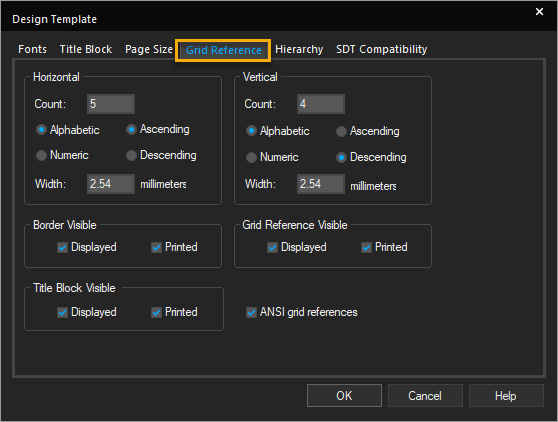
Until you change theGrid Reference tab, any designs or schematic pages you create reflect these selections.
To change the grid references for an existing page, do the following:
- Open the schematic page editor for the schematic page.
- Choose Options – Schematic Page Properties, and then choose the Grid Reference tab.
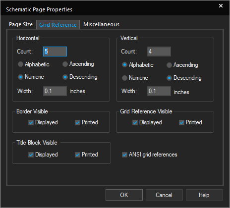
- Make selections for the horizontal and vertical grid references and then click OK to close the Schematic Page Properties dialog box.
The selections are reflected in the active schematic page.
To define schematic page size for new designs and schematic pages, do the following:
- Choose Options – Design Template, and then choose the Page Size tab.
- Select Inches or Millimeters as the unit of measure.
- Select a page size.
-- If you choose inches, the choices are A, B, C, D, E, and Custom.\
-- If you choose millimeters, the choices are A4, A3, A2, A1, A0, and Custom. - Specify a value for pin-to-pin spacing, and click OK to close the Design Template dialog box.
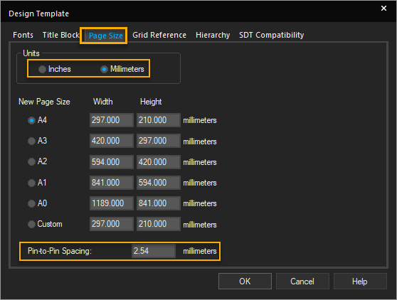
Until you change the Page Size tab, any designs or schematic pages you create will reflect these selections.
Schematic Page Editor and Part Editor
OrCAD X Capture includes a number of editors, including a text editor with features for creating VHDL models, a schematic editor, and a part editor. These editors mostly function in accordance with the general standards that one might expect in a Windows-based tool. However, there are certain unique traits (particularly with regard to zooming and scrolling) that distinguish the Capture editors from other Windows editors.
Schematic Page Editor |
|---|
|
|
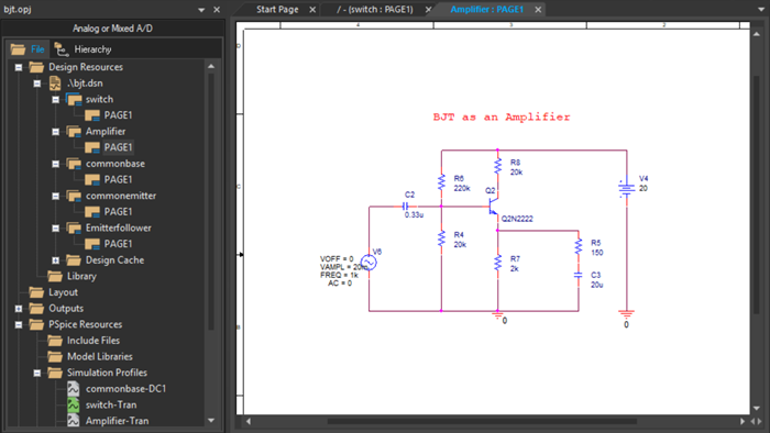
| You edit schematic pages in the schematic page editor window. This window has two view splitters. The splitter at the upper right divides the view horizontally. The splitter at the lower left divides the view vertically. Each view has its own scroll bars, so you can view separate areas on the same page. |
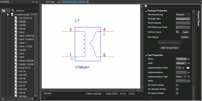
Part Editor |
|---|
|
|
| You edit parts and symbols in the part editor window. This window has two view splitters. The splitter at the upper right divides the view horizontally. The splitter at the lower left divides the view vertically. Each view has its own scroll bars, so you can view separate areas on the same part. |
Moving Around in the Editors
When working on a schematic page, some operations help you move around the schematic easily, such as scrolling, panning, zooming in and out, moving to a specific location, reference or bookmark, or even using the non-linear (fisheye) mode to set focus to specific objects on the schematic.
Working with Objects
Capture provides standard functions to work with schematic objects—copying, moving, mirroring, rotating, and selecting and deselecting objects.
How to Scroll on a Schematic Page
Capture provides the Scrolling function to help you focus on different portions of the active window—scroll up, down, to the left, or to the right, Even though some objects on the Place menu are attached to your pointer while you are placing them, you can still scroll.
- Click either side of the scroll button to scroll the panning distance in the corresponding direction—up or down using the vertical scroll bar or right or left using the horizontal scroll bar.
- Click the up, down, right, or left arrow to scroll one grid unit in the corresponding direction.
- Drag the horizontal or vertical scroll button to scroll the window dynamically.
- Press
Page Upto scroll the panning distance up. - Press
Page Downto scroll the panning distance down. - Press
Ctrl+Page Upto scroll the panning distance to the left in the schematic page editor. - Press the left arrow key to scroll the panning distance to the left in the part editor.
- Press
Ctrl+Page Downto scroll the panning distance to the right. - Press the right arrow key to scroll the panning distance to the right in the part editor.
- Roll the mouse wheel up and down to scroll through vertically in the schematic page editor, part editor, and Property Editor.
- Hold down the
Shiftkey and roll the mouse wheel up and down to scroll through horizontally in the schematic page editor and Property Editor. - In the schematic page editor, click the mouse wheel button and drag the mouse wheel:
- To the right or left in the property editor and schematic page editor to scroll horizontally.
- Up or down in the property editor and schematic page editor to scroll vertically.
Panning the Display Area
When performing an action keepin the left mouse button pressed, such as moving an object, drawing a selection area, and so on, you can pan the display region by moving the cursor to the border of the active window. You can configure the distance by which the display changes (the panning distance) during a pan operation.
To pan the display region while not performing any action, for example while viewing, you can use the scroll mouse button:
- Click the scroll button.
A pan cursor appears. - Now move the mouse anywhere across the page to pan the display area.
As you move close to the edge of the display area, the area out of display will move into display. - To end panning, click any mouse button or press the
Esckey.
- To change the display region while drawing, placing, or moving objects, or while drawing a selection area, move the pointer to the edge of the window.
If there is more of the schematic page or part to display, the window scrolls in the corresponding direction.
To configure panning distance, do the following:
- Choose Options – Preferences.
- Select the Pan and Zoom tab.
- In the Auto Scroll Percent text box, specify the percent of the horizontal or vertical dimension of the window by which the display is required to scroll.
Note that you can specify separate values for the schematic page editor and the part editor.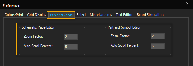
- Click OK.
Using Zoom Operations
In the schematic page editor and the part editor, you can zoom in to look closely at a particular area. You can also use other zoom functions, such as zoom out, zooming to a specific scale, or a selection, as required.
Zooming In
- To zoom in to the schematic canvas, press
I.
Capture centers your view on the current pointer position. If the pointer is outside the window or if you choose the Zoom In command or the toolbar button, Capture centers your view on the selected objects. Otherwise, Capture zooms in to the center of the active window. - To zoom into a specific object on the page, click a blank area close to the object and keeping the right mouse button pressed drag the area over the part you want to zoom into.
The area is zoomed into as soon as you release the mouse button. The zoom factor is3.
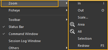
- To zoom in to an object, choose View – Zoom – In.
The current zoom scale is multiplied by the zoom factor. For example, a zoom factor of 2 causes the image to appear twice as large and displays half the area of the previous view.
Alternatively, hold down the CTRL key and roll up the mouse wheel.
Shortcut
Toolbar: 
Keyboard: I
Zooming Out
In the schematic page editor and the part editor, you can change your viewing perspective to increase the portion of the schematic page or part that is visible.
- To zoom out, choose View – Zoom and then choose Out.
The current zoom scale is divided by the zoom factor. So, for example, a zoom factor of 2 causes Capture to halve the image size and show twice the area of the previous view.
Alternatively, hold down the CTRL key and roll down the mouse wheel.
Shortcut
Toolbar: 
Keyboard: O
Changing the Zoom Factor
When you zoom in or out, the zoom scale is multiplied or divided by a zoom factor that you can set to suit your needs. Furthermore, you can set one zoom factor for the schematic page editor and another for the part editor.
To change the zoom factor, do the following:
- Choose Options – Preferences and then choose the Pan and Zoom tab.
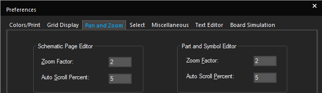
- In the Zoom Factor text box, specify the new zoom factor.
The zoom factor can be any number between 1 and 10.
Note that you can specify separate values for the schematic page editor and the part editor. - Click OK.
Zooming to a Specific Scale
To view a part or schematic page at a specific scale, do the following:
- Choose View – Zoom and then choose Scale.
- Select a preset scale or specify a custom scale.
- Click OK.
Viewing a Specific Area
To view a specific area of the schematic page editor or part editor, do the following:
- Choose View – Zoom – Area.
The pointer appears as a magnifying glass. - Move the pointer to one corner of the rectangular area to enlarge.
- Press and hold the left mouse button as you move the pointer to the opposite corner of the rectangular area.
- Release the mouse button.
The selected area fills the window.
Shortcut
Toolbar: 
Viewing the Entire Schematic Page or Part
You can view the entire schematic page at the same time. For a schematic page, Capture uses the dimensions set in the Page Size tab in the Schematic Page Properties dialog box
- Choose View – Zoom – All and the entire schematic page or part is reduced to fit the window.
Shortcut
Toolbar: 
Centering the View in Schematic Page Editor
You can center the view on your pointer or focus the view on a specific object.
To center the view on a specific object, do the following:
- Select one or more objects, or an area.
- Choose View – Zoom – Selection.
The display scrolls so that the selected objects are at the center of the window. The zoom factor does not change.
To center the view on your pointer, do the following:
- Move the pointer over the area to be centered.
- Press
SHIFT+Cor justC.
Refreshing the Display in Schematic Page Editor
To refresh the display, choose View – Zoom – Redraw.
Shortcut
Keyboard: F5
Magnifying Objects Using Fisheye
The Fisheye functionality provides a magnified view of the schematic to help you focus on a specific portion of the schematic. The two basic Fisheye features include Fisheye focus and the Dynamic Fisheye View mode.
Fisheye focus lets you set the focus to specific objects on your schematic. Setting the Fisheye focus to one or more objects on the schematic ensures that the selected objects are magnified. Meanwhile, the other visible objects are de-magnified. This ensures that you still have a view of the page, but the focus is on selective objects only.
Switch to Fisheye Mode
To use the Fisheye feature, you need to switch into the Fisheye mode. You can use the Fisheye mode to zoom into only specific objects on your schematic.
- To switch to the Fisheye mode, right-click the page and choose Fisheye view. Alternatively, choose View – Fisheye – Fisheye view.
Set Fisheye Focus
You set the Fisheye focus on a selected set of objects on your schematic. This results in only the selected objects to be zoomed in while the rest of the viewable area remains zoomed out.
To set the Fisheye focus, do the following
- Select one or more objects on the page.
UseCtrl +click to select multiple objects. - Right-click the page and choose Set Fisheye Focus.
The selected items are magnified on the screen.
Shift + F11 immediately sets the Fisheye focus on the selected object.Shortcut
Keyboard: Shift + F11
To remove the Fisheye focus, right-click the page and choose Reset Fisheye Focus.
Shortcut
Keyboard: Shift + Ctrl + F11
Fisheye Dynamic Focus Mode
In the Dynamic Fisheye focus mode, the focus of the page shifts as you move the mouse pointer across the page. As the mouse pointer hovers over a part of the page, only that part of the page comes into focus. The focus area is magnified while the rest of the viewable area appears zoomed out.
To set the Fisheye Dynamic Focus Mode, right-click the page and choose Fisheye Dynamic Focus Mode. Alternatively, choose View – Fisheye – Fisheye Dynamic Focus Mode.
Shortcut
Keyboard: Q
Zoom in Non-Linear Manner
In the Dynamic Fisheye mode, you can further zoom into or zoom out of the view to get higher or lower zoom factor as you pan across the page. The magnification factor ranges from a minimum of 2 to a maximum of 10. This feature is used in conjunction with the Set Fisheye focus and the Dynamic Fisheye View modes to further zoom into or zoom out of the schematic in a non-linear manner.
- To zoom in in a non-linear manner, press
Ctrl + +(Ctrl and plus key combination) - To zoom out in a non-linear manner, press
Ctrl + -(Ctrl and minus key combination)
Selecting and Deselecting Objects
You select objects to edit, move, or modify them in any way. You can simultaneously modify multiple objects if they are all in the selection set. Objects that are selected appear in the selection color. You can also control the selection of objects in a schematic page when you drag the mouse pointer diagonally across the schematic page.
- To select an object, position the pointer on the object, click the mouse or press the space bar.
The object appears in the selection color. Selection handles appear along the boundary box of an object selected in the schematic page editor. If the entire object is selected, all the selection handles are of the same size.
A large handle indicates the point at which the object is selected.
- To select objects that converge at a single location, click the point at which the objects converge to select all objects.
-
To select all the objects on a schematic page editor or in the part editor, choose Edit – Select All. Alternatively, press
CTRL + A.
-
To add or remove an object from the selection set, position the pointer over the object and press
Ctrland click the left mouse button simultaneously.
All objects in the selection set appear in the selection color. In the spreadsheet editor, this selection method is unavailable because the selection set is limited to contiguous cells.- When you open the part editor from the schematic page editor, the part you are editing cannot be selected on the schematic page. After you close the part editor window, the part can be selected.
- You can resize an object by selecting it at a single point and dragging.
Controlling the Selection of Objects
To control the selection of objects during a mouse-drag operation in the schematic page editor, do the following:
-
Choose View – Selection Filter.
The Selection Filter dialog box appears. - Select the check box corresponding to the object to be selected during the mouse-drag operation.
- Click OK.
The next time you drag the mouse pointer diagonally across a schematic page, only these objects will be selected in the schematic page.
Selecting all the Objects in an Area
To select all the objects in an area, do the following:
- From the tool palette, choose the Select tool.
- Move the pointer to one corner of the area.
- Keeping the left mouse button pressed, drag the pointer to the opposite corner, and release the left mouse button.
Every object in the selection set appears in the selection color and the set behaves as one object.
From the Options menu, choose the Preferences command, and then choose the Select tab.
Selecting a Contiguous Polyline
To select an entire contiguous polyline, do the following:
- From the tool palette, choose the Select tool.
- Keeping the left mouse button pressed, drag the pointer to select an area that includes some portion of the line.
Selecting from Overlapping Objects
To select from among overlapping objects, do the following:
- In the schematic page editor, position the pointer over the stack and press the
Tabkey while you click the left mouse button. This cycles through the objects in the stack. - In the part editor, press the
SHIFTkey and click the overlapped objects repeatedly to select each object one by one in rotation.
Selecting the Entire Net on a Schematic Page
To select all portions of a net on one schematic page, do the following:
- Select one segment of the net.
The segment changes to the selection color. - Right-click and choose Select Entire Net.
Deselecting Objects
- To deselect objects, click an area where there are no objects, or press the
Esckey.
Note that a part occupies a rectangular area encompassing all its graphics and property text, indicating that the part may occupy a larger area than is apparent.
- To deselect an object that you have just placed, select the selection tool before you click the mouse or press
ESCto end mode and pressESCagain to deselect the object.
Changing the Selection Color
To change the selection color, do the following:
-
Choose Options – Preferences.
-
Choose the Colors tab.
- Click the Selection color.
The color palette window opens. - Select the new color and click OK to close the color palette.
- Click OK.
Setting a Bookmark
A bookmark comes in handy if you find that you need to return repeatedly to a specific area of a schematic page or if you need to direct attention to a particular location. When you set a bookmark, you need to assign it a name. You can then use the Go To command to return to the location, and you can use the bookmark name to direct another member of your team to the location.
To place a bookmark, do the following:
- Choose Place – Bookmark.
- Enter the name of the bookmark.
- Click OK.
- Position the pointer where you want to place the bookmark and click the left mouse button.
The bookmark appears in the selection color. - Right-click and choose End Mode.
- Click an area where there are no parts or objects to deselect the bookmark.
To rename a bookmark, do the following:
- Select the bookmark.
- Choose Edit – Properties.
The Edit Bookmark dialog box appears. - Enter a new name in the text box and click OK.
Moving to a Location
To move to a specific location, such as grid coordinates, references, or bookmarks in an editor, use the Go To command. The Go To command is available from the right-click menus in the part and schematic page editors. The Go To command, with the Relative option selected, is useful for precise placement and spacing.
In the part editor, the Grid Reference and Bookmark tabs are not available in the Go To dialog box.
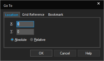
To move to a specific location, do the following:
- Choose View – Go To.
- In the Location tab:
- Specify the values for X and Y coordinates.
When moving to a specific location, note that the X and Y coordinates of the current location of the pointer appear:
- on the right-hand side of the status bar in the schematic page editor.
- on the bottom right corner of the part editor window.
- Select the Absolute option.
- Specify the values for X and Y coordinates.
- Click OK.
The coordinates are measured in inches or metric units, depending on what you specified in the Page Size tab of the Design Template or Design Properties dialog box.
The pointer moves to the new coordinates.
In the part editor, only the view moves to the given location and not the mouse pointer.
To move a specific distance, do the following:
- Choose View – Go To.
- In the Location tab:
- Specify the X and Y values that you want the pointer to move.
- Select the Relative option.
- Click OK.
The jump distance is measured in inches or metric units, depending on what you specified in the Page Size tab of the Design Template or Design Properties dialog box.
The pointer moves to the specified distance.
To move to a specific grid reference, do the following:
- Choose View – Go To.
- Select the Grid Reference tab.
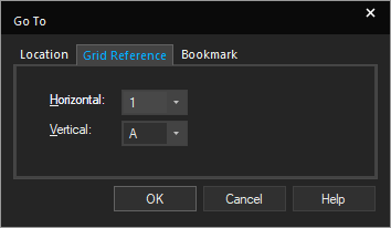
- Enter the horizontal and vertical information corresponding to the grid reference and click OK.
The pointer moves to the specified grid reference.
To move to a specific bookmark, do the following:
- Choose View –Go To.
- Select the Bookmark tab.
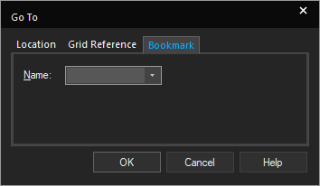
- Enter the name of the bookmark or select from the list.
- Click OK.
The pointer moves to the selected bookmark location.
Copying Objects
Capture supports the standard Cut, Copy, and Paste functions in all the editors. You can cut, copy, and paste information across schematic pages. You can copy text from other Windows applications and paste it into Capture text boxes. You can also copy a section of your schematic page to another Windows application.
Copy by Dragging
To copy and paste objects by dragging, do the following:
- Select the object or objects.
- Press and hold both the
Ctrlkey and the left mouse button while you drag a copy of the object to another location. - Release the left mouse button to place the copied object.
- If you drag a part or wire to another location and that change will affect connectivity, Capture warns you with a changed cursor and temporary markers on your schematic. Visible and off-screen connectivity changes will be saved in the session log if you complete the operation.
- Copying projects using
Ctrl+ drag causes duplicate instances, which creates problems for EDIF netlisting. If you run an EDIF netlist on a design in which you have used this method of copying objects, be sure to use instances when you annotate the design.
Using the Copy Command
To copy objects using the Copy command, do the following:
- Select the required object.
- Choose the Edit – Copy menu command.
The object is placed on the Clipboard. - If the object is to be copied to another window, open that window.
-
Choose the Edit – Paste menu command.
The object is attached to the pointer. - Move the pointer to the location where you wish to place the object and click the left mouse button.
The object appears in the selection color. - Click an area where there are no parts or objects to deselect the object.
- To place another copy of the object, repeat steps 4-6 above.
Copying to Other Windows Application
To copy text or graphics into other Windows applications, do the following:
- Select the text or graphic.
- Choose the Edit – Copy menu command.
The selected objects are copied to the clipboard - Open any Windows application and use that Paste command of the application to copy the contents of the clipboard.
Shortcuts
Toolbar: 

Mirroring Objects
Capture objects can be mirrored horizontally, vertically, or both. Some objects, such as text and images, cannot be mirrored.
To mirror objects, do the following:
- Select the required object.
- Choose the Edit – Mirror menu command.
If the commands of the submenu are not available, the object cannot be mirrored. - Choose Horizontally, Vertically, Both, as required.
The selected objects flip in the indicated direction.
Keyboard Shortcuts
- Mirror Horizontally:
H - Mirror Vertically:
V
Moving Objects
You can easily change the location of objects in the schematic page editor or the part editor. Immediately after you place an object, you need to select the selection tool or press Esc before you move any object.
Moving Objects Maintaining the Connectivity
To maintain connectivity as you move an object, do the following:
- Position the mouse pointer on the object.
- Holding the left mouse button down, drag the object to the new location.
- Release the mouse button.

Before Moving the Object After Moving the Object (Connectivity Maintained)
Moving an object this way does not break any of its electrical connections, with the exception of pin or net symbol connections. Otherwise, electrically connected objects are rubber-banded, that is stretched like rubber bands, to maintain the established net connectivity.
Moving Objects Without Maintaining Connectivity
To move an object in the schematic editor without moving the connected nets, do the following:
- Move the pointer over the object.
- Press
Altand click, and then drag the object to the new location. - Release the mouse button.
The object is placed at the new location. Nets previously connected to the object are not moved.
Loss of Connectivity after Moving the Object
Moving Objects Using Cut Command
To move objects using the Cut command, do the following:
- Select the required object.
- Choose Edit – Cut.
- If the object is to be moved to another window, open that window.
-
Choose Edit – Paste.
The object is attached to the pointer. - Move the pointer to the desired location to place the object and click the left mouse button.
The object appears in the selection color. - Click any blank area on the canvas to deselect the object, or press
Esc.
- In the schematic page editor, when you move an object in this manner, all occurrence properties are cleared, but instance properties are retained. See Part instances and Occurrences for more information.
- In the part editor, you can cut or copy objects and paste them in the part editor only. Similarly, you can cut or copy objects and paste them in the symbol editor only.
Rotating Objects
Schematic objects can be rotated by increments of 90-degrees. Some objects, such as images, cannot be rotated.
To rotate an object, do the following:
- Select the object.
- Choose Edit – Rotate.
The selection set rotates 90 degrees counterclockwise.
Rotate command does not appear on the Edit menu, the objects cannot be rotated.The pin names and pin numbers on the left and right side of a rotated part retain their default positions. For example, if a pin name is above the pin before a 180 degree rotation, pin name will be above the pin even after the 180 degree rotation as Capture retains the default position after rotation.
Shortcut
Keyboard: R
Working with Label States
During the design process, you may want to experiment with different what if scenarios to determine the best implementation for your purposes. Capture provides a method to do this with label states. You use Label states to define different states for a schematic page, perform edits, and then return to the defined state of the schematic before the editing occurred. Each schematic page can have its own set of label states. Further, each schematic page has two label states- Start and End-that are implicit. Label states are identified with a unique label consisting of one to five alphanumeric characters.
- As Start and End are default label states for each schematic page, any label state that you define cannot use the identifiers Start or End as labels.
- Labels are not case-sensitive. STATEA and stateA are considered identical by Capture.
To set a label state, do the following:
- Choose Edit – Label State – Set.
The Set Label State dialog box appears.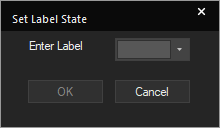
- Specify a name for the label.
Labels must be one to five characters long, and must be unique per schematic page. The labels Start and End are reserved and cannot be assigned. - Click OK.
The state of the schematic is labeled.
To go to a label state, do the following:
- Choose Edit – Label State – Goto.
The Goto Label State dialog box appears. - Specify the label of the state to which you want to return.
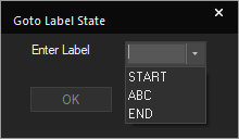
- Click OK.
The schematic revert to the labeled state. Any edits that occurred in the interim are removed.
To delete a label state, do the following
- Choose Edit – Label State – Delete.
The Delete Label State dialog box appears. - Specify the label for the state that you want to delete.
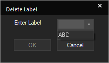
- Click OK.
The label state is removed and you can no longer return to it with the Goto Label State dialog box.
Working with VHDL and Verilog Files
Capture provides editing capabilities for developing VHDL and Verilog files. You can use this capability to create functional models for design behavior, or testbenches for simulation.
Creating a VHDL Model from a Hierarchical Block
In Capture, you can create VHDL models from hierarchical components on your schematic page. That is, you can create a hierarchical block on a schematic page, then create a VHDL model that defines its functionality. Creating VHDL models from hierarchical blocks in this manner is generally termed "top-down" design methodology.
To create a VHDL model from a hierarchical block, do the following:
- Open the parent schematic page in the schematic page editor.
- From the Place menu, choose the Hierarchical Block command.
Capture displays the Place Hierarchical Block dialog box. - Assign a reference designator to the hierarchical block in the Reference text box
- Choose VHDL as the implementation type from the Implementation Type drop-down list box.
- Specify the entity name for the VHDL model in the Implementation name text box.
- Specify a file name for the VHDL model that will define the behavior of the hierarchical block in the Path and filename text box.
The file name must be a VHDL file (*.VHD). - Click OK.
Capture returns to the schematic page editor. - Use the cursor to draw an outline for the block. Click at one corner of the desired area, drag the cursor to the opposite corner, and release it.
Capture places the outline of the block on the schematic page. - With the new hierarchical block selected, choose the Place Hierarchical Pin button from the tool palette.
Capture displays the Place Hierarchical Pin dialog box. - Assign a name to the pin, specify pin type and width, and click OK.
Note: Do not move the cursor outside of the schematic page editor window before completing the next step. - Move the cursor to the desired location in the hierarchical block and click to place the pin on the block.
- Right-click and choose End Mode from the pop-up menu.
- Repeat steps 9 through 12 to place additional hierarchical pins as needed.
- With the hierarchical block selected, right-click and choose Descend Hierarchy from the pop-up menu.
Capture generates a VHDL model template for the block using the hierarchical pins as port names. - Specify the functional description of the block in the model architecture.
- Close the VHDL editor.
- When prompted to save the changes to the file, click OK.
At this point, the hierarchical block is defined and ready to be wired in to the rest of the schematic.
Creating a Verilog Model from a Hierarchical Block
In Capture, you can create Verilog models from hierarchical components on your schematic page. That is, you can create a hierarchical block on a schematic page, and then create a Verilog model that defines its functionality. Creating models from hierarchical blocks in this manner is generally termed "top-down" design methodology.
To create a Verilog model from a hierarchical block:
- Open the parent schematic page in the schematic page editor.
- Choose the Place – Hierarchical Block menu command.
Capture displays the Place Hierarchical Block dialog box. - Assign a reference designator to the hierarchical block in the Reference text box
- Choose Verilog as the implementation type in the Implementation Type drop-down list box.
- Specify the module name for the Verilog module in the Implementation name text box.
- Specify a file name for the Verilog model that will define the behavior of the hierarchical block in the Path and filename text box.
The file name must be a Verilog file (*.V). - Click OK.
Capture returns to the schematic page editor. - Use the cursor to draw an outline for the block. Click at one corner of the desired area, drag the cursor to the opposite corner, and release it.
Capture places the outline of the block on the schematic page. - Choose the Place Hierarchical Pin button from the tool palette with the new hierarchical block selected.
Capture displays the Place Hierarchical Pin dialog box. - Assign a name to the pin, specify pin type and width, and then click OK.
Note: Do not move the cursor outside of the schematic page editor window before completing the next step. - Move the cursor to the desired location in the hierarchical block and click to place the pin on the block.
- Right-click and choose End Mode from the pop-up menu.
- Repeat steps 9 through 12 to place additional hierarchical pins as needed.
- With the hierarchical block selected, right-click and choose Descend Hierarchy from the pop-up menu.
Capture generates a Verilog model template for the block, using the hierarchical pins as port names. - Specify the functional description for the block in the model architecture.
- Close the Verilog editor.
- When prompted to save the changes to the file, click OK.
The hierarchical block is defined and ready to be wired in to the rest of the schematic.
Checking the Syntax of VHDL or Verilog Files
You can check the syntax of VHDL or Verilog files using the appropriate Check Syntax command. The tool checks the syntax in all the VHDL or Verilog files selected in the project manager window.
To check the syntax of VHDL files, do the following:
- In the project manager window, select the VHDL file for which you want to check the syntax. You can select multiple files using the Ctrl key.
- From the Edit menu, choose the Check VHDL syntax command.
The Check Syntax tool finds the first error in the file and highlights it so that you can fix it. - To continue checking the file, choose the Check VHDL syntax command from the Edit menu again.
Shortcuts
Shortcut menu: Check Syntax
To check the syntax of Verilog files, do the following:
- In the project manager window, click to select the Verilog file for which you want to check the syntax. You can select multiple files using the Ctrl key.
- From the Edit menu, choose the Check Verilog syntax command.
The Check Syntax tool finds all the errors in the file and highlights them so that you can fix them.
Further, Capture opens a text file, VAN.TXT, that contains details of all the errors in the netlist.
Shortcuts
Shortcut menu: Check Syntax
Moving Schematic Pages
You use schematic folders to organize a design by grouping schematic pages according to your requirements. If there is a change in the requirements, you can easily move schematic pages from one schematic folder to another. You can also place copies of pages in several schematic folders. You can move pages from one project to another, or you can place copies in both the projects. All the schematic pages must be contained in a schematic folder, a schematic folder to hold the pages must exist in the second project before you place the pages.
If a document in a schematic folder is open in an editor, the document cannot be moved or copied.
Moving Pages across Schematic Folders
To move schematic pages from one schematic folder to another, do the following:
- Verify that the pages are not open in the schematic page editor or the spreadsheet editor.
- In project manager, select the schematic pages you want to move.
- Choose Edit – Cut.
To retain a copy of the pages in both the schematic folders, choose Copy instead of Cut. - Select the schematic folder to store the pages.
- Choose Edit – Paste.
Alternatively, after selecting the schematic pages to be moved, drag them to the appropriate schematic folder.
Moving Pages across Projects
To move schematic pages from one project to another, do the following:
- Verify that the schematic pages are not open in the schematic page editor.
- Open a project and select the schematic pages you want to move.
- Choose Edit – Cut.
To retain a copy of the pages in both the projects, choose Copy instead of Cut. - Open the project in which you want to use the schematic pages.
- Select the schematic folder to store the pages.
- Choose Edit – Paste.
- Choose File– Save All. Do this for both the projects.
OR
- After ensuring that the schematic pages are not open in the schematic page editor, open both the projects in their respective project managers.
- Drag and resize the two project manager windows so that each is visible.
- Select the schematic pages that you want to move and drag them to the appropriate schematic folder in the second project manager window.
- To retail a copy of the pages in both the projects, press and hold
Ctrlwhile you drag the pages. - Choose File – Save All on both the projects.
- If you copy or move a document from one design or library to another, you must save the destination design or library immediately. Else, you may lose data when you open the moved document in the schematic page editor or part editor and then close the editor without saving the document.
- If you move or copy a parent schematic folder or schematic page from one project into a second project, Capture remembers the name and directory of the file containing the child schematic folder(s). This information is stored in the Attach Implementation dialog box for each hierarchical block and non-primitive part.
Renaming a Schematic Page
In Capture, the windows in which you work have headings based on the name of the open document. You can simplify your search through a set of open windows by using unique names for different documents. When you create a new part, symbol, schematic folder, schematic page, project, or library, you can specify a name or accept the unique name assigned by Capture.
To rename a schematic page, do the following:
- In project manager, select the document you want to rename.
- Choose the Design – Rename menu command. Alternatively, right-click the page in project manager and choose Rename.
The Rename Page dialog box is displayed,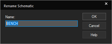
- Specify a new name and click OK.
The name change takes effect immediately.
Deleting a Schematic Page
To delete a schematic page, do the following:
- In project manager, select the page(s) to delete.
- Choose the Edit – Delete menu command. Alternatively, press the
Deletekey.
- You cannot undo the Delete Page command.
- You cannot delete schematic pages that are currently open. You must close all the open schematic pages to be deleted.
Closing and Saving a Schematic Page
- To close a schematic page, choose File – Close.
If the page contains unsaved changes, you will be prompted to save or discard the changes.
- To save changes to a schematic page, choose File – Save.
This saves only the current page and not the other pages in the design, even if you have edited them.
If you save a page in a design that has been upgraded from a previous release, you need to save the entire design. For an upgraded design, click Yes to create a backup when prompted and save all the pages with the changes.
View the next document: 08 - Working with Title Blocks
If you have any questions or comments about the OrCAD X platform, click on the link below.
Contact Us