14 - Generating Reports
Include File
You can use an include file to have the Bill of Materials command add information that is not in the schematic folder to the final bill of materials. You can create an include (.INC) file using any text editor that saves files in the ASCII format.
The first line of the include file is a header. The bill of materials is normally keyed to the part value, so the first line begins with a pair of single quotes with no spaces or other characters between them. The rest of the first line contains any information you want to include to make the file and the bill of materials more readable—this usually consists of headers for the values in the rest of the file.
The rest of the file contains a separate line for each part. Each line must begin with the property value (as specified in the Combined property string field within the Include File group box in the Bill of Materials dialog box) enclosed in single quotes. Following the property value (and on the same line) is the information that you want added to the bill of materials. You can separate the part value from additional information by inserting any number of spaces or tab characters—Capture will align the first non-blank character in each line when it creates the bill of materials report.
You must separate the items in the Combined property string field in the Bill of Materials dialog box exactly as they are separated in the include file. For example, if you use a space to separate the part values, descriptions, and part orders, then the combined property string should look like this:
{Value}Example
'' DESCRIPTION PART ORDER CODE
'1K' Resistor 1/4 Watt 5% 10000111003
'4.7K' Resistor 1/4 Watt 5% 10000114703
'22K' Resistor 1/4 Watt 5% 10000112204
'1uF' Capacitor Ceramic Disk 10000211006
'.1uF' Capacitor Ceramic Disk 10000211007
Creating a Bill of Materials
A bill of materials is a composite list of all the elements you need for your PCB design. Using the Bill of Materials command, you can create a standard tab-delimited part list, or you can create a custom bill of materials showing properties that you specify. With either of these formats, you can add information about any part by merging an include file with your bill of materials. A standard bill of materials includes the item, quantity, part reference, and part value.
Capture automatically elects to use either instances or occurrences for generating reports, depending upon your type of design. In general, you should use instances for FPGA and PSpice projects, and use occurrences for PCB and Schematic projects.
You can create non-electrical parts—such as screws, washers, and sockets—that will appear in a bill of materials report but not in a netlist because the non-electrical parts do not have pins. Any part without pins is considered non-electrical.
You can specify any header information you want. The header of a bill of materials usually contains information such as the design name, date, document number, revision code, report name, page number, and the time the report is created. If the Header field contains only a single space character, the header is left blank.
Capture report files are text files, and can be opened in any text editor. You may want to use the tab alignment capability of your word processor to line reports up correctly. Spreadsheets will automatically align the columns of Capture-generated report files.
To create a Bill of Materials, do the following:
- In the project manager, select schematic folders or schematic pages if you want to process only a portion of the design. If you want to process the entire design, leave the schematic folders or schematic pages unselected.
- From the Tools menu, choose the Bill of Materials command.
The Bill of Materials dialog box appears. - Verify that the dialog box options are set the way you want them.
For example, you specify whether you want to process the entire design or only the selected schematic folders or schematic pages, and the name and location for the report file.
(If you want to customize the information contained in the bill of materials report, see To create a custom bill of materials below.) - Click OK.
To merge information from an external database, do the following:
- Create an include file.
- Perform the steps listed in To create a bill of materials section and set these additional options in the Bill of Materials dialog box.
- Select the Merge an include file with report option.
- Specify a combined property string.
- Specify the path and name of the include file.
To create a custom bill of materials, do the following:
- Perform the steps in To create a bill of materials section and set these additional options in the Bill of Materials dialog box:
- In the Header field, enter the column headings you want in the report. If you leave the Header field blank, there are no column headings in the report.
- In the Combined property string field, enter the names of the properties you want in the report. If you want the property values separated by literals, include the literals in the field.
To import the bill of materials in Microsoft Excel, do the following:
- Select the Open in Excel check box.
- Click OK.
The bill of materials is displayed in the Microsoft Excel spreadsheet.
Shortcut
Toolbar: 
Example
1 Bit Full Adder Hierarchy (COMPLEX) Revised: March 31, 1999 OrCAD
Bill Of Materials March 31, 1995 16:50:31 Page 1
|
Item |
Quantity |
Reference |
Part |
|
1 |
1 |
U1 |
74LS32 |
|
2 |
3 |
U2 |
74LS08 |
|
U2 |
74LS08 |
||
|
U2 |
74LS08 |
||
|
3 |
2 |
U3 |
74LS04 |
|
U3 |
74LS04 |
Creating a Cross Reference Report
The Cross Reference tool creates a report, indexed by schematic page, of all the parts with their part references, part names and libraries. You may specify that the report should also list the unused parts in multiple-part packages and the coordinates of all parts.
Capture automatically selects either instances or occurrences for generating reports depending upon the type of design with which you are working. In general, you should use instances for FPGA and PSpice projects, and use occurrences for PCB and Schematic projects.
To create a cross reference report, do the following:
- In the project manager, select schematic folders or schematic pages if you want to process only a portion of the design. If you want to process the entire design, leave the schematic folders or schematic pages unselected.
-
From the Tools menu, choose the Cross Reference command.
The Cross Reference Parts dialog box displays.
- Verify that the dialog box options are set the way you want them. For example, you specify, among other things, whether you want to process the entire design or only the selected schematic folders or schematic pages, whether the parts are sorted by part value or by part reference, and the name and location for the report file.
- Click OK.
- The Cross Reference command generates report files with .XRF or .CSV extensions.
- Capture report files are text files and can be opened in any text editor. You may want to use the tab alignment capability of your word processor to line reports up correctly. Spreadsheets will automatically align the columns of Capture-generated report files.
- The path listed in the Library column of the Cross Reference report represents where the part placed was found when it was originally placed. If you change machines, move or delete the library, or rename the part, the information in the report won't correspond to the current path and file name.
Shortcut
Toolbar: 
Example
1 Bit Full Adder Hierarchy (COMPLEX) Revised: March 31, 1995 OrCAD
Design Name: C:\CAPTURE\DESIGN\FULLADD.DSN
Cross Reference March 31, 1995 16:15:54 Page 1
|
Item |
Part |
Reference |
Schematic Name |
Sheet |
Library |
|
1 |
74LS04 |
U3A |
HALFADD |
1 |
C:\WINDOWS\TEMP\TTL.OLB |
|
2 |
74LS04 |
U3B |
HALFADD |
1 |
C:\WINDOWS\TEMP\TTL.OLB |
|
3 |
74LS08 |
U2A |
HALFADD |
1 |
C:\WINDOWS\TEMP\TTL.OLB |
|
4 |
74LS08 |
U2B |
HALFADD |
1 |
C:\WINDOWS\TEMP\TTL.OLB |
|
5 |
74LS08 |
U2C |
HALFADD |
1 |
C:\WINDOWS\TEMP\TTL.OLB |
|
6 |
74LS32 |
U1B |
HALFADD |
1 |
C:\WINDOWS\TEMP\TTL.OLB |
Creating a Placement Report
You can generate a report of the X and Y locations of the placements of the parts on a schematic.
This report, generated as a .CSV file, provides the following details of the parts:
- reference designator
- part name
- schematic name
- sheet number
- file system location of the part library
- X co-ordinate location
- Y co-ordinate location
To Create a Placement report, do the following:
- You can create this report at any level of a design hierarchy: design, folder or page. Therefore, you need to select the appropriate level of the hierarchy in the part manager.
- Right-click on the Project manager and choose Reports – Export Placement.
The Placements.csv file is created at the same file system location as the current design and simultaneously opened for viewing.
While the report is generated at any level of the design hierarchy, you can also multi-select parts of the hierarchy to generate the report. For example, you can select multiple pages to generate a placement report of only the parts on the selected pages.
Creating a Find Results Report
You can create a report for the results of the Find command. This report can be output in either the CSV or HTML formats.
Also, when you run the Find command to search for different types of objects, the search results appear in various tabs of the Find Results window. In this case, you can export the data from each tab.
To create a Find Results report, do the following:
- Select Edit – Find, or press
CTRL+F. - Right-click any search result row from the Find Results window, and choose Save as HTML or Save as CSV.
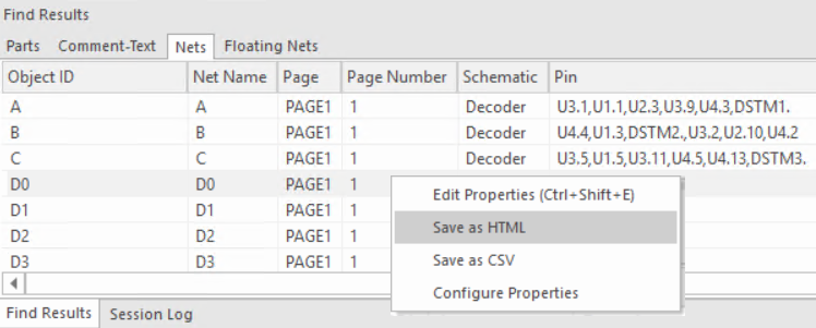
A message box opens showing the file system location of the report. - Click OK.
Check and Save
After you run the design rule check at least once on a design, you can then use the Check and Save command. This command executes the electrical Design Rules Check on the current set of electrical design rules that you have already defined in the Design Rules Check dialog box.
To run the Check and Save command:
- Select the design from the project manager pane.
- Select File – Check and Save.
The DRCs window in the output area displays a list of electrical DRC errors and warnings generated from the running Design Rules Checks.
It also displays the DRC markers on the schematic design. - Double-click an error or warning in the listings to go to the DRC marker on the specific schematic page.
You need to setup and run the design rules check at least once before using the Check and Save command.
View the next document: 15 - Printing and Plotting
If you have any questions or comments about the OrCAD X platform, click on the link below.
Contact Us