08 - Interfacing PSpice Designs in MATLAB
This chapter explains how to prepare PSpice circuits by creating CIR files and describes the various options of the Co-Simulation Settings window. It also explains the data exchange between Simulink and PSpice:
- Using the Co-Simulation Settings Window
- Setting up Simulink Simulations
Using the Co-Simulation Settings Window
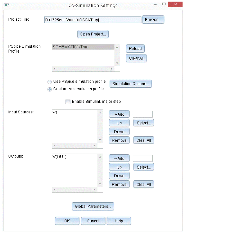
You can open the Co-Simulation Settings window by double-clicking the PSpice Block in the Simulink project window, as shown in Figure 8-1.

Figure 8-1 Co-simulation Settings window
The Co-simulation Settings window allows you to specify the following parameters for the PSpice block:
- Project File: Designates a Capture project file (*.opj) containing a PSpice schematic to be assigned.
- Open Project: Opens the designated project in Capture. If a project has not been designated, Capture will open without a project. You cannot use this button to open a designated project if Capture has already started. Either close Capture before clicking this button, or manually open the designated project from Capture.
If Capture is already open when you start Capture by pressing click Open Project from Co-Simulation Settings, you cannot open a project.
- Reload: Updates information about changes done in the schematic.
- Clear All: Clears the items in the Co-Simulation Settings window.
- PSpice Simulation Profile: Lists all simulation profiles in the project specified in the Capture Project File text box.
- Use PSpice simulation profile: Uses the default simulation profile settings.
- Customize simulation profile: Allows you to use the customized simulation settings.
- Simulation Options: Allows you to customize the co-simulation settings using the Simulation Settings dialog box. For more information on simulation settings dialog box parameters, see the Options and Data Collection in Simulation Settings chapter.
- Enable Simulink major step: Select this check box to enable Data Exchange between Simulink and PSpice only at Simulink major steps. Selecting this option may increase the transient timing error between Simulink and PSpice. However, calculation time may be shorter because of a decrease in the number of calculation steps, that is, data exchanges between Simulink and PSpice.
- Input Sources: Designates the voltage source (V*) and current source (I*) for supplying input data (from Simulink to the PSpice block) into the circuit. If a voltage source is selected, the input data will be supplied to the circuit as a voltage value, and if a current source is selected, it will be supplied as a current value. The sequence listed here is the sequence of input signals to the PSpice block. At least one input source must be specified.
- Inputs: Click Select in the Input Sources section to open this dialog box. It lists all power sources contained in the circuit referenced by the CIR file specified in the PSpice Simulation Profile list box.
- Add/Up/Down/Remove buttons for Input Sources: Adds, changes sequence, and deletes items, respectively, from the Input Sources list box.
- Outputs: Designates data in the circuit to be output from the PSpice block to Simulink. The sequence listed here is the sequence of output signals to Simulink. You can set node voltage, current passing through a device, and dissipation of a device as values for the PSpice Simulink Co-simulation output. The specification format for output values corresponds to that of PSpice.
- Node voltage:
Specified by the syntax: V([NODENAME])
Where NODENAME is the name of the node in the circuit. - Current passing through a device or pin inflow current:
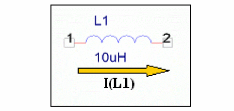
Specified by the following syntax: I ([DEVICENAME]:[PINNAME])
Where DEVICENAME is the reference name of the device and PINNAME is name of pin whose current is referred.
Example 1:
I(Q1:B)
Where:- Q1 is the device name
- B is the pin name
I(VDC:+)
Where:- VDC is the device name
- + is the pin name

- Power dissipation of device:
Specified by the syntax: W([DEVICENAME])
Power dissipation is calculated as I*V. However, since the absolute value of current is taken, the current directions do not matter.
- Node voltage:
- Outputs: Click Select in the Outputs section to open the Outputs dialog box. It lists all output variables in the simulation profile specified in the PSpice Simulation Profile list box.
- Add/Up/Down/Remove buttons for Outputs: Adds, changes sequence, and deletes items, respectively, from the Outputs list box.
- Global Parameters: Click this button to specify if any global parameters are defined in the design.
Data Exchange between Simulink and PSpice
When a PSpice block is placed in a Simulink model, two different analysis engines are used for simulation, where transient analysis will be done at their respective time step.
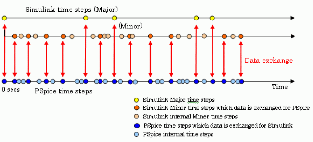
Data exchange between Simulink and PSpice A/D via PSpice Simulink Co-simulation is shown in the following figure:

In Simulink, you cannot check an internal property of PSpice that has a smaller time step than that of Simulink. In addition, there are also some Simulink minor steps for which data is not exchanged with PSpice, as you can see from the figure above.
To check the internal results of PSpice, designate one of the items other than None under Data Collection in the Simulation Settings window. Then use PSpice A/D to open the PSpice data file Tran_slps__SLPS.dat after completing an analysis.
Setting up Simulink Simulations
You can use the Configuration Parameters dialog box to specify the settings for the Simulink simulations. To open this dialog box, in the Simulink model window, select Simulation – Model Configuration Parameters.
PSpice Simulink Co-simulation can use any one of the items from the Type list under Solver options:
- Fixed-step
- Variable-step
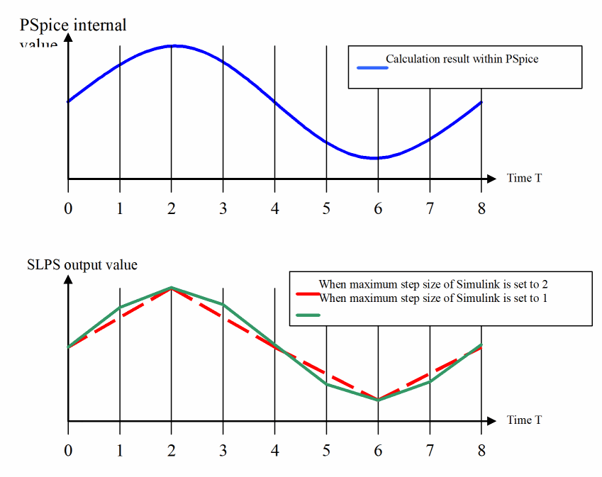
Because PSpice Simulink Co-simulation data exchange only operates with each Simulink step, in order to avoid overlooking phenomena from the PSpice circuit, Simulink’s maximum step size (Simulink’s fixed step size when fixed step is selected) must be a sufficiently small value. The value, however, should not be smaller than is needed, or Simulink’s overall analysis may become slow.
As you can see from Figure 8-2, you cannot obtain the correct waveform if the maximum step size is set to a large value.

Figure 8-2 Waveform with large maximum step size value
If you want to see a waveform within PSpice in order to determine the step size, check it by starting PSpice A/D and opening the PSpice data file, though it will not be displayed in Simulink.
When the PSpice block is inserted in the feedback loop, calculation in the PSpice block is performed by PSpice, which operates in a different memory space than that of Simulink. In principle, a delay of one Simulink cycle step will occur between the PSpice block's input and its output. To minimize this effect, Simulink’s time steps must be sufficiently small.
View the next document: 09 - Analyzing Simulink Models
If you have any questions or comments about the OrCAD X platform, click on the link below.
Contact Us