05 - Working with Designs
Overview Creating a Design Opening a Design Creating a new VHDL or Verilog file Creating a Text File Non-Electrical Objects in a Design Flat and Hierarchical Designs Browsing in Capture Searching in Capture Renaming a Design Saving and Closing a Design Compare Designs Exporting and Importing ad Design from XML Reviewing Designs using Comments and Markups in OrCAD X Capture
Overview
You create schematic designs in Capture. There can be only one design file in a project. If you do not specify a root for your design, no reports are generated for the design. Also, when folders are copied to a new design, the ROOT designation is lost and must be reestablished in the design.
Schematic designs can include either VHDL or Verilog models, but not both as lower-level hierarchical modules. However, these models can only instantiate other models of the same type at lower levels in the hierarchy.
Consider the following illustration:
Any schematic design module can include either schematics, or VHDL or Verilog models as instantiated components. However, VHDL or Verilog design modules are limited to other modules of the same type as instantiated components. Therefore, if the root module of a design is a VHDL model, all the lower-level modules must also be VHDL modules.
Creating a Design
When you create a project in Capture, a design with the same name as the project is immediately created for you.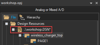
However, you also have the option of creating a design without first creating a project.
- To create a design without first creating a project, choose the File – New – Design menu command from the main menu.
The project manager opens a new panel for the new project structure. By default, the new project is named Design<n>.opj and a new design with the name Design<n>.dsn is created. The design is created in the Windows\temp directory. Capture checks if a file with an identical name exists in the temp directory. If it exists, the number, <n>, in the design name is incremented by one. A design created this way cannot be renamed.
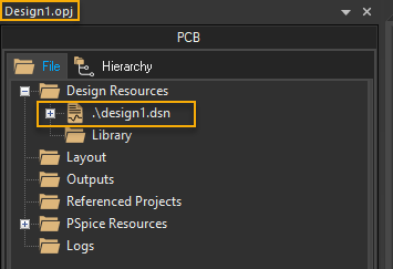
A schematic folder within the design file is also created with a schematic page within the folder. The schematic folder icon is marked with a backslash character (\) to signify that it is the root schematic folder. You can view the hierarchy in the File tab of the project manager.
- A new design inherits characteristics from the settings in the Design Template dialog box, you need to check those settings before you create a design.
- A design file (
.dsn) cannot exist without a container project (.opj). - There can be only one design file in a project. If you create a new design file, or move or copy a different one into the project, the project manager prompts you to replace the existing design file.
Opening a Design
When you create a design in Capture, all the schematic information defined in it is recognized as part of the project. When you open the design, all such data is automatically associated with it.
To open a design, do the following:
- Choose the File – Open menu command.
The standard Open dialog box displays. - If the design is not in the current folder, use the Look in drop-down list to navigate to the design folder.
- In the Files of type drop-down list, select Capture Design (*.dsn).
- Select the design from the files and folder list or enter the name of the design in the File name text box and click OK.
You can use the standard * (asterisk) or ? wildcard characters when typing in the File name text box.
The design opens in the project manager window.
Shortcut
Toolbar: 
To open a recently used project, choose the File menu followed by the project either by the name or by the number.
The project opens in a separate instance of the project manager window.
The Select Project Type dialog box opens if you open a design in Capture that does not have an associated project. You then select the simulation option and Capture creates the corresponding project file (.opj).
Creating a new VHDL or Verilog file
You can create VHDL or Verilog files as part of the functionality description of a design, or as test benches for simulation with NC VHDL or some other simulator. You can also instantiate lower-level VHDL or Verilog files within a VHDL or Verilog file.
To create a new VHDL or Verilog file, use one of the following ways:
- Choose File – New – VHDL File or File – New – Verilog File from the main menu, as required.
A file of the appropriate type opens as a new tab.
OR
- With the project manager active, choose Design – New VHDL File or Design – New Verilog File.
The file opens in the appropriate editor and a dialog box appears, asking if you want to add the file to the project. - Select the Yes button to add the file to the current project.
The Save As dialog box appears.
If you select No, the file is not added to the project. You need to save the project later. - Select a directory for the file and provide a filename.
By default, a VHDL file is namedVHDLn.VHD, wherenis an integer indicating the number of.VHDfiles created in the current session. Similarly, a Verilog file is namedVerilogn.V. - Click Save.
The file is saved and appears in the Design Resources folder in the project manager.
Creating a Text File
To create a text file from the project manager, do the following:
- Choose the File – New – Text menu command.
- Specify the desired text.
- Close the text session when you are done.
Capture prompts you to save the text file. - To save the file, specify a file name and a location to store the file.
Non-Electrical Objects in a Design
Text and graphics in schematics are considered as non-electrical components used for documentation purposes. You can use the text and drawing objects provided in Capture to provide additional information on the schematic and create graphical objects on the schematic, respectively. These objects provide a way for you to document your schematic without affecting its connectivity. They do not have any effect on the netlist generated from the schematic.
Topics covered in this section:
- Creating Graphics
- Drawing Arcs
- Drawing Bezier Curves
- Drawing Ellipses and Circles
- Drawing Elliptical Arcs
- Drawing Lines
- Drawing Polylines
- Drawing Rectangles and Squares
- Placing OLE Objects
- Placing Pictures
- Placing Text
- Placing IEEE Symbols
Creating Graphics
You can create a wide variety of graphic shapes for the parts to be used in a design. You can make use of some preferences options and commands available in Capture to create graphics with ease, such as the snap-to-grid option, Zooming in on the object, or the View - Go To menu command.
Before you begin drawing, you can specify the default line and fill styles because all lines and shapes you draw adopt the current line style, and closed shapes adopt the current fill style. You can use a variety of line types or fill styles for any schematic page or part.
Setting Default Graphic Attributes
To change the snap-to-grid option, do the following:
- Choose the Options – Preferences menu command.
- In the Preferences dialog box, select the Grid Display tab.
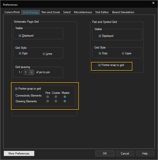
- Set the Pointer snap to grid option separately in the Schematic Page Grid and Part and Symbol Grid sections.
To set default line and fill styles, do the following:
-
In the Preferences dialog box, select the Miscellaneous tab.
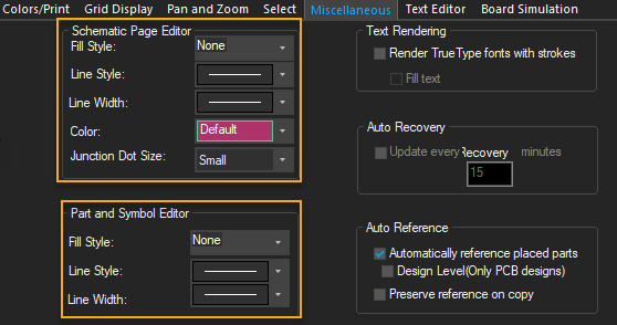
Note that you can specify separate options for the schematic page editor and the part and symbol editor. - Click the Line Style and Line Width drop-down list to display the options.
- Select the desired option and click OK.
Any lines or shapes you draw will have this line style. - Click the Fill Style drop-down list to display the options.
- Select one of the options and click OK. Any closed shapes you draw will have this fill style.
To edit line style or fill style of a placed object, do the following:
In the Schematic Page editor, do the following:
- Select the required object.
- From the Edit menu, choose the Properties command.
- In Property Editor, select another line style or fill style and click Apply.
In Part editor, do the following:
- Select the required object.
- Use the Basic Attributes section in the Property Sheet pane to modify the line style or fill style.
To draw an object, do the following:
- From the Place menu, choose the appropriate drawing command or select the appropriate drawing tool from the tool palette.
- Use the mouse to draw the object.
- To constrain the object by the orthogonality rules, press and hold the
Shiftkey while you draw.
Drawing Arcs
You create an arc of any angle using the arc tool. Arc is a line and adopts the current line style.
To create a full circle, use the ellipse tool.
To draw an arc, do the following:
-
Choose the Place – Arc menu command.
-
Move the pointer to the location where you want to start the arc.
The arc is drawn counterclockwise from this start point. -
Drag the mouse to define the shape of the arc.
-
Release the left mouse button to mark the end of the arc.
The arc appears in the selection color.
-
Choose the selection tool or press
ESCto dismiss the arc tool.
Shortcut
Tool palette: 
Drawing Bezier Curves
Bezier curves are defined using a start point, two control points and an end point. The two control points define the gradient of the curve. These two points control the shape of the curve. The entire curve is a blend of the four points that make up the curve.
To draw a Bezier curve, do the following:
- Choose the Place – Bezier Curve menu command.
- Click the canvas to mark the start point of the curve.
- Click to mark the first control point.
- Click again to mark the second control point.
- Click to mark the end point of the curve.
- Press
Escto dismiss the Bezier curve tool.
Extending the Four-Point Curve
To extend a four-point curve, do the following:
- After you have drawn the four points of the Bezier curve, mark a fifth point on the canvas.
Note that the shape from the fourth to the fifth point is a straight line. Here the end point of the first curve is the start point of a second four-point curve. - Continue to make any number of four-point Bezier curves, each starting and the end of the previous curve.
Also note that the point connecting two contiguous four-points curve forms a sharp edge. - Select and move this point to smoothen out this edge, if required.
This way you can create a curve with any number of control points.
Editing Bezier Curve
To edit a Bezier curve, do the following:
- Select and move the start or end points of the curve to alter the start or end positions of the curve.
- Select and move the two control points of the curve to alter its gradient.
Shortcuts
- Tool palette:

- Keyboard:
SHIFT+Q
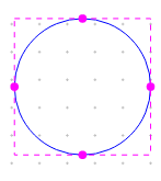
Drawing Ellipses and Circles
You use the Ellipse tool to draw an ellipse or a full circle. Circles and ellipses are closed shapes, so they use the current fill and line style.
To draw an ellipse or a circle, do the following:
-
Choose the Place – Ellipse menu command.
- Move the pointer to an edge of the intended ellipse.
- Press and hold the left mouse button while dragging the mouse. Alternatively, click the left mouse button and move the mouse to a new location.
The ellipse changes shape as you move the mouse. - Release the left mouse button when you have the correct shape.
- To draw a circle, hold down the
Shiftkey while you perform this step.
The ellipse or circle appears in the selection color. - Choose the selection tool or press
Escto dismiss the ellipse tool. - Click an area where there are no parts or objects to deselect the ellipse.
Shortcuts
- Tool palette:

- Keyboard:
SHIFT+F
To edit an ellipse or a circle, do the following:
- Select an ellipse.
When you select an ellipse, four handles are made visible around the shape. - Click and drag any of these handles to alter the shape.
Drawing Elliptical Arcs
You create an elliptical arc of any angle using the elliptical arc tool. Arc is a line, so it adopts the current line style.
To create a full ellipse, use the ellipse tool.
To draw an elliptical arc, do the following:
-
Choose the Place – Elliptical Arc menu command.
-
Move the pointer to the start location of the arc.
The arc is drawn counterclockwise from this start point. -
Drag the mouse to define the shape of the arc.
-
Release the left mouse button to mark the end of the arc.
The arc appears in the selection color.
-
Choose the selection tool or press
ESCto dismiss the arc tool.
Shortcuts
- Tool palette:

- Keyboard:
SHIFT+T
Drawing Lines
You use the Line tool to draw a single line. The line you draw adopts the current line style.
If you want to draw a line with multiple contiguous segments, use the Polyline tool.
To draw a line segment, do the following:
- Choose the Place – Line menu command.
- Move the pointer to the beginning of the line.
- Press and hold the left mouse button while moving the mouse to draw the line and release the left mouse button to end the line.
Alternatively, click the left mouse button, move the mouse, and click the left mouse button again to end the line.
The line appears in the selection color. - Select the selection tool or press
ESCto dismiss the line tool. - Click an area where there are no parts or objects to deselect the line.
Shortcuts
- Tool palette:

Drawing Polylines
To draw a line with multiple contiguous segments, use the Polyline tool. The line you draw adopts the current line style. Polygons can be created with the Polyline tool. The polygons adopt the current fill style.
Drawing polylines is similar to placing wires. Polylines automatically default to drawing with square corners. You can draw non-orthogonal polylines by holding the SHIFT while you draw.
To draw a polyline, do the following:
- From the Place – Polyline menu command.
- Click the left mouse button to begin drawing, click to change directions, and double-click to end the final segment.
To constrain the direction changes to multiples of90 degrees, pressSHIFT. After you double-click, the polyline appears in the selection color. - Click an area where there are no parts or objects to deselect the polyline.
- Select the selection tool or press
ESCto dismiss the polyline tool.
To draw a polygon, follow the above-listed instructions, ending the line with a single mouse-button click at the beginning point. The polygon adopts the current line and fill style.
Shortcuts
- Tool palette:

- Keyboard:
Y
Drawing Rectangles and Squares
You use the rectangle tool to create orthogonal shapes; if you wish to create a polygon, use the polyline tool.
Any rectangles or squares you create will have the current fill style and line style.
To draw a rectangle or a square, do the following:
-
Choose the Place – Rectangle menu command.
- Move the pointer to one corner of the intended rectangle.
- Press and hold the left mouse button while you drag the mouse. The rectangle changes shape as you move the mouse.
- Release the left mouse button when you have the correct shape.
Alternatively, click the left mouse button and move the mouse to a new location, and click the left mouse button when you have the intended shape and size. - To draw a square, hold down the
Shiftkey while you perform this step.
The rectangle or square appears in the selection color. - Choose the selection tool or press
Escto dismiss the rectangle tool. - Click an area where there are no parts or objects to deselect the rectangle.
Shortcuts
- Tool palette:

- Keyboard:
SHIFT+R
Placing OLE Objects
You place objects of other applications on your schematic page using the OleObject command. Using this command, you can embed or link an external application file into your schematic page. This provides the ability to package other files (or links to files) along with your schematic. For example, you can embed a PDF document on a schematic page or place and link an Excel document on a page. You can add an existing external file to your schematic as an OLE object. Alternatively, you can add a new instance of an application file.
To place a new OLE object on a page, do the following:
- Choose Place – OleObject.
The Insert Object dialog box opens.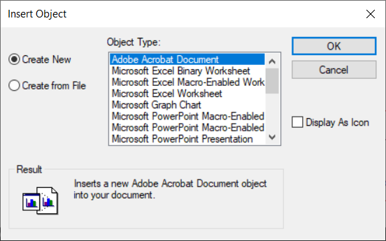
The Create New option is selected by default. - From the Object Type list, choose the new object type to embed on the schematic page.
Choose only the object types for which you have the associated application installed on your system. - Click OK.
The cursor changes into the cross-hair cursor indicating that Capture is now in the Place OLE Object mode. - Click the mouse button at the point where you want to start the object and drag the cursor to draw a rectangular area to contain the object.
Notice that as soon as you release the mouse button, an instance of the container application opens within Capture, which includes all the toolbar of the application associated with the OLE object type. For example, if you select Bitmap Image type, the displayed toolbar is the Microsoft Paint toolbar.
You can now make changes to the OLE object using the associated application toolbar and edit features from within Capture. - When you are done making changes to the new object, click anywhere on the schematic page outside the object.
The OLE object is now embedded in your schematic page and the contents will be saved along with your schematic page.
To edit the OLE object, double-click the object in the schematic page, an instance of the associate application is opened within Capture and you can now make the desired changes to the object.
To place an existing OLE object on a page, do the following:
- Choose the Place – OleObject menu command .
The Insert Object dialog box displays. - Select the Create from File option.
You can either specify the name of the file or browse to the location of the file on the system. - Choose the Link option to embed a reference of the file, else the file itself is embedded on your page.
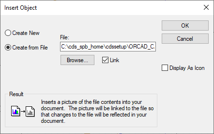
- Choose the Display As Icon option to display the icon for the application associated with the file.
- Click OK.
The cursor changes into the cross-hair cursor indicating that Capture is now in the Place OLE Object mode. - Click the mouse button at the point where you want to start the object and drag the cursor to draw a rectangular area to contain the object.
- When you are done making changes to the new object, click anywhere on the schematic page outside the object.
The file you selected is either embedded or linked on your schematic page.
If you choose to embed a file, any changes to the original file are not reflected on the OLE object on the schematic page. However, if you link the file, any changes you make on the OLE object on the schematic page are reflected on the file (available on the file system). Also, any change you make on the file on the file system is reflected on the OLE object on your schematic page.
Placing IEEE Symbols
You can place IEEE symbols to represent mechanical components. These symbols do not have an effect when you generate a netlist for your schematic.
To place an IEEE symbol in the part editor, do the following:
- Choose Place – IEEE Symbol.
The Place IEEE Symbol dialog box appears. - From the Select IEEE Symbols list, select a symbol.
The symbol appears in the preview box. - Select the required symbol and click OK.
The symbol is attached to your pointer. - Move the mouse pointer to move the symbol and click to place the symbol.
- Select the selection tool to dismiss the symbol tool or repeat step 4 to place additional symbols.
Shortcuts
- Tool palette:

- Keyboard:
SHIFT+X
Flat and Hierarchical Designs
Flat Designs
For schematic designs, flat designs are structures in which the output signals of one schematic page connect directly to the input signals of another schematic page in the same schematic folder through off-page connectors.
A flat design has no hierarchy—no hierarchical blocks, ports, pins, or parts with attached schematic folders. All schematic pages in a flat design are contained within a single schematic folder. Regardless of the number of schematic pages in a flat design, all parts appear at the same level of hierarchy in the Hierarchy tab.
In a flat design, all the interconnections between the pages are managed using the names assigned to the off-page connectors; it is best to keep a flat design relatively small.
For VHDL models, flat designs are implemented in a single entity or architecture pair. The entire functionality of the design unit is described within the VHDL architecture. For example:
architecture behavior of Dtype is
begin
 process (ck)
 begin
 if (ck = '1') and ck'event then
 q <= d;
 end if;
 end process;
end behavior;
Hierarchical Designs
What are Hierarchical Designs?
You can manage both schematic and VHDL design resources in a hierarchical manner by creating schematic pages containing hierarchical blocks or parts with schematic or VHDL implementations. The hierarchical block symbol (a part with an attached schematic page or model) in the schematic page editor is the primary mechanism to extend the scope of the design. Hierarchical blocks are used to partition the major functional regions of a design using a block diagram.
Any schematic page can contain combinations of hierarchical blocks or parts that refer to other schematics or VHDL source files. This nested structure can be several levels deep.
The schematic folder or VHDL entity at the top of a hierarchy, which directly or indirectly refers to all the other modules in the design, is called the root module. In the File tab of the project manager, the root module has a backslash on its folder icon. The root module folder, as well as any other module folder, can contain as many schematic pages or VHDL models as you require. Capture also supports a combination of flat and hierarchical structures such that a schematic folder containing multiple schematic pages may be associated with a hierarchical block or part.
Simple Hierarchies
A one-to-one correspondence between hierarchical blocks or parts and the schematic, EDIF, or VHDL implementations they reference is called a simple hierarchy. The following image is an example of a simple hierarchy typical of most PCB designs in Capture:
In a simple hierarchy, each hierarchical block or part with an attached schematic folder or VHDL model represents a unique design module. The Hierarchy tab of the project manager displays a simple hierarchical design as a tree of schematic pages.
Complex Hierarchies
A complex hierarchy is one that includes a many-to-one correspondence between the hierarchical blocks or parts and their implementations—schematic, EDIF, or VHDL. The following image is an example of a complex hierarchy typical of most programmable logic designs in Capture. As shown in the image, two hierarchical blocks (H1 and H2 on schematic D) reference the same schematic (schematic E).
Editing Hierarchical Block Look and Feel
When you create a hierarchical block on a schematic page, the block displays the part name and the implementation. However, you may want to add a picture to the block that acts as a visual representation of the implementation below the block.
To place a graphical object on a hierarchical block, do the folloiwng:
- Select the hierarchical block.
- Right-click the block and choose Edit Part.
The block opens in Part Editor. -
From the Place menu, choose any object to place on the block.
To ensure that the object is visible on the part on the schematic, place the object on the block. - Save the changes and close Part Editor to return to the schematic.
To change the look and feel of a hierarchical block, do the following:
- Select the hierarchical block.
- Right-click the block and choose Edit Part.
The block opens in Part Editor. - Choose the Place – Rectangle menu command.
- Click the crosshair cursor at one corner of the block and drag the cursor to the diagonally opposite corner to cover the entire block.
- Press
Esc. - Click to select the rectangle you created over the block in Step 4.
- Right-click the rectangle (any of the edges of the block) and choose Edit Properties.
- In Property Editor, choose the properties from the drop-down lists to apply to the block.
- Save the changes and close Part Editor to return to the schematic.
Ctrl + Z).Browsing in Capture
Using the project manager, you can list objects and also select and edit them. For example, you can list the parts in your design and sort them by part reference or part value. You can list all objects by part value, then add a footprint property to all parts with the same value. When you are debugging your design, you can list all of the error markers and jump to them one by one.
In Capture, you can browse a design-wide list of all objects of one type; you can search for an object by name, or by one of its property values; and you can search a specific schematic page or an entire project.
In the project manager window, Capture will browse for the following various object types, such as parts, nets, flat netlist, hierarchical ports and so on.
- To browse a design, choose the Edit – Browse menu command, and then choose the browse category.
For each category, the following parameters appear in the browse window.
|
Parts |
Reference, value, source part, source library, page |
|
Nets |
Name, netname, page, schematic folder |
|
Hierarchical ports |
Port name, page, schematic folder |
|
Off-page connectors |
Connector name, page, schematic folder |
|
Bookmarks |
Bookmark name, page, schematic folder |
|
DRC markers |
DRC error, DRC detail, DRC location, page, schematic folder |
If you double-click an item in the browse window, the schematic page opens with that item selected. You can also select several items, and then choose the Edit – Properties menu command to open the spreadsheet editor.
To display a list of parts in a library, do the following:
- Open the library.
A list of parts appears in the project manager.
OR - From the schematic page editor, choose the Place – Part menu command.
To display a list of parts in the design cache
- In the project manager, double-click the Design Cache icon.
To list all objects of one type
- In the project manager, select the documents you want to search. To search the entire design, select all schematic folders.
- From the Edit menu, choose the Browse command, then choose the object type from the pull-right menu. The browse window displays a list of all objects of the selected type.
- To display an object, double-click the entry in the browse window. The schematic page editor opens and the object appears in the selection color.
OR
If you wish to edit the properties of one or more listed objects, then from the Edit menu choose the Properties command to display the spreadsheet editor.
To limit the list of objects
- In the project manager, select the objects you want to search. To search the entire design, select all schematic folders.
- From the Edit menu, choose the Find command, or press
CTRL+F.
The Find pane opens.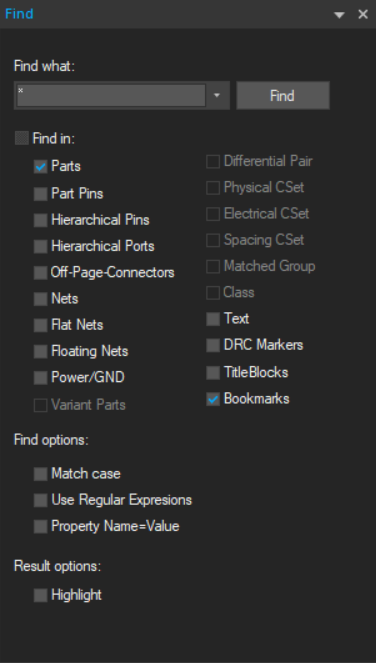
- In the search text box, enter a text string that defines the object you are searching. This could be the name, alias, or property value. You can use the standard "*" and "?" wildcard characters.
The Find pane contains search options that allow you to further refine your search. - From Find options, verify that the Match case option is set as required.
- From the search options drop-down list select the object type.
- Press Enter or click the Find button.
The Find Results window displays a list of objects that meet the criteria you specified. - If you want to display an object, double-click the entry in the Find Results window. The schematic page editor opens and the object appears in the selection color.
OR
If you want to edit the properties of one or more listed objects, from the Edit menu choose the Properties command - to display the spreadsheet editor.
ALSO
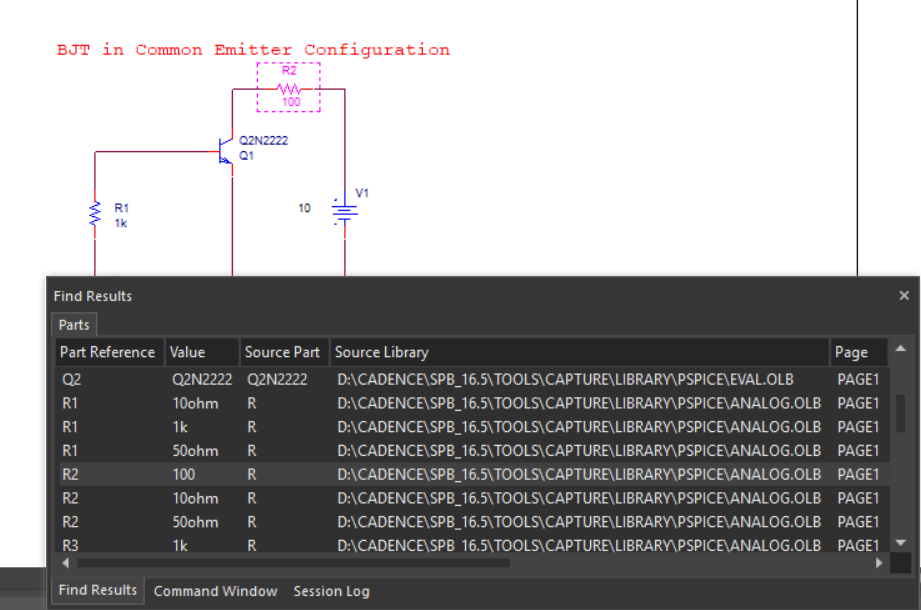
If you want to open the Browse Spreadsheet for a part in the Find Results window, right-click the part and choose Edit Properties. The Browse Spreadsheet dialog box opens.
Searching in Capture
In Capture, you can search for specific comment text on a part, or you can search for a pin by name or by one of its property values.
Locating an Object in a Project
Using the Find command and a part property value, you can locate a part in a schematic folder or on a schematic page. In the Find pane, you enter a property value string and specify that you want to find a part. Capture searches all the parts to find those with a property value that matches the string. You can use question marks (?) or asterisks (*) as wildcards in the property value string.
To locate an object in a project, do the following:
-
In the project manager, select the schematic folders or schematic pages you want to search.
-
Choose Edit – Find, click the search icon (
 ), or press
 CTRL+F.The Find pane appears.
-
In the search text box, enter the property value string for the part you search. You can use wildcard characters (standard "*" or "?") with a truncated search. For example, to search for resistors, enter "R*".
You can also search for a part by property or use regular expressions in your search string.Note that with Regular Expressions search feature enabled, Find performs a complete match for a search string containing alpha-numeric characters, underscore (_) or space unlike the standard regular expression search in TCL. For any other characters or patterns in the search string, standard TCL regular expression search behavior is observed. -
The search options allows you to specify search criteria.
-
You can choose a case-sensitive or case-insensitive search.
-
You can highlight the first object found from the search.
-
You can choose the type (or types) of objects to search.
-
-
Click the Find button to start the search.
Object that have a property value matching the property value string in step 3 are displayed in the Find Results window.
-
Double-click the part in the Find Results window list to open the schematic page editor with that part displayed and selected.
-
To search for all parts with references containing R or C followed by any number between 2 and 9, use the search string Part Reference=(C|R)[2-9] with both Property Name=Value and Regular Expressions option selected.
-
To search for whole word of parts containing R or C followed by any number between 2 and 9, use search string \m(C|R)[2-9]\M or ^(C|R)[2-9]$ with Regular Expressions option selected.
Searching a Design Hierarchy
The find functionality in Capture allows you to search at different levels of the design hierarchy.
Design Level
-
In the project manager, right-click a design and choose Find.
-
In the Find what text box, type the search string and press
Enter.The search results displayed in the Find Results window include all objects found within the entire design.
Folder Level
-
In the project manager, right-click a folder and choose Find.
-
In the the Find what text box, type the search string and press
Enter.The search results displayed in the Find Results window include all objects found within the selected folder.
Page Level
-
In the project manager, right-click a schematic page and choose Find.
OR
Open the schematic page to search and choose Find from the Edit menu.
-
In the Find what text box, type the search string and press
Enter.The search results displayed in the Find Results window include all objects found on the selected page.
Multiple Object Selection
-
In the project manager, use the
CTRL + mouse clickcombination to select multiple objects.You can select multiple folder or multiple pages or any combination of folders and pages.
-
Right-click the selection and choose Find.
-
In the Find what text box, type the search string and press
Enter.The search results displayed in the Find Results window include all objects found within the selected items in the design hierarchy.
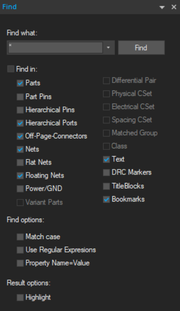
Find Pane
The find functionality in Capture is available through the Find pane.
|
Find what text box |
Enter the text to search. |
|
Find button |
Run the search command. |
|
Find in |
This is a multiple selection list. It contains the search options that you can set to narrow down or broaden your search. This includes all the searchable object types on your schematic. So if you want to search only for parts, ensure that all the other objects types are unselected. Since it is a multiple-select list, you can select multiple object types to search. |
Find Results Window
After the search is complete and if it returned at least one result, the result is displayed in the Find Resulst window. This is a tabbed dockable window.
Each result of the search will display as one line item in the window. A result line item contains other information besides the search object reference. This includes the page and schematic and properties specific to object types.
If the search returns multiple object types, each type displays in a different tab in the window.
If you double-click a line item in this window, the corresponding object is selected on the specific schematic page.
This window can be set as dockable or floating by double-clicking the title bar. In the docked mode, use the down-arrow button to change the window to Floating or Tabbed, or to hide it.
The pop-up menu on the Find Results window contains options as shown in the following figure:
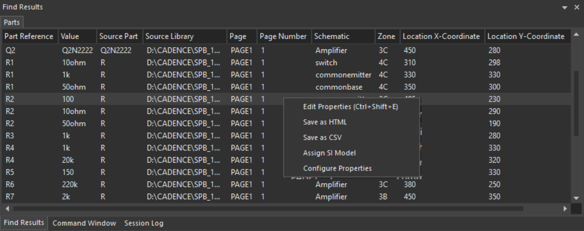
Edit Properties
You can open the Browse Spreadsheet window for a selected part in the Find Results window.
To do so:
- Right-click one or more results line items.
- Choose Edit Properties.
The Browse Spreadsheet window displays the editable part properties.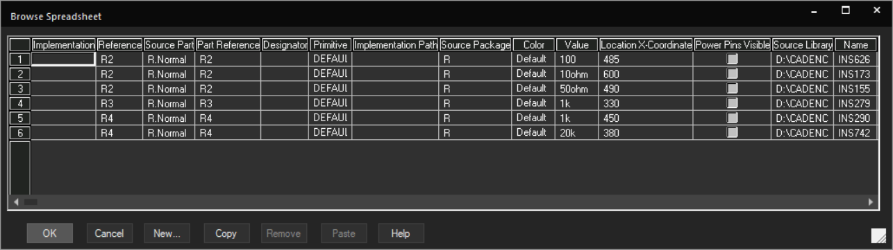
Save as HTML
You can also save your search results in the HTML format.
- Right-click a search results line item.
- Choose Save as HTML.
A message displays with the location and name of the exported HTML.
Save as CSV
You can also save your search results of the selected tab on the Find Results window in CSV format.
- Right-click a search result line item.
- Choose Save as CSV.
A message displays with the location and name of the exported CSV.
Renaming a Design
When you create a project, a design is created within the project. This design has the same name as the name of the project. However, you have the option to rename this design. Alternatively, you might have an existing design that you want to replicate and use as another design. Here too you can rename the design.
To rename a design
- In the Project manager, select the design (.DSN) file.
- From the File menu, choose Save As.
The Save As dialog box displays.
In this dialog, you specify an alternative name for the design.
You can also specify an alternative directory location for the design. - Enter a name for the design and click OK.
Saving and Closing a Design
Any changes you make to a design are temporary until you save the design.
When you save a design, you save only the changed schematic pages and folders in the design. The changed design as well as any edited pages are marked by the asterisk (*) character.
To save a design
- From the File menu choose Save.
To save a design to a different location
- From the File menu choose Save As.
- In the Save As dialog, choose the name and location for the design.
To close a design
- From the File menu choose Close.
Compare Designs
You can compare designs, schematic folders, schematic pages in Capture using the Design Differences dialog box. To access the Design Differences dialog box in Capture, select Tools - Compare Designs.
You can compare two designs, two individual schematic folders or All schematic folders, two individual schematic pages or All schematic pages.
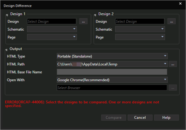
Using the Design Difference dialog box, you can generate either a lightweight HTML or a portable HTML to view the differences. The lightweight HTML requires the Cadence hierarchy on the machine. The portable HTML, which takes more space on the disk than the lightweight HTML, does not require the Cadence hierarchy and can be launched from any machine.
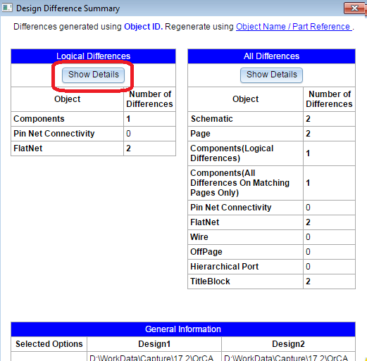
After you click Compare, you can view logical differences and all differences in the Design Difference Summary window. All differences consists of logical and graphical differences. To view details about differences, click the Show Details button in the Design Differences Summary window.
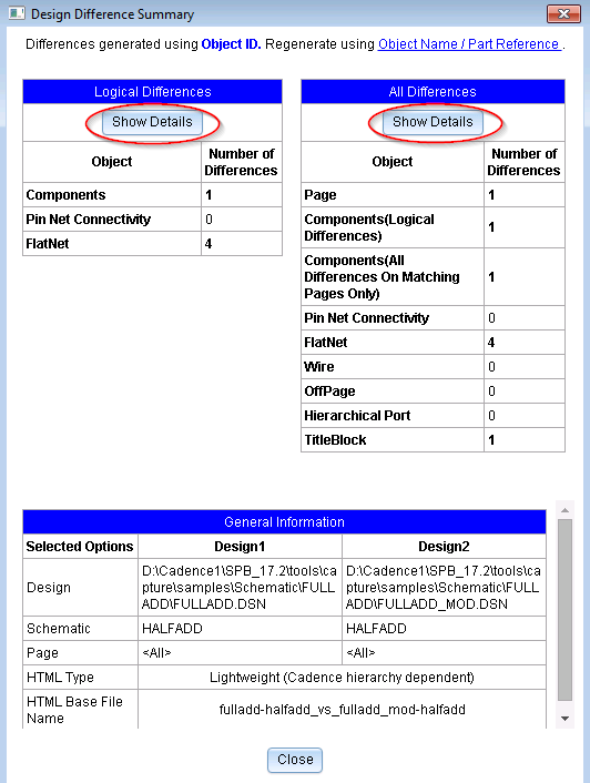
The following is an example of logical differences displayed in the HTML browser. In this example, two different part references are compared.
To view details about all differences, click the Show Details button in the All Differences table of the Design Difference Summary window.
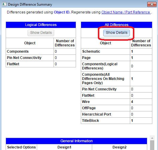
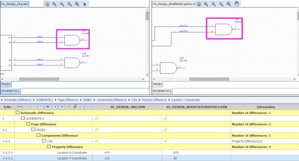
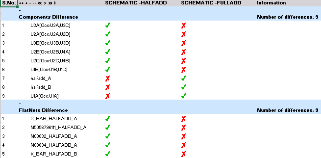
Following is an example of graphical differences displayed in the HTML browser. In this example, the part's location in the first design is different from the part's location in the second design.
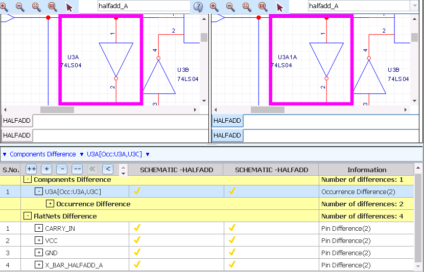
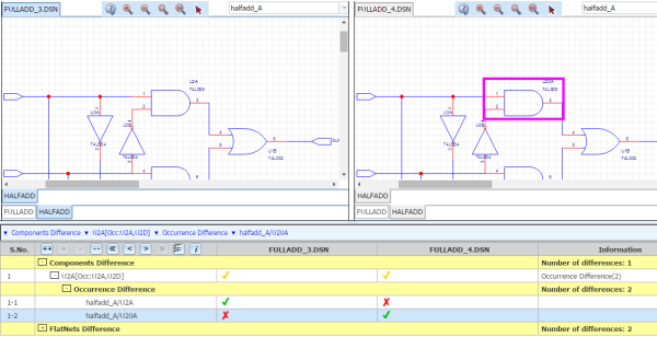
Using the Compare Design feature, you can verify if two designs are same part with different occurrence value.
Following is an example of logical differences displayed in the HTML browser. These logical differences display different occurrence values of the same part in two different design.
Importing Component Differences to Microsoft Excel and HTML
To export component differences found in the Compare Designs window for logical and all differences to a Microsoft Excelsheet, click on  in the generated Compare Design html file.
Following is an example of an excel export that illustrates exporting of component differences to an .xls file:
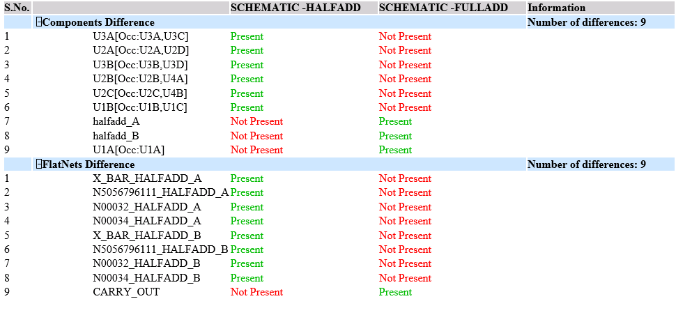
Similarly, to export component differences found in the Compare Designs window for logical and all differences to a HTML file, click on  in the generated Compare Designs html file.
Following is an example of an HTML export that illustrates exporting of component differences to a HTML file:
Exporting and Importing a Design from XML
To export a Capture design to the XML format, do the following:
- Open the required design in Capture.
- Select File – Export – Design XML.
The DSN To XML dialog box opens with the design file path already updated in the DSN File field. - Change the XML file name and location, if needed.
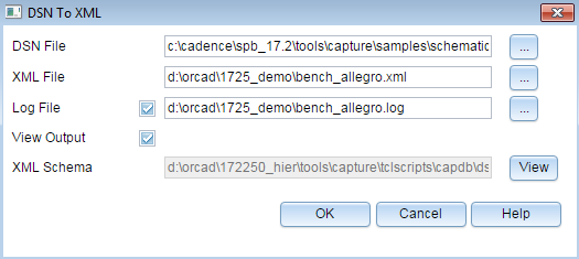
To convert the Capture design (.dsn) file to an XML file, Capture uses an XML schema that is located at the following path:<installation_directory>\tools\capture\tclscripts\capdb\dsn.xsd -
Click OK.
To import an XML to create a Capture design, do the following:
- Launch Capture.
- Select File – Import – Design XML.
The XML to DSN dialog box opens. -
Specify the input XML file path.
The DSN File field gets updated. -
Click the Browse button corresponding to the DSN File field if you want to save the generated design at a different location. This is optional.
- Select the Overwrite Mode from the drop-down list.
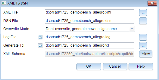
- Click Ok.
Reviewing Designs using Comments and Markups in OrCAD X Capture
OrCAD X Capture supports design review using comments and markups. You can mark any area in the design canvas using rectangular or arrow markups and add text comments in the Comments panel. Each comment is saved with a unique ID. A comment may have more than one markup associated with it. You can perform the below tasks.
Adding Comments and Markup in OrCAD X Capture
You can add comments when reviewing a design in OrCAD X Capture. To add a comment, perform the following steps:
- Choose the Markup option in the Tools menu. The Markup dialog box appears.
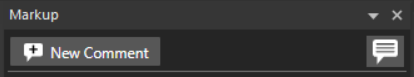
If the design already has comments, the panel displays prepopulated review comments from previous sessions.
- Click the New Comment button. A new comment card opens at the top, and existing comments are listed below.
The comment card displays the user name, user avatar, text field, markup tools, text formatting buttons, and options to save or discard a comment. Comment text can be formatted using rich text features such as bold, italic, and underline.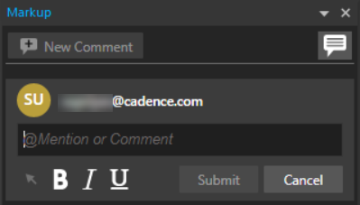 It also contains a markup tool that allows you to mark any area in the design canvas using a rectangle or arrow. This tool is a graphical annotation in the design canvas, highlighting the areas where comments are added.
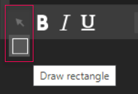
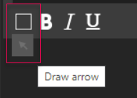
- Select the markup tool in the comment card to draw a rectangle to mark a rectangular-shaped area or an arrow to point to an object in the design canvas.
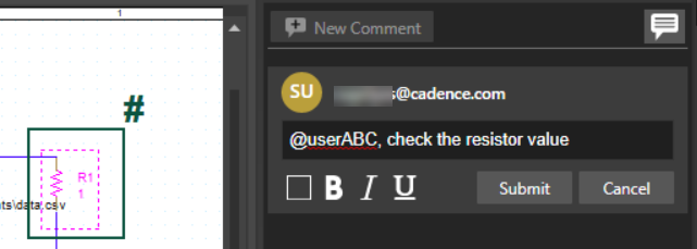
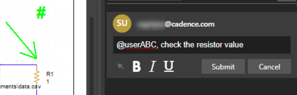
- Enter the comment in the text field, and press Submit.
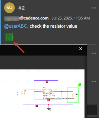
Once the comment is submitted, the markup data displays the information such as a unique comment ID, a timestamp displaying the local time zone, and a snapshot of the design (.dsn).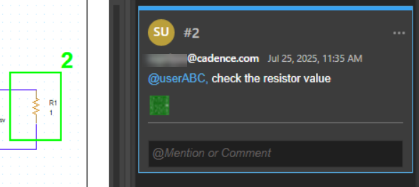
- You can click the snapshot as shown and see the information of the design:
-
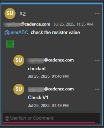
To respond to a comment, click the text field and add your reply.
 Even if the comments are in sync with the design, the design changes can go out of sync. To sync the design changes with the published comments, you need to manually sync the latest changes from the shared workspace to your local workspace (My Workspace).
 - You can also disable the markup visibility by clicking the Toggle Markup Visibility icon.
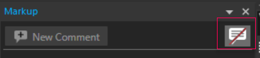 The highlighted markups are disabled in the design canvas.
Editing Comments and Markup in OrCAD X Capture
You can modify a review comment and markup using the following steps:
- From the list of comments in the Review panel, select a comment you want to modify.
- Click the More Options icon to choose options to edit, delete, or resolve a comment.
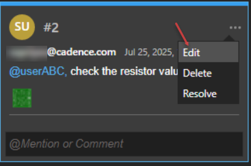
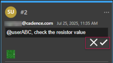
- To edit a comment, select an appropriate icon to save or discard the comment.
- To delete a comment, choose the Delete option from the drop-down menu.
- To resolve a comment, click Resolve to close an open comment.
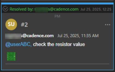
A reply can be added when marking it resolved, The resolved comment displays the status and the user name who resolved it. A comment, when resolved, removes its markup from the canvas. - You can also reopen a resolved comment. To do this, click Reopen.
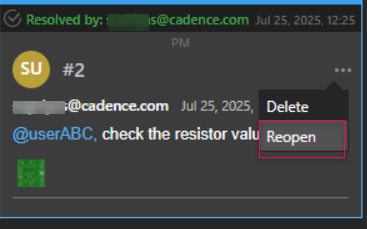 The markup is restored in the design canvas.
- To edit a comment, select an appropriate icon to save or discard the comment.
View the next document: 06 - Working with Schematic Folders
If you have any questions or comments about the OrCAD X platform, click on the link below.
Contact Us