05 - Setting Up the OrCAD X Presto Design Environment
When setting up the OrCDA X Presto layout design environment, specify grid size, adjust the color display and visibility of layers and objects required.
Setting Up Grids Setting Up Backup Preferences Controlling Visibility of Objects and Nets Controlling Visibility of Individual Objects Controlling Visibility of Objects and Layers Using Color View File Customizing Colors and Patterns of Design Objects Controlling Visibility in 3D Customizing Keyboard Shortcuts in OrCAD X Presto Setting up Local Language Preferences in OrCAD X Presto
Setting Up Grids
The PCB grid consists of intersecting horizontal and vertical lines, forming coordinates that help component placement and routing on the layout. Using the appropriate grid resolution for component placement and routing helps organize components to align with each other and create tidy traces during routing.
To set up grids in OrCAD X Presto, do the following:
 Click the icon from the top-left corner of the design canvas to view the Grids widget.
  The Grids widget provides options for selecting the x and y values for conductor and nonconductor grids in a design. You can also customize the grid by entering the grid values. The widget displays grid values in Mils, MM, and Microns. The default increment setting for non-conductor layers is x=100, y=100. For conductor layers, it is x=25, y=25.
- Click the On button in the Visibility section to enable grids.
- Select any predefined grid value. The modified grid values are applied globally and used for subsequent routing or placement operations. However, this change does not affect placed components and existing connections and vias.
- Alternatively, specify the x and y grid points in the Quick Grid section. You can choose the non-uniform spacing between lines by entering different x and y values.
You can either set a global grid for all components or separate grids for different types of components. Similarly, you can use a separate grid for each conductor layer in a design.
Setting Up Backup Preferences
OrCAD X Presto keeps design files safe by saving them automatically at regular intervals. The auto backup option is enabled by default and saves multiple revisions periodically in the working design directory.
To modify auto backup preferences, do the following:
- Choose Edit – Preferences. The Preferences dialog box opens.
- Select the Auto Backup page under the General category in the Preferences dialog box.
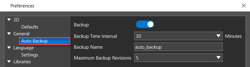
- Specify the Backup Time Interval between 5 minutes to 360 minutes or choose a value from the list. The auto backup is performed once the specified time is reached.
- Modify the Backup Name or use the default name.
- Specify the Maximum Backup Revisions between 1 and 10 or choose a value from the list. This value determines the number of backups stored. If the backup revision is set to 3, three versions auto_backup.brd, auto_backup.brd,1, and auto_backup.brd,2 are available in the working directory at a time. Other versions are overwritten.
- Click OK to apply the changes.
The configured settings are saved in the home directory.
Controlling Visibility of Objects and Nets
The Visibility panel allows you to modify the visibility of all design objects and layers to customize the design environment that suits your viewing requirements in 2D and 3D. You can modify the visibility of individual layers, objects, and geometries, opacity and transparency, display labels for nets, pins, and vias, and color for highlighting, drills, and connections of the complete design.
To modify the visibility of design objects, do the following:
- Open the Layers tab in the Visibility panel. This tab controls the displays of all the layer types, objects, and components for the selected stack-up.
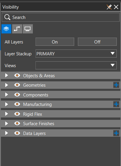
- To toggle the visibility of objects of the same type, click the header-level visibility icon of the collapsible sub-sections, such as Objects & Areas, Geometries, Manufacturing, or Data Layers.
- To toggle the visibility of individual objects, expand the group and click the visibility icon
 associated with that object.
- Open the Nets tab. This tab controls the displays of all the groups of nets and individual nets. Modify the visibility of nets as stated in the following steps:
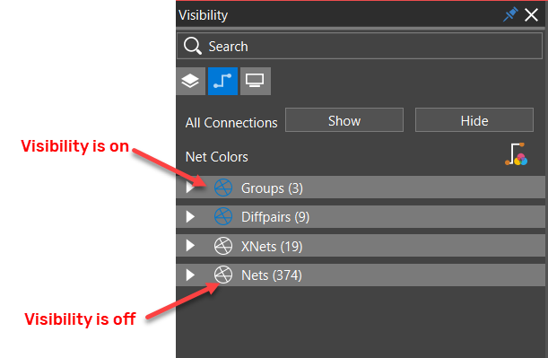
- Click the Connection Status icon to modify the visibility of any group of nets or a single net. The following image displays the visibility state of different types of net in a design:
- Click the Custom Colors On icon to view all the visible nets of a design in their assigned custom colors and patterns.
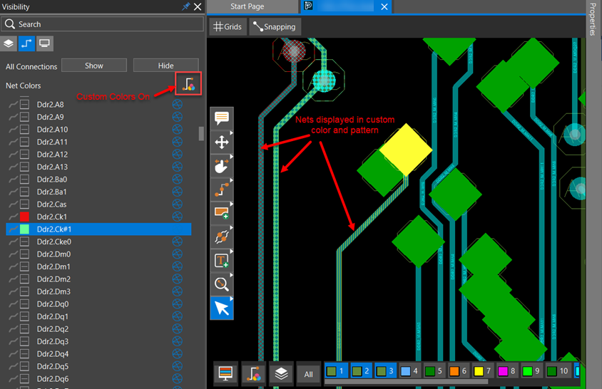
By default, custom colors are off and nets are displayed in layer colors.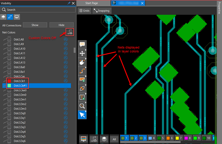 The Custom Color On toggle is also available in the floating layer toolbar.
Controlling Visibility of Individual Objects
The Visibility panel and the floating layer toolbar provide controls to enable or disable the visibility of any object for any layer. 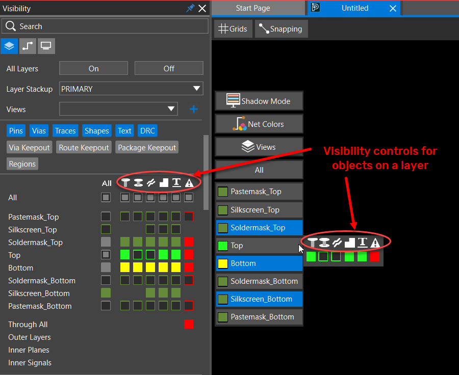
Controlling Visibility of Objects From the Visibility Panel
To modify the visibility of any object on any layer, do the following:
- Expand the Objects & Areas pane. This number of layers and objects displayed under this group depends on the layers and object types enabled in the filter section.
- Click the color toggle box to change the visibility of an object on a layer.
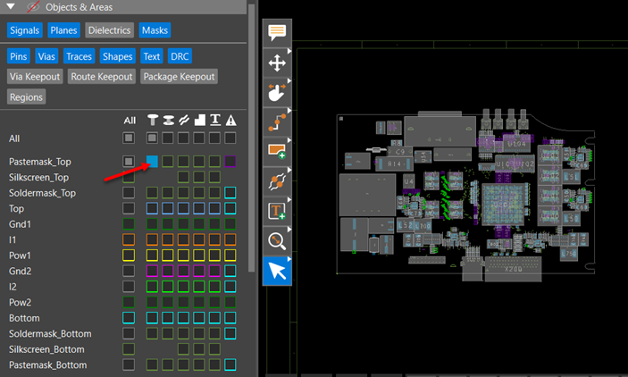
- To toggle the visibility of an individual object on a single layer, click the hollow box with a colored outline under the object type column and the layer row in the grid view. For example, to turn on the visibility of Pins on the TOP layer, text on the POW2 layer and DRCs on the BOTTOM layer, select the hollow color boxes as illustrated in the following snapshot.
 The solid color box indicates that the pins are visible on the TOP layer, the text is visible on the POW2 layer and the DRCs are visible on the BOTTOM layer.
 - To toggle the visibility of an individual object on all the layers, click the hollow box with a gray outline under the object type icon. For example, select the hollow box with a gray outline to enable the visibility of Pins on all layers, as illustrated in the following image:
 The solid gray box under the Pins object type icon indicates that pins are visible on all layers. Solid color boxes of different or the same color are displayed under the Pins object type column, indicating that the pins are visible for all layers.
 - To toggle the visibility of all the objects on all layers, click the hollow box with a gray outline under All in the grid view.
 The header visibility icon toggles. The solid gray boxes under object type icons indicate that the object is visible on all layers. Similarly, the solid gray boxes in front of the layers show that all the objects are visible on that layer.
 - To change the visibility of a single object at a time, press and hold the Alt key and click the color box in the grid view. In the following image, only pins on the TOP layer are displayed in the design. The visibility is turned off for the pins on the remaining layers. The rest of the objects are also not displayed at all.
Controlling Visibility of Objects From Layer Toolbar
To modify the visibility of an object from the layer toolbar, do the following:
- Right-click a layer to view the shortcut menu.
- Click the color toggle box to change the visibility state of individual objects on that layer.
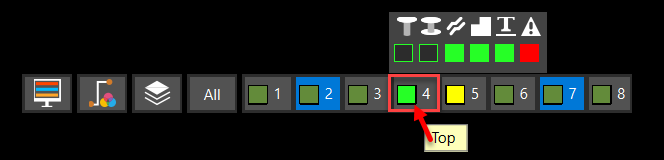
- Alternatively, click the All button to change the visibility of specific objects for each layer.
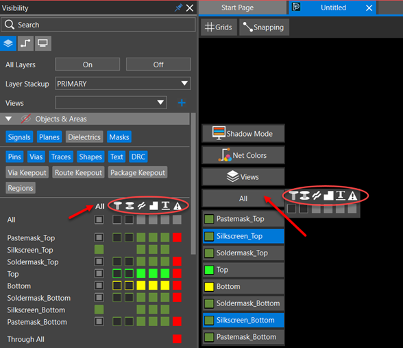
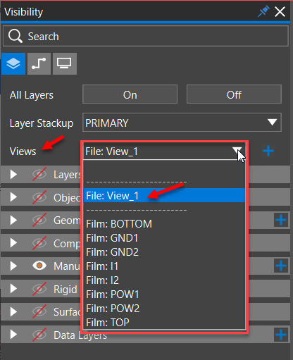
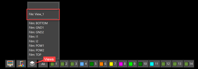
- Optionally, click the Views icon to select an existing view. A list of films generated from the artwork is displayed.
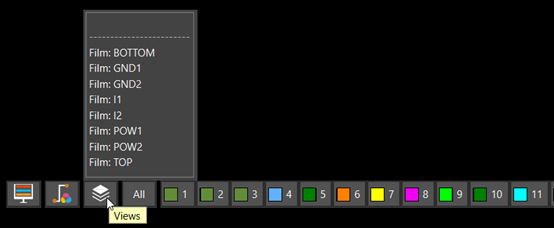 Depending on the selected view, the visibility of objects is dynamically updated for the objects on each layer.
Controlling Visibility of Objects From Command Window
To modify the visibility of any object on any layer from a command widget, do the following:
- Click the icon in the command toolbar to open the command widget.
- Toggle the visibility icon for the Layer field.
The visibility settings for the object (pin, via, trace, shape, or text) change in the Objects & Areas pane of the Visibility panel for conductor layers.
Controlling Visibility of Objects While Drawing
When using interactive commands, such as Add Connect, Add Line, Add Text, and Add Shape, you can see the pin, via, trace, shape, and text objects while drawing without manually toggling their visibility setting in the Visibility panel. A visibility toggle associated with the layer pulldown in the command window controls the visibility of objects on layers. By default, the visibility toggle matches the object visibility settings in the Visibility panel. If the visibility toggle is enabled, the drawing objects start to display in the design canvas, and their visibility settings also change in the Visibility panel. Depending on the active command, visibility changes for pins, vias, shapes, traces, and text are reflected through the color boxes in the Visibility panel. For example, when you invoke the Add Connect command, the layervisibility toggles reflect the current Visibility panel settings for pins, vias, traces, and shapes. In the following image, toggling the visibility of the Top and Inner2 layers changes the visibility of pin, via, shape, and trace objects in the Objects & Areas pane for those layers: 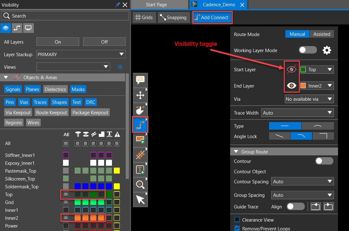 Similarly, in the Add text command, the visibility toggle shows the current Visibility panel settings for text objects on that layer. Using the visibility toggle, you can view the text while adding it, as well as show or hide texts in the design canvas on the selected layer. The visibility setting of the relevant layer also changes in the Visibility panel, as shown in the following image for Stackup_figure layer:
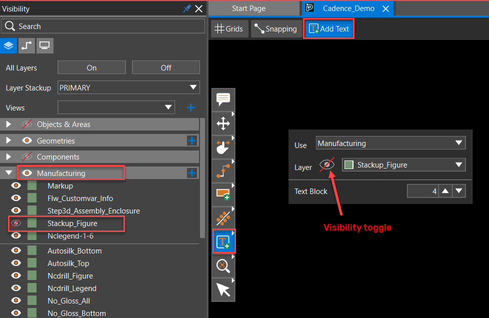
Controlling Visibility of Objects and Layers Using Color View File
A color view is a collection of visibility settings of objects and layers set in the Visibility panel. Color views make it simple to change the display in the design canvas. You can create a color view in the Visibility panel. The color view file, is a text file, saved with .color extension in the current design file directory. To apply a color view, use the Views drop-down list in the Visibility panel or the Layer toolbar.
Creating Color View
To create a color view, do the following:
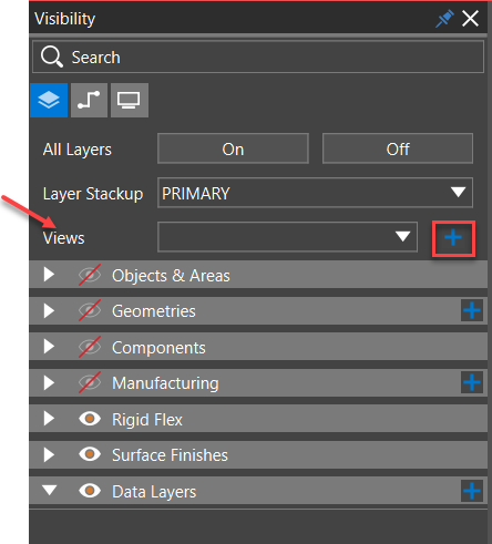
- Open the Layers tab in the Visibility panel.
- Click the plus button in the Views field. The save view widget opens.
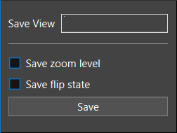
- Specify the name of the color view file in the Save View field.
- Select the Save zoom level check box to preserve the current zoom points. By default, it is off.
- Select the Save flip state check box to save the current state of the design. The flip state is true is the design is flipped along the Y-axis. By default, it is off.
- Click Save.
A view file (.color) is saved in the current design file directory.
Applying Color Views
To apply an existing color view settings, do the following:
- Expand the Views drop-down list in the Visibility panel or right-click the Views menu in the layer toolbar. The color views saved with the design are displayed at the top of the list.
- Select the view name. The current visibility settings of a design are replaced with the visibility settings saved in the selected color view file.
Customizing Colors and Patterns of Design Objects
The color settings for any design object, whether a layer, net, component, or design geometry, can be changed from the Visibility panel and the layer toolbar. Each object in the design has a small color button that displays its default color. Modifying color and stipple patterns helps identify critical objects in the design, especially shapes. Different objects on the same layer can have different stipple patterns attached to them. To modify the color and patterns of any object from the Visibility panel or the layer toolbar, do the following:
- Right-click the color box to open the color selector dialog box.
- Choose a different color from the Presets section or use the slider of the vertical color bar first to select a base color and then move the cursor in the color palette to choose the brighter or darker shade.
The current and new colors are displayed in the color box to preview the selection. The new color is applied to the color box of that object and the object color in the design canvas.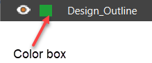
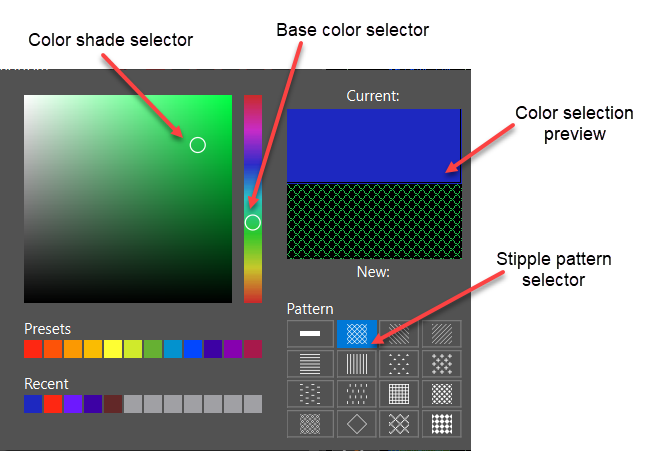
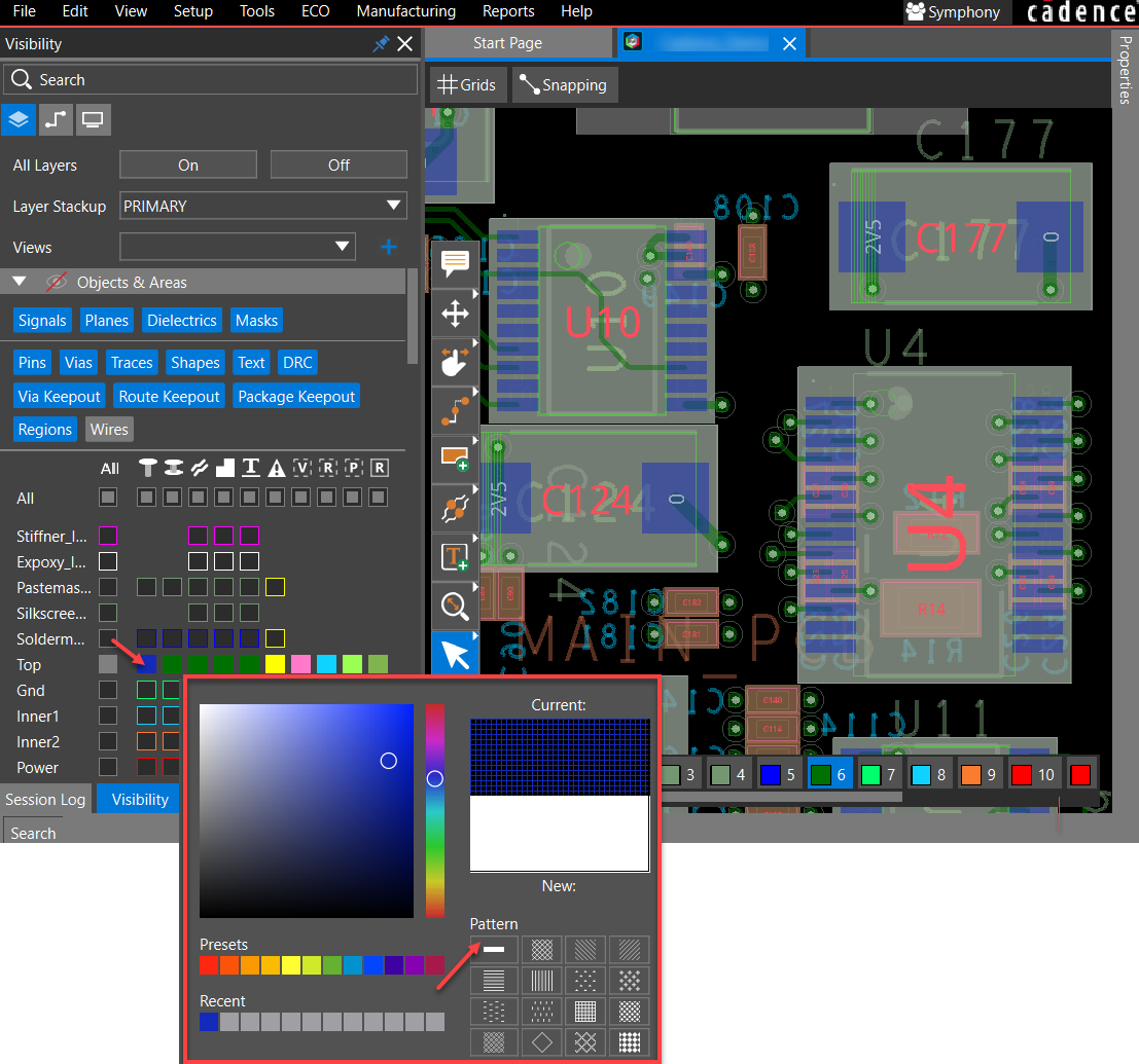
- Select a stipple pattern to apply to the object.
The respective layer or the object is highlighted with the selected stipple pattern.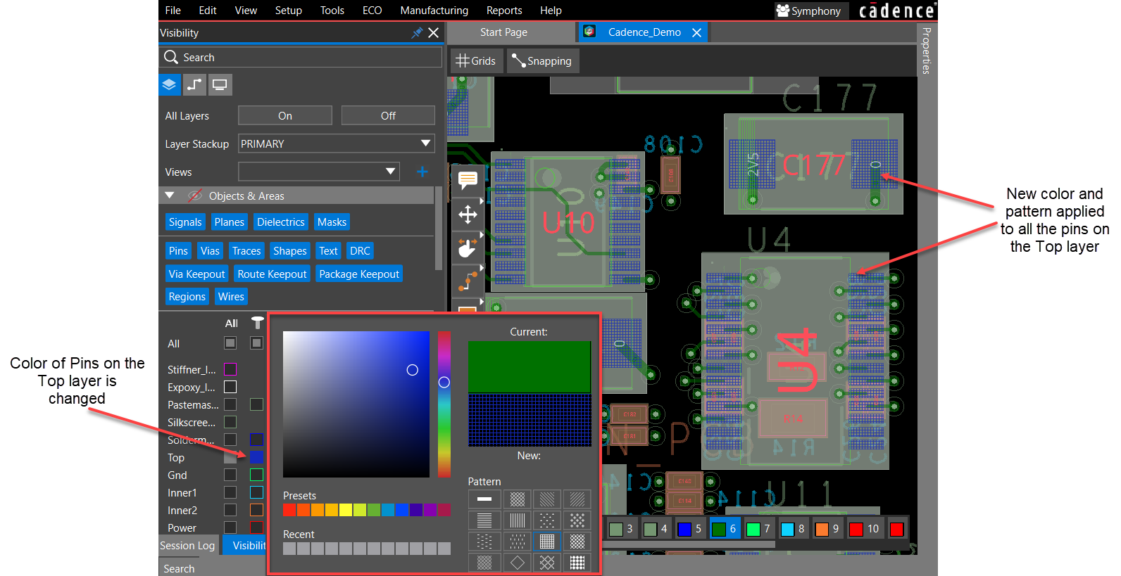
- Click anywhere outside to close the color selector dialog box.
- Right-click the color box and choose the first stipple pattern option (the plain white box). The highlighted layer or object returns to its default state (the solid color).
- Repeat steps 1 to 4 to apply different colors and stipple patterns to different objects on the same layer.
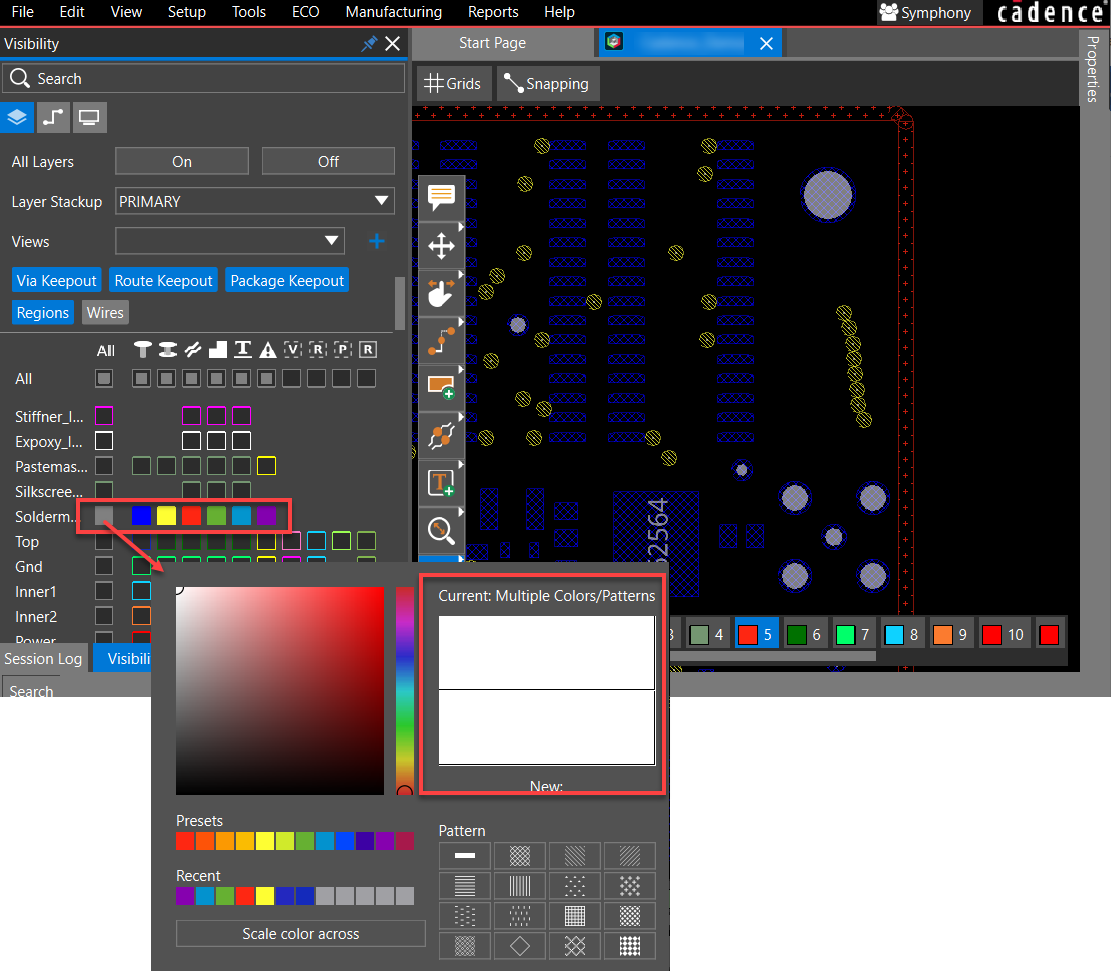
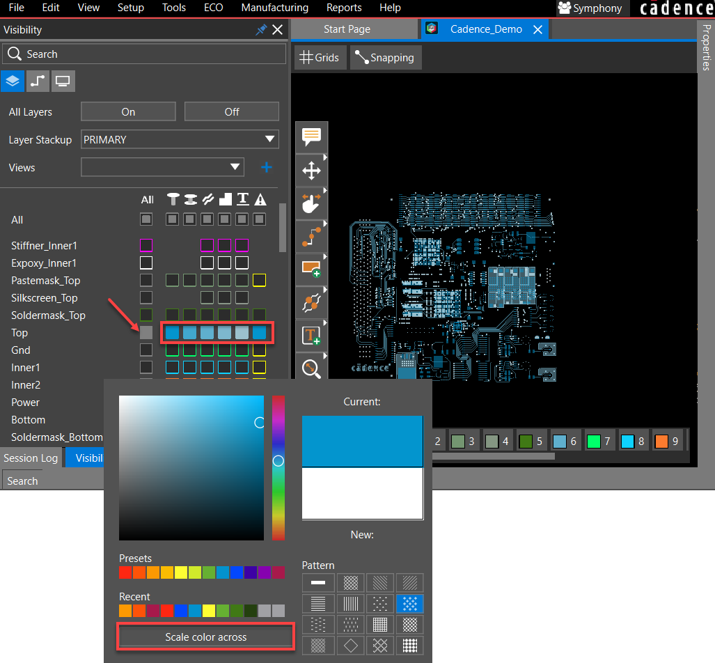
- Select the color box for All objects of a layer in the Objects & Areas pane. Select a new color and click Scale color across. The selected color is applied to different objects on that layer while varying the grey scale aspect.
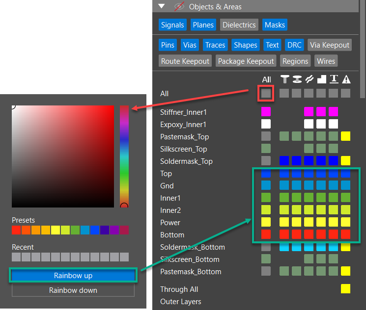
- Select the color box of the All column in the Objects & Areas pane and click Rainbow up. This option applies blue and red colors to the top and bottom signal layers, respectively, and fills the remaining signal and plane layers with the Preset colors, starting with the second layer from the bottom and going up to the top. This pattern is repeated until no layers are left. The color of the mask layers remains unchanged.
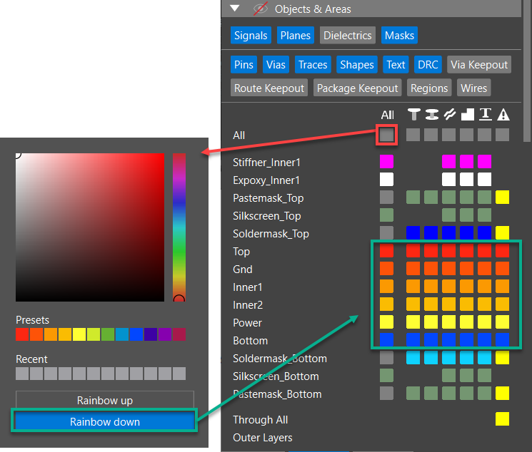
- Alternatively, select the color box of the All column in the Objects & Areas pane and click Rainbow down. This option applies red and blue colors to the top and bottom signal layers, respectively, and fills the internal signal and plane layers with the Preset colors starting from the second layer from the top and going down. This pattern is repeated until no layers are left.
- Apply color and patterns to an individual net or a group of nets using the following steps:
- Open the Nets tab in the Visibility panel.
- Click the color box of a net.
The color selector dialog box opens. - Choose a new color in the color selector dialog box. Also, select a stipple pattern in the
Pattern section. The new color is displayed in the net color box. The net color and pattern are also changed in the design canvas.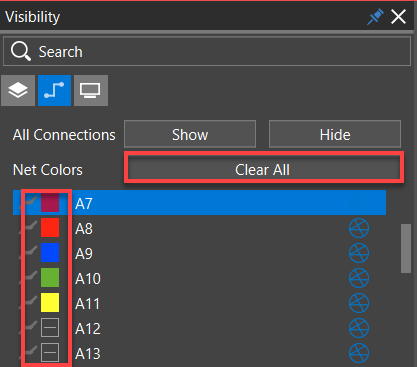
- Click Clear All to remove color assignments for all nets in the design.
Customizing Color and Pattern of Nets in the Properties Panel
The attributes of a net, including its color, are displayed in the Properties panel and can be modified there. To change the color of a net in the Properties panel, do the following:
- Open a design and navigate to the Properties panel.
- Select only Nets in the Selection Filter in the Properties panel.
- Click to select a net in the design canvas.
The net color is displayed in the General section.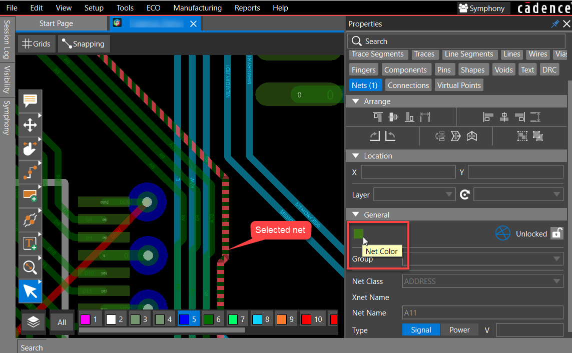
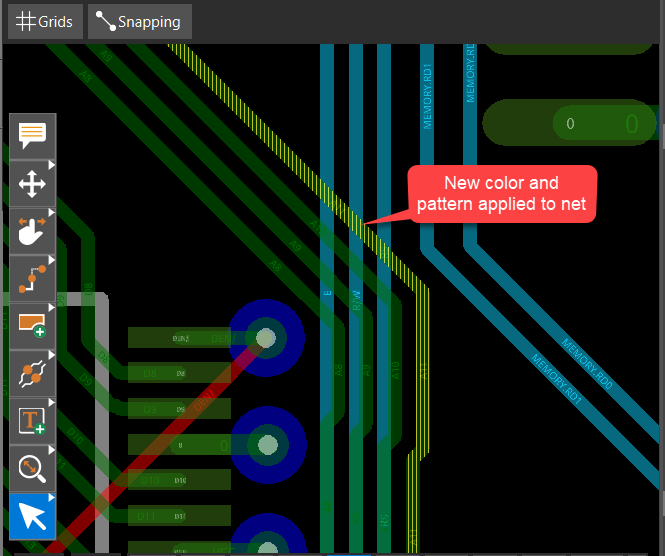
- Click the color box and choose a color from the Presets section, or use the slider of the vertical color bar first to select a base color and then move the cursor in the color palette to choose the brighter or darker shade in the color selector dialog box. Select a stipple pattern to attach to the selected net in the Pattern section.
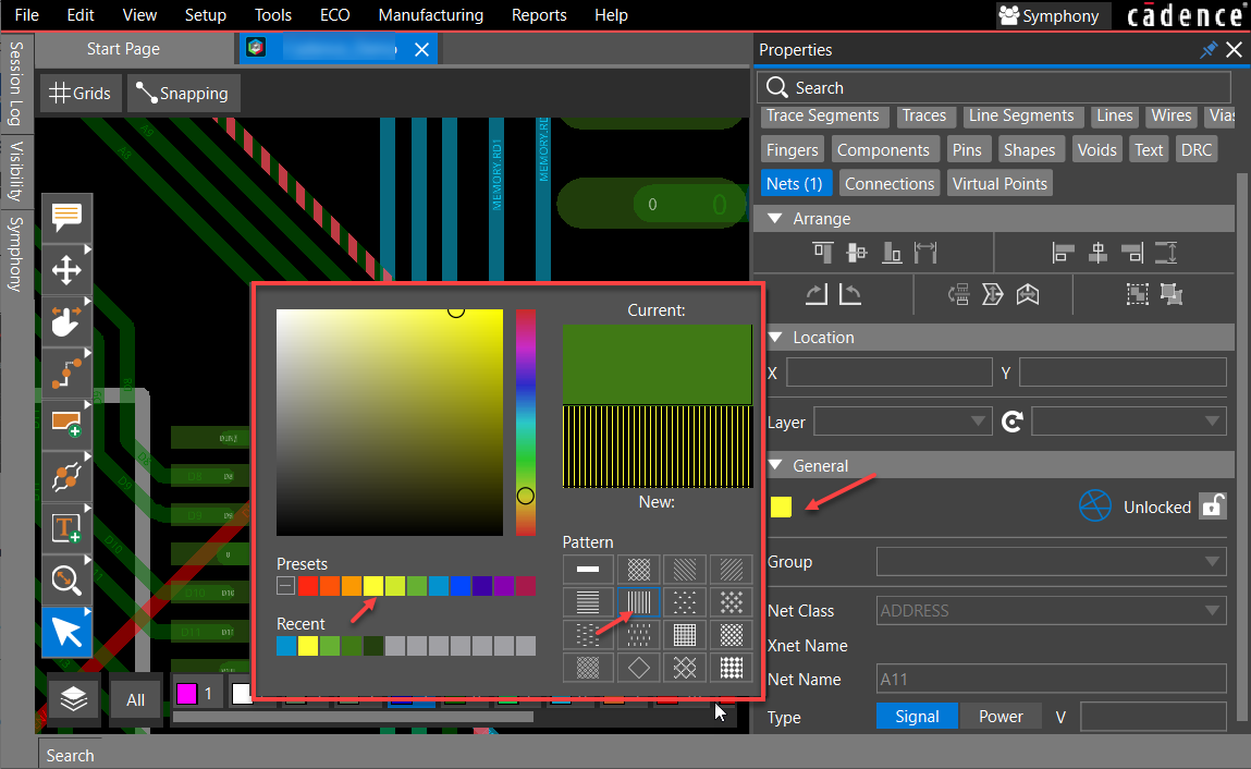
- Click outside the color selector dialog box to apply the changes.
- Select multiple nets using the Ctrl key or by drawing a rectangle to window select them.
- Repeat steps 3 to 5 to change the color and stipple pattern of multiple nets.
If the selected nets have different colors assigned to them, the net color box displays a rainbow in the Properties panel.
Controlling Visibility in 3D
To set up visibility of objects and layers in 3D, do the following:
- Open the General tab of the Visibility panel and choose 3D mode. The Visibility panel displays settings for viewing a design in 3D and the canvas switches to 3D. Components placed on the TOP and BOTTOM layers along with mechanical components are displayed in 3D.
- Use the Camera icon,
 placed at the bottom-right of the design canvas, to view 3D graphical data in different perspectives.
- Select the Perspective projection type to view the design as if you are standing above the center of the assembled board. Objects that are far away appear smaller than those are near. This option is selected by default.
 Alternatively, select the Orthographic projection type to view the design as if you are standing directly over each object of the board. In this view, all of the objects appear the same size.
- In the layer toolbar, click any layer to turn on or off its visibility in the 3D design canvas.
- Adjust the slider or specify a value to set the transparency of 3D objects in the 3D Opacity section.
- You can set the opacity value between transparent (25%) and opaque (100%).
- To choose components for displaying in 3D, do the following:
- Open the Components tab that is added to the Visibility panel in the 3D mode.
- Select 3D Bodies as Model, Place, or DFA.
The following image illustrates how a design look when different types of 3D bodies are selected:
- Expand the groups Top, Bottom, and Mechanical to view a list of components placed on these layers.
- Select a component from the list and click the visibility icon to toggle its visibility.
- Repeat the above step to modify the visibility of individual components.
Alternatively, use the header-level visibility icon to disable the visibility of all the components under that group.
Customizing Keyboard Shortcuts in OrCAD X Presto
Shortcut keys make navigation and execution of frequently-used commands easy. OrCAD X Presto provides quick access to interface-based commands and navigation controls using standard shortcut keys. You can view the currently assigned shortcut keys in the Preferences dialog box. Additionally, you can assign or remove keyboard shortcuts to any command or display control in OrCAD X Presto using the following steps:
- Choose Edit – Preferences. The Preferences dialog box opens.
- Open the Shortcuts (Hotkeys) page to view the default shortcut keys assignment. A table displays the icon, name, and default shortcut key assignments.
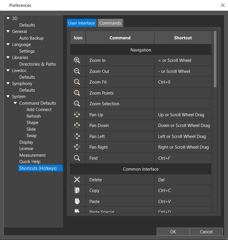
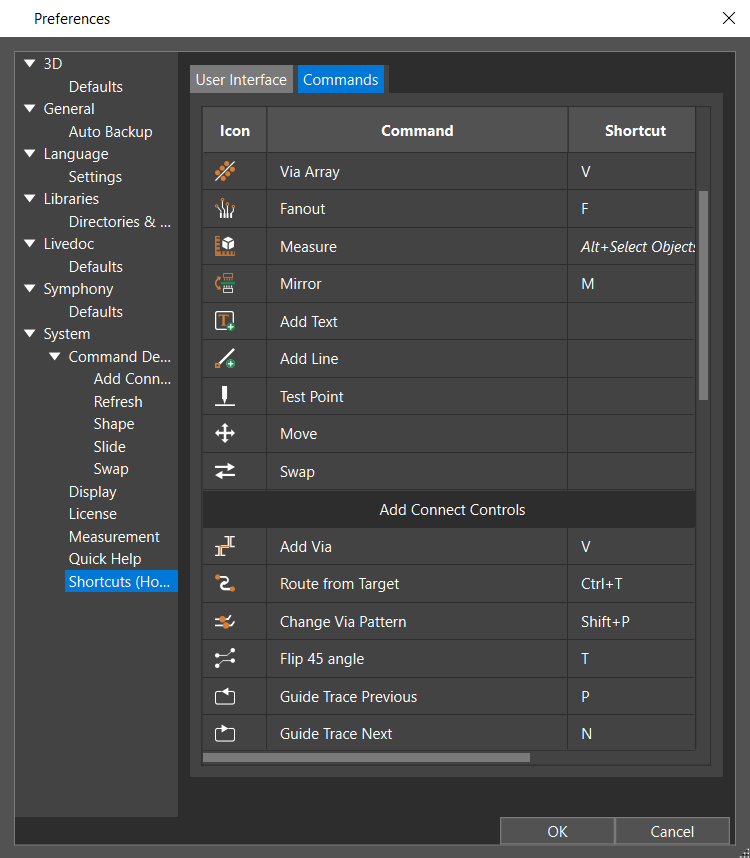
- Double-click the shortcut cell in the table to change or add a new shortcut key. The selection is highlighted in blue.
- Press the key or the combination of keys that you want to assign. The new key is displayed in bold to indicate it as an overridden value. A Reset button also starts displaying.

- Press the Reset button to restore the default shortcut key.
- Double-click the shortcut key and press the Delete button to remove the shortcut key.
- Click OK in the Preferences dialog box.
Setting up Local Language Preferences in OrCAD X Presto
The layout editor environment can be configured in the local language. The language preference settings, when selected, override the default font and display all menus, dialog boxes, and windows showing text in the regional language font. The local language support is available only for Chinese and Japanese languages. The language settings applied to the layout editor are inherited by its utilities, such as Constraint Manager and Padstack Editor.
The data written to the database or saved in a file is not affected by this setting and remains in the default English language. For example, the names of database objects, such as nets, layers, and design units, continue to display in English.
To view the layout editor user interface in the local language, do the following:
- Choose Edit – Preferences.
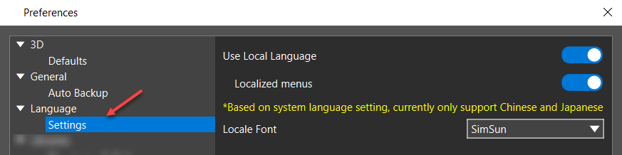
The Preferences dialog box opens. - Select Settings in the Language category.
- Select the Use Local Languagecheckbox.
- Select the Localized Menus checkbox.
- Specify the Locale Font from the pull-down list.
- Close the layout editor.
- Modify system language (system locale).
- Choose either Chinese or Japanese as a regional format.
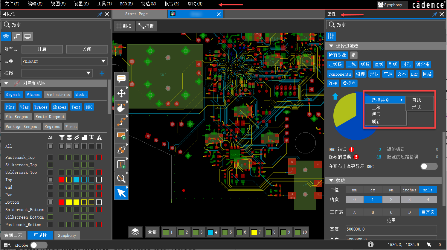
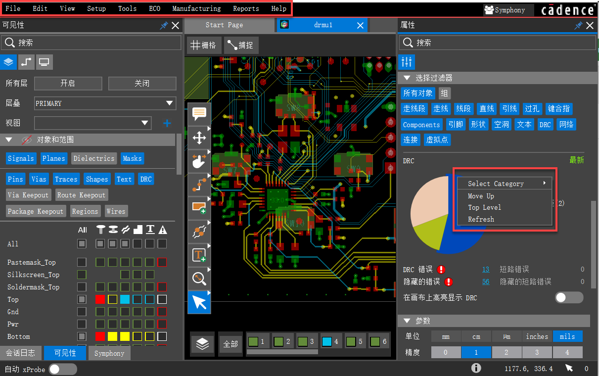
- Restart the layout editor. All the text displayed in the user interface, such as menus, dialog boxes, messages, and datatips, starts displaying in the selected language. The following image displays user interface text in the Chinese language font.
- Choose Tools – Constraint Manager. The Constraint Manager user interface displays all the text in the regional language.
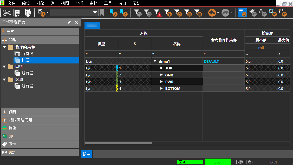
- Close the Constraint Manager window.
- Reopen the Preferences dialog box.
- Deselect the Localized menus checkbox and exit the layout editor.
- Restart the layout editor. The menus are displayed in the default English language. Rest all other text is displayed in the selected local language.
View the next document: 06 - Editing Design Objects in OrCAD X Presto
If you have any questions or comments about the OrCAD X platform, click on the link below.
Contact Us