06 - Editing Design Objects in OrCAD X Presto
OrCAD X Presto provides efficient editing capabilities for layout designs. Objects can be edited during or after placement. Editing objects allows for iterative improvement in the design and ensures that the final product meets the required specifications and quality.
Copying Objects
OrCAD X Presto provides the Paste Special command to copy design objects across the layers of the PCB design. Specifying a destination layer when copying traces and shapes speeds up the design time by leveraging the same shape and etch patterns on additional layers.
The Paste Special command also provides the capability to specify a different shape when pasting the copied shape object. It helps create constraint regions or keepout areas based on existing shape geometry. You can also exclude existing manual voids in the copied shapes during the paste operation if these voids are not needed on destination layers.
To paste objects using the paste special command, do the following:
- Set the Selection Filter in the Properties panel.
- Copy objects in the design canvas.
- Choose Edit – Paste Special or right-click and choose Paste Special.
The Paste Special widget opens and displays relevant fields if valid objects are copied and saved in the paste buffer. Valid objects include shapes (Etch, Keepout, Constraint Region, Keepin), traces, trace segments, and lines. A pre-paste view of the objects is attached to the cursor that reflects the current settings in the Paste Special widget. The bottom part of the widget displays the status of the command and includes the number of objects available for paste, a warning or error symbol, and a visual cue on the cursor. The status changes dynamically based on the objects copied and widget settings. Hovering the cursor over the warning or error symbol displays more information on the tool tip text.
A warning is indicated by a yellow triangle and displayed when only one object qualifies for paste from the copy buffer. An error is displayed as a red triangle when none of the objects being copied are available for paste. In case of the error, the cursor changes to red circle with slash (the universal no sign) as a visual cue to indicate that paste operation cannot be performed.
- Choose a design layer from the Destination Layer setting as required. The Destination Layer field lists all design layers. The default value of this field changes in context with the copied objects and the Shape Use settings as follows:
- Modify the Shape Use setting to specify the shape of the pasted shape objects.
This option is available only when a shape is copied. No paste operation is performed if multiple shapes exist in the copy buffer, and none are valid for the shape type set as the Shape Use setting. - Exclude or retain manual voids using the Retain Manual Voids check box if a shape is selected with voids.
- Enable the destination objects in the Selection Filter in the Properties panel.
- Click the design canvas or window select multiple objects to select a destination. The objects are pasted to the original location of the copied objects.
Moving Objects
OrCAD X Presto offers various methods for relocating objects within a design, allowing for optimization of the design for placement and routing.
- Moving Objects Using Shortcut Keys
- Moving Objects from Properties or Search Panels
- Moving Objects Using Move Command
Moving Objects Using Shortcut Keys
To move single or multiple objects in a design using shortcut keys, perform the following steps.
- Click in the design canvas to select an object or draw a window to select a group of objects. The objects are highlighted. The origin of the move operation is the snap pick location of the single or multiple objects.
- Move the selected objects using shortcut keys in the following ways:
- Press
A, D, W,orZto move an object in the left, right, up, or down directions, respectively.
The object moves by one grid point relative to the last location of the object. - Pressing
Shiftwith shortcut keys.
The object moves by ten grid points relative to the last location of the object.
- Press
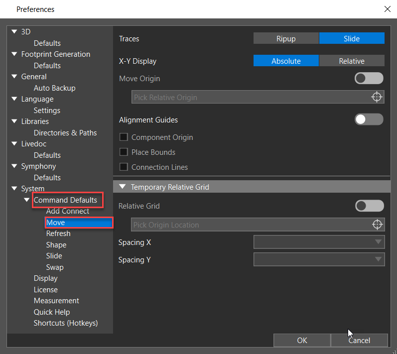
- Optionally, choose Edit – Preferences to modify the move command defaults or the shortcut keys.
Arrow keys, by default, are assigned for panning operations. You can, however, override panning preferences and assign arrow keys as shortcut keys for move operations.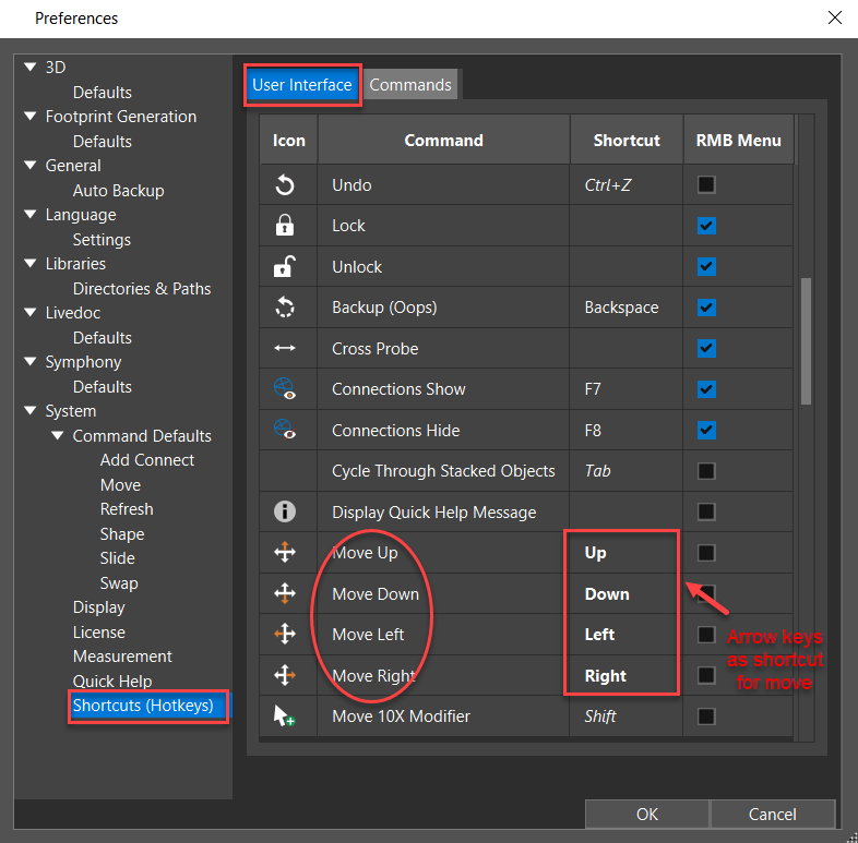
Moving Objects from Properties or Search Panels
When moving objects, you can leverage the location fields of the Properties or Search panels without invoking the move command. To move an object in the X or Y direction, do the following steps:
- Select an object or window select a group of objects in the design canvas. The layout editor highlights the selected object.
- Double-click the location fields to edit the values of:
- X or Y cells in the Location pane of the Properties panel.
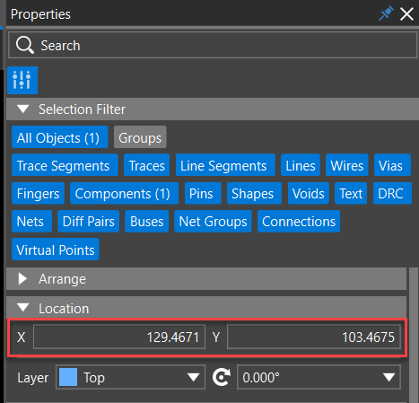
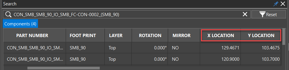
- X LOCATION or Y LOCATION cells of the Search panel.
- X or Y cells in the Location pane of the Properties panel.
- Enter the location value in the following two ways and press Enter.
- Type an absolute value without any modifier symbol (+ or -), such as 139.
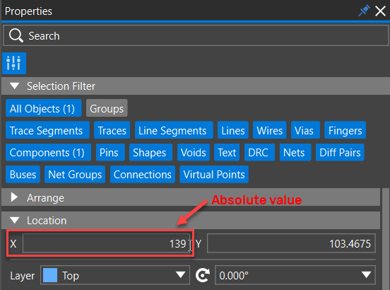 The layout editor considers the new location value as absolute and moves the object to its new location.
 - Type an incremental value with a + or - modifier symbol, such as -10 or +10.
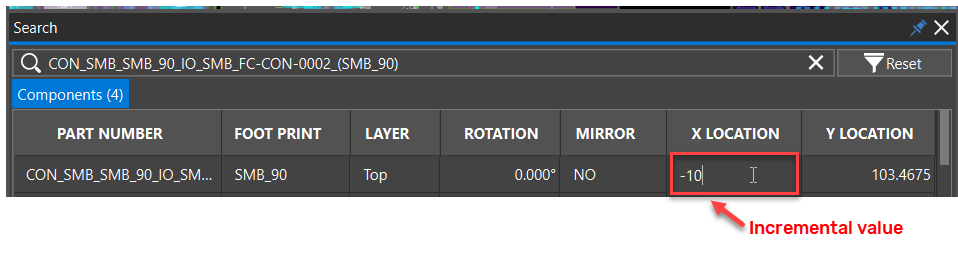 The layout editor considers the new location value as incremental and moves the object to its new location.
- Type an absolute value without any modifier symbol (+ or -), such as 139.
Moving Objects Using Move Command
To move a single or multiple objects using the Move command, perform the following steps. You must have OrCAD X Professional and higher licenses to access the move command.
- Choose the Move icon in the command toolbar.
The move command window opens, displaying default options set in the Preferences dialog box.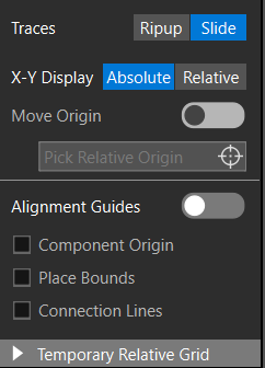
To show and hide move command options, press the shortcut key X. You can also dock the move command window as a panel by selecting the Dock as Panel option in the Command Defaults of the Preferences dialog box.
- Click in the design canvas to select a single object.
The object attaches to the cursor. The snap pick location is considered the origin of the move operation. The traces or ratsnest lines attached to the objects become dynamic rubber band lines. - Alternatively, drag the cursor to draw a window to select multiple objects. Click again to pick the origin for the move operation.
- Move the object to pick a new location.
As you move, the absolute value of the X and Y coordinates of the original pick point and the new select point is displayed. A crosshair is also displayed at the new select point, and a dashed line connects it to the original pick point. By default, any traces attached to the object move in Slide etch mode. When multiple objects are selected, the slide etch option is ignored.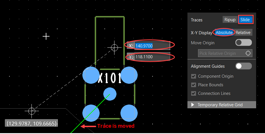 You can move design objects in the following ways:
- Moving the cursor.
The object moves to the location of the cursor. - Entering coordinates in the X and Y fields manually. Pressing the Tab key shifts the keyboard focus to the X and Y fields in the design canvas. The object moves to the location specified in the X and Y fields.
- Using shortcut keys. Press A, D, W, or Z to move an object in the left, right, up, or down directions, respectively. The object moves by one grid point relative to the last location of the object.
- Moving the cursor.
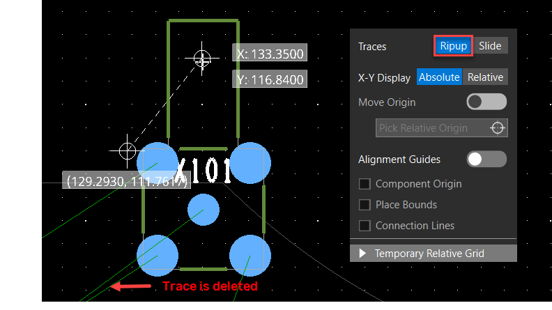
- Select Ripup or press Shift+E for Traces to delete them when the object moves. When multiple objects are selected, the layout editor does not rip up traces that are fully contained within the selection set.
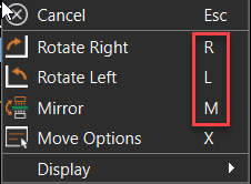
- Right-click and choose the Rotate Left, Rotate Right, and Mirror options from the pop-up menu to rotate or mirror the object at the current cursor location. You can also use the shortcut keys R, L, and M to rotate and mirror.
- Select X-Y Display to Relative to move objects in the relative mode as described in the following steps:
- Move the object incrementally in line from the original position cursor or press the Tab key to manually enter the incremental value for the DX and DY locations.
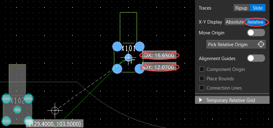
- Optionally, toggle Move Origin, select Pick Relative Origin, and click in the design canvas to shift the origin to a new location.
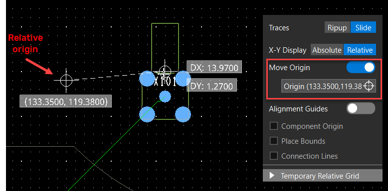
- Move the object incrementally in line from the original position cursor or press the Tab key to manually enter the incremental value for the DX and DY locations.
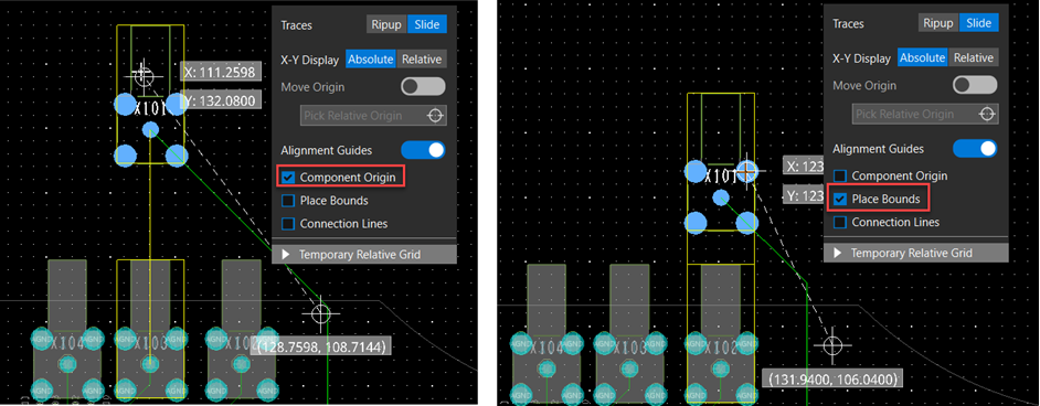
- Optionally, select the Alignment Guides options to pick the new location aligned with Component Origin, Place Bounds, Connection Lines, or in combination of these options. Align guidelines become visible and dynamically change as you move the object. The following image illustrates dynamic align guides when the origin and place bounds shape of the components are used for alignment:
- Click to choose the location to which to move the object. If you are manually entering the X and Y coordinates, press the Enter key.
The object appears at its new location. Depending on how the Traces field is set, the traces connected to the objects are either stretched or deleted.
Moving Objects Using Relative Grid for Efficient Placement and Routing
The Temporary Relative Gridoption of the move command is useful when aligning components to other objects such as components, pins, or vias. When selected, you can set a temporary grid origin and adjust X and Y grid spacing for efficient placement and routing. To move objects with a relative grid, do the following:
- Invoke the move command and expand the Temporary Relative Grid accordion.
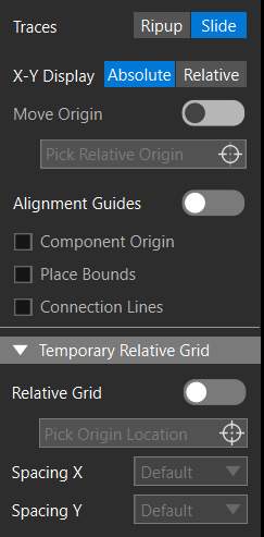
- Double-click the Spacing X field and enter the relative grid value for the X direction. Similarly, modify the Spacing Y value. By default, the existing grid values are used.
- Select Relative Grid, Pick Origin Location, and click in the design canvas to pick an origin for the temporary relative grid. The new grid points become visible.
- Select a component in the design canvas. The component attaches to the cursor.
- Move the cursor to pick a new location and click to confirm the placement. The component snaps to the relative grid point.
Measuring the Distance between Objects in OrCAD X Presto
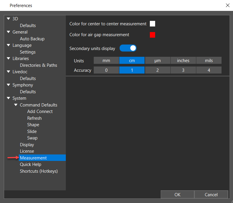
Measuring the distance between objects displays the air gap between selection points. If pins or vias are selected, the center-to-center spacing is also measured. The measurement results can be customized to display the data with dual units and accuracy in a user-defined color. You can measure the distance in 2D as well as 3D mode. You can capture the measurements using your system's screen capture command or PrtScn shortcut key.
To measure the distance between two objects in 2D, do the following:
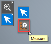
- Right-click the Select icon from the command toolbar and select the Measure icon. Alternatively, press and hold the Alt key.
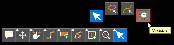 Shadow mode is temporarily enabled, and the measurement mode is active.
 - Click to choose the first object in the design canvas. The selected object is highlighted in the canvas.
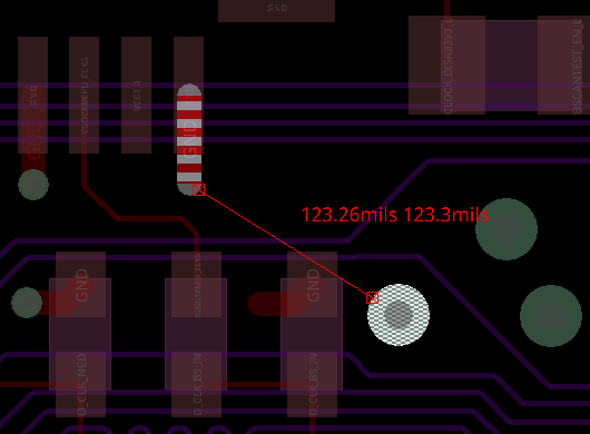
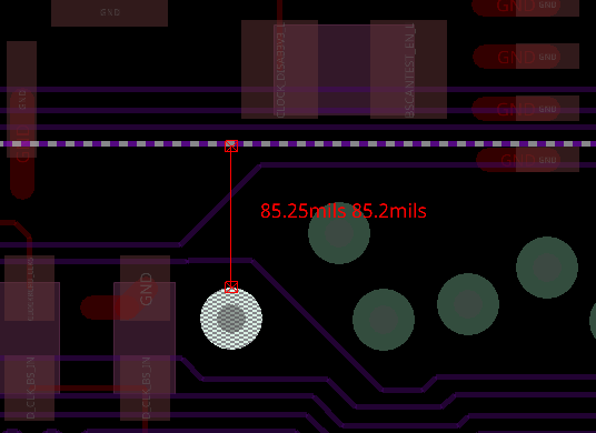
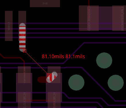
- Hover the mouse over the second object you want to measure. The second object is temporarily highlighted. A rectangle with two cross lines connecting two opposite corners indicates the point on an object where the air gap is measured. The air gap distance between the selected objects is represented by a dynamic straight red line drawn between the centers of the two markers. The air gap measurement displayed in red includes both primary and secondary units.
 If the selected object is a pin or via, the center-to-center spacing between them is also displayed, in white color, indicated with (c).
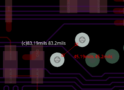
- Hover over another object to choose a different object, The first object remains the same, and the second object changes. The dynamic line also changes and displays the air gap between objects.
- Repeat the previous step to choose different objects to dynamically see measured distance values between the first and new objects.
- Click another object to reset the selection of the first object, The selected object is highlighted and defined as the first object.
- Choose Edit – Preferences to modify the measurement settings. The Preferences dialog box opens.
- Press Escape or release the Alt key to exit measure mode, Shadow mode is also exited. To measure the distance between two objects in 3D, do the following:
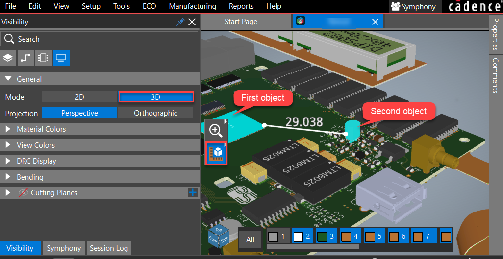
- Switch to 3D mode in the Display tab of the Visibility panel. The 3D view of the design opens.
- Right-click the Select icon from the command toolbar and select the Measure icon. Alternatively, press and hold the Alt key. The measurement mode is enabled.
- Click to choose the first object. The selected object is highlighted.
- Hover the mouse over the second object you want to measure. The second object is temporarily highlighted. The distance between selected objects is displayed in white.
- Press Escape to exit the measure mode.
Swapping Components, Diff Pairs, and Pins in OrCAD X Presto
Components, pins, and diff pairs can be swapped to reduce trace lengths and uncross flight lines to improve routing and placement, particularly in complicated PCB designs with high pin count components, such as DDRs, FPGAs, and microcontrollers.
To enable the swap commands in OrCAD X Presto, do the following:
- Right-click the Move icon in the floating command toolbar and select the Swap icon.
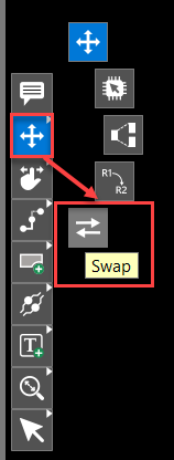 A floating command window opens with three tabs: Pins, Diff Pair, and Components.
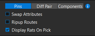
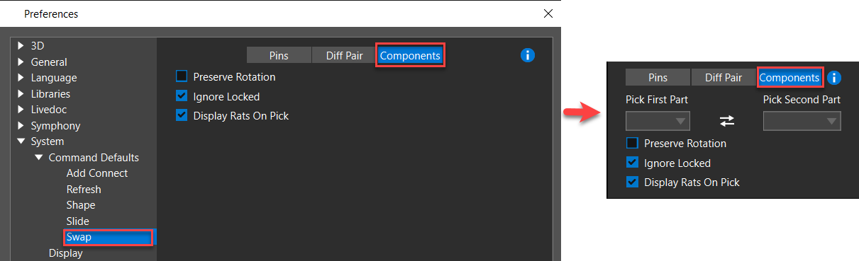
- Modify the default settings of the swap floating command window using the Preferences dialog box.
- Optionally, assign a shortcut key or hotkey to access the swap commands quickly. You can assign shortcuts in the Preferences dialog box.
Swapping Pins in OrCAD X Presto
You can swap two pins if they have the same PIN USE values. The property LAST_PIN_SWAP is attached to pins and tracks all swapped pins. The value of the property is the name of the pin with which it was last swapped. To swap pins in OrCAD X Presto, do the following,
- Right-click the Move icon from the floating command toolbar and select the Swap icon.

- Choose Pins in the floating command window and hover the cursor over the
 icon to display the guiding image.
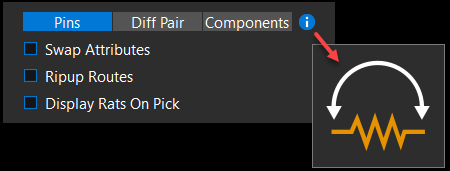
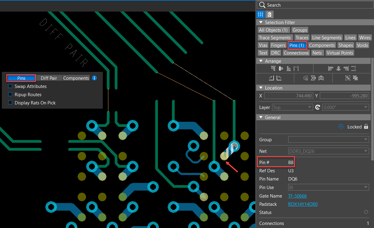
- Enable Pins in the Selection Filter.
- Click to choose the first pin to swap. The chosen pin, flight lines, and all pins available to swap become highlighted.
- Choose the second pin to swap from the highlighted pins. The swapping is completed as displayed in the Session Log window.
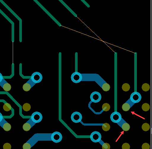 If you choose a pin that is not highlighted, the Session Log window prompt explains why the pin is not swappable.
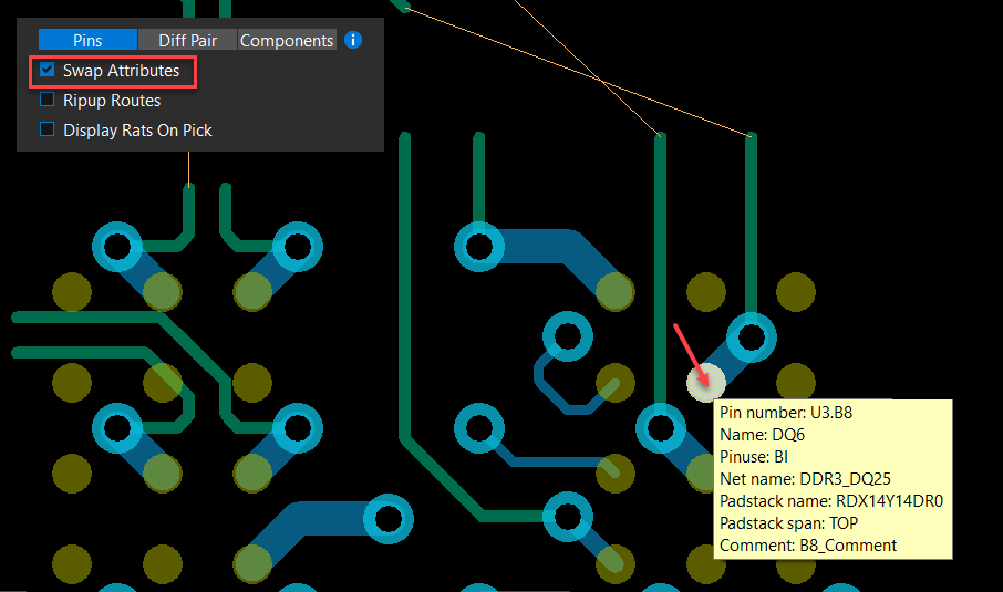
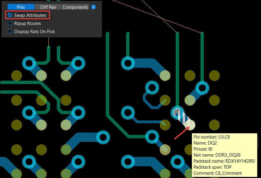
 - Enable the Swap Attributes check box and select the pins to swap. Pins are swapped with their attributes, which you can specify in the Attributes section of the Properties panel. The following image illustrates the pin swap with their attributes:
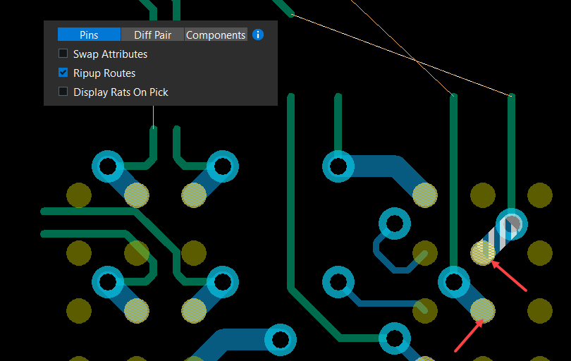
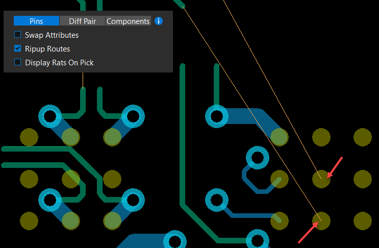
- Enable the Ripup Routes check box and select the pins to swap. Pins are swapped with their etch elements removed. The following image displays the removal of associated etch and vias after pin swapping:
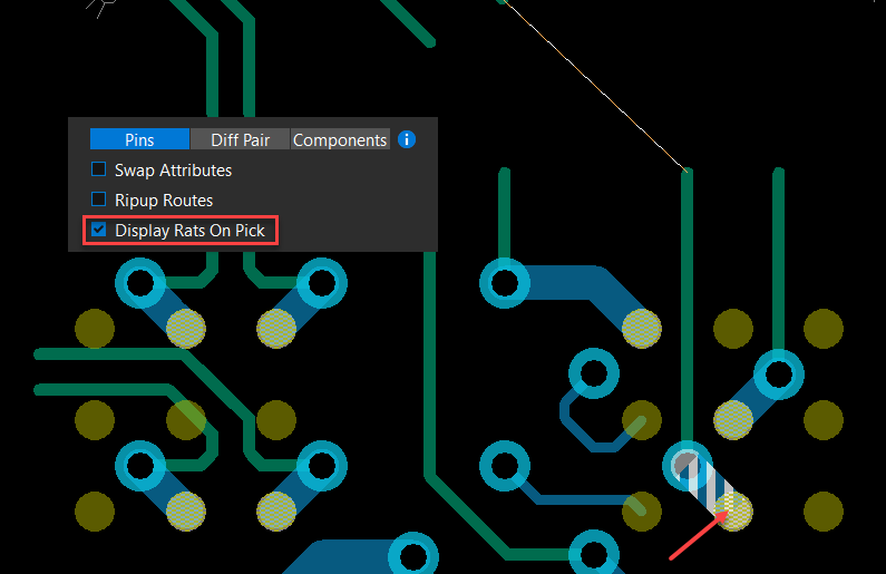
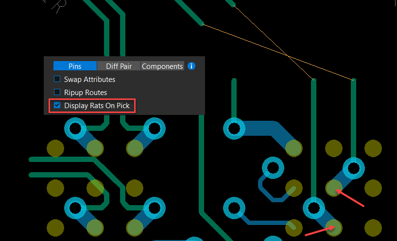
- Enable Display Rats on Pickcheck box and select the pins to swap. Rats are displayed when the pins are for swapping, as follows:
- Select pins to remain in the pin-swapping command or press Escape to exit the command.
Swapping Diff Pairs in OrCAD X Presto
Diff pair swapping has two modes: Diff Pair Swap and Polarity Swap. The Diff Pair Swap mode swaps two pins at one end of a diff pair with two pins at one end of another diff pair. The Swap Polarity mode swaps the negative and positive pins at one end of a single diff pair. The property LAST_PIN_SWAP is attached to pins and tracks all swapped pins. The value of the property is the name of the pin with which it was last swapped.
To swap diff pairs in OrCAD X Presto, do the following:
- Right-click the Move icon from the floating command toolbar and select the Swap icon.
 The Swap icon becomes active in the toolbar, and a floating command window opens with three tabs: Pins, Diff Pair, and Components.
 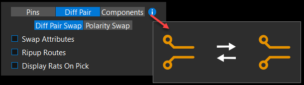 Choose Diff Pair Swap in the swap command window and hover the cursor over the icon to display the guiding image.
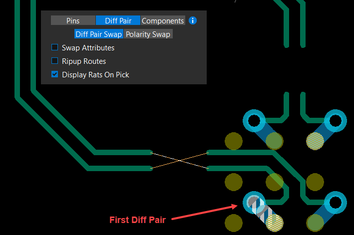
- Enable the Display Rats On Pick check box. Use this option if rats nests display is turned off in the design.
- Select Pins in the Selection Filter.
- Choose a pin of a diff pair net to indicate the first pin pair to swap. The chosen pin, flight line, and eligible pin of other diff pair nets become highlighted.
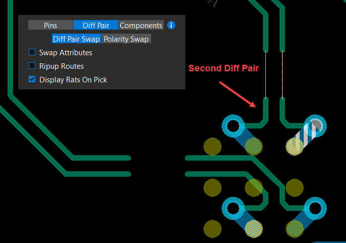
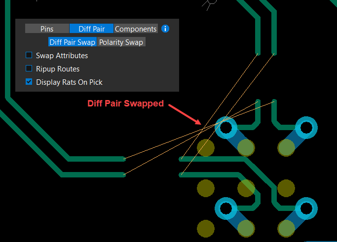
- Choose a pin of another diff pair net from the highlighted pins to swap. The pins of the diff pair nets are swapped, as follows:
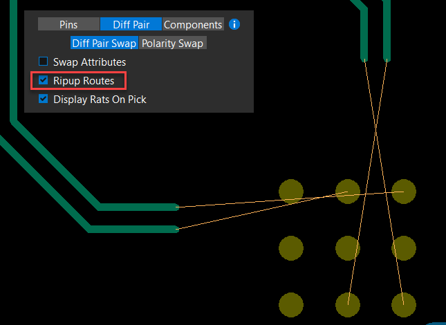
- Enable the Ripup Routes checkbox and select diff pair pins to swap. The pins of the diff pair nets are swapped with their etch elements removed, as follows:
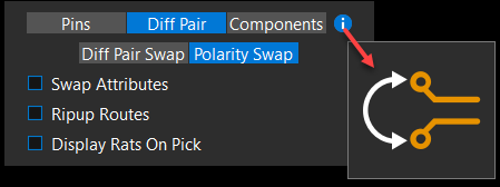
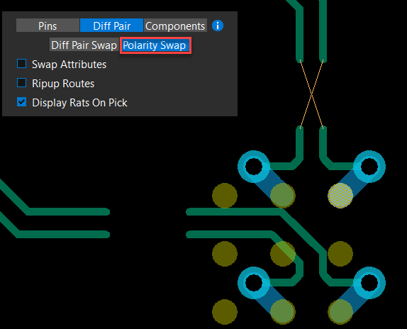
- Choose Polarity Swap in the floating command window and hover the cursor over the icon to display the guiding image.
- Enable the Display Rats On Pick check box if the rats nests are not visible in the design.
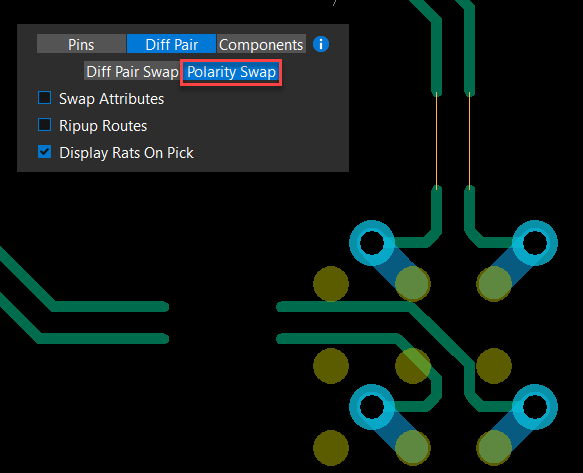
- Choose a pin of a diff pair to swap pin polarity. The polarity of the pin pair is swapped, as follows:
- Select pins to remain in the pin-swapping command or press Escape to exit the command.
Swapping Components in OrCAD X Presto
You can swap components in OrCAD X Presto by choosing them in the design canvas or the combo box of the swap command floating command window. The locked components cannot be selected for swapping and should be unlocked manually.
To swap components:
- Right-click the Move icon from the floating command toolbar and select the Swap icon.

- Choose Components in the floating command window and hover the cursor over the icon to display the guiding image.
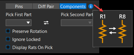
- Select the first component in the design canvas or in the Pick First Part pull-down list. This list displays reference designators of unlocked components.
The component is highlighted, and its reference designator is displayed in the Pick First Part combo box.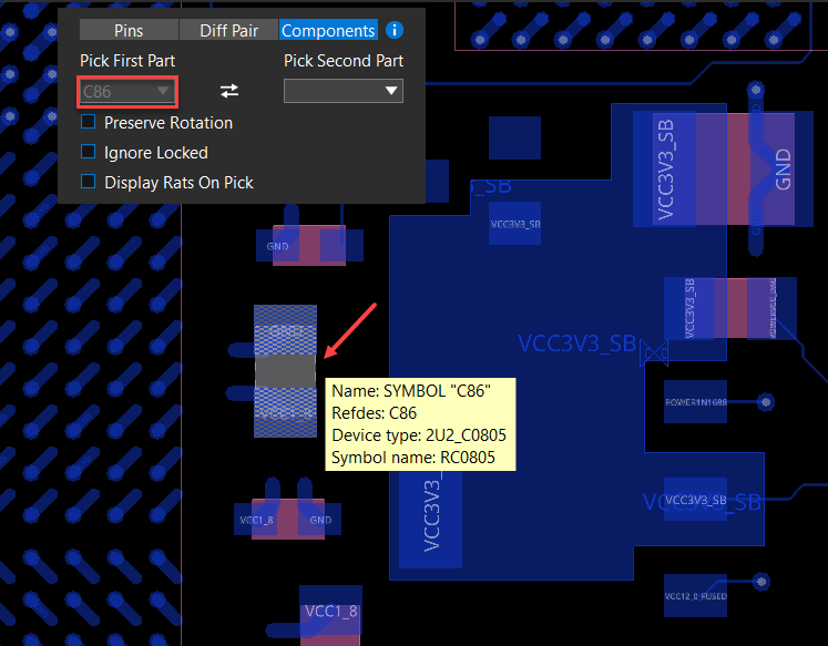
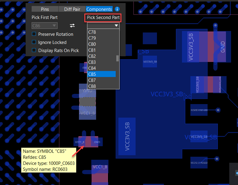
- Click the second component in the design canvas or select the reference designator in the Pick Second Part pull-down list .
 The components are swapped, and DRCs are displayed for any violation resulting from the component swapping.
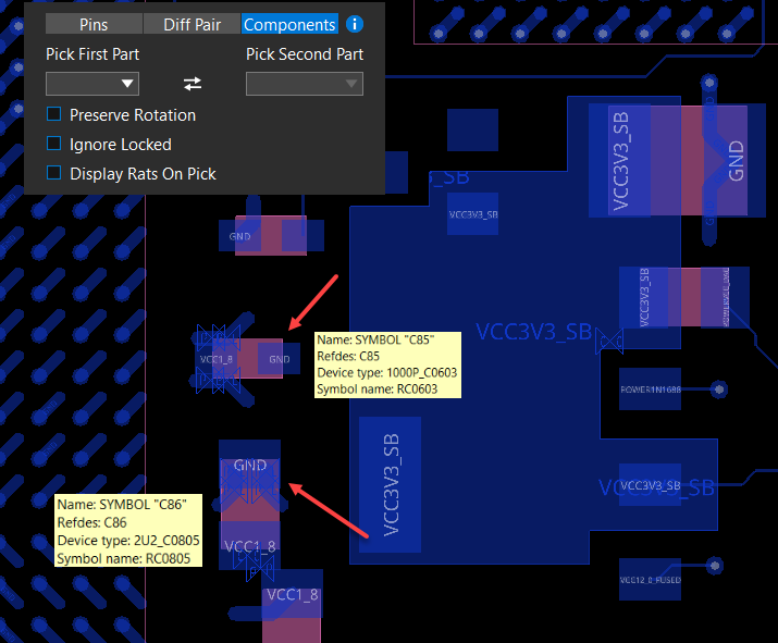
- Enable the Ignore Locked check box to select locked components for swapping.
You can lock and unlock a component by clicking the ![]() in the Property panel.
in the Property panel.
- Enable Preserve Rotation check box to retain the orientation of the swapped components.
- Select components to continue swapping or press Escape to exit the command.
Creating Custom Design Outline in OrCAD X Presto
The custom design outline can be interactively created in rectangular, square, circular, or polygon shapes in OrCAD X Presto. When creating a design outline by drawing shapes, arcs, and lines, the specific measurements are dynamically shown to assist the drawing creation. The new design outline replaces the existing design outline in the canvas. Additionally, conductor and component keep-in shapes are re-generated based on the settings in the Property panel.
To modify the default design outline, do the following:
- Choose ECO – Draw Design Outline from the main menu. A floating command window opens, displaying design outline drawing parameters. The default is a Polygon.
- Click to select the existing design outline. The design outline shape is highlighted, and the Property panel displays the drawing details.
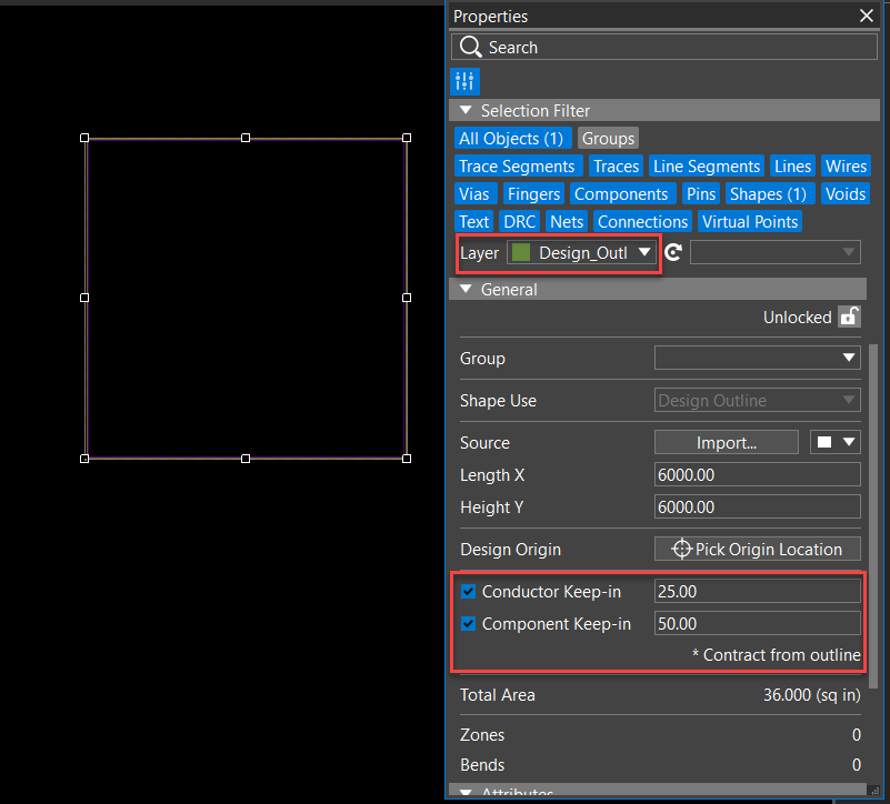
- Review the Property panel settings for Conductor Keep-in and Component Keep-in. Modify the settings as required.
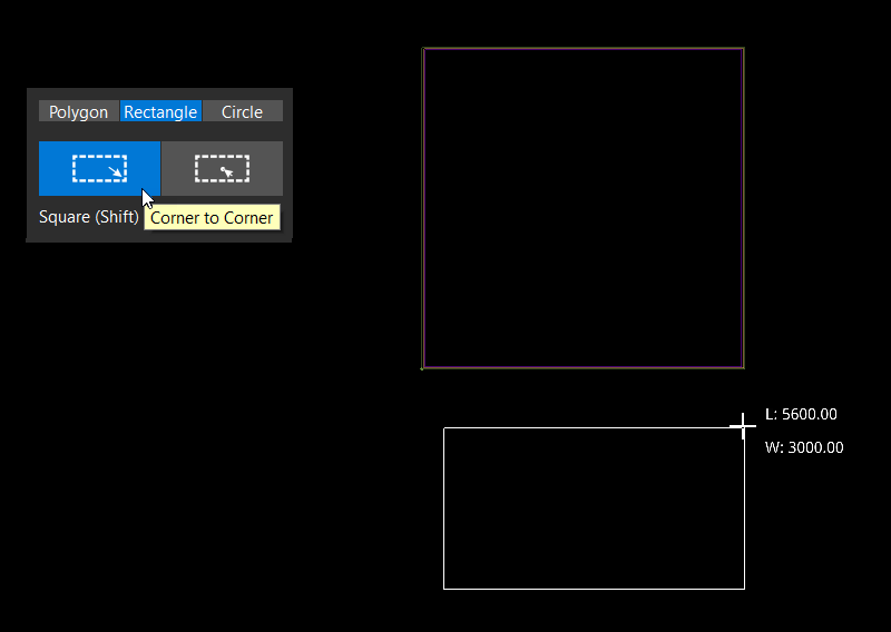
- Draw a new rectangular or square design outline as follows:
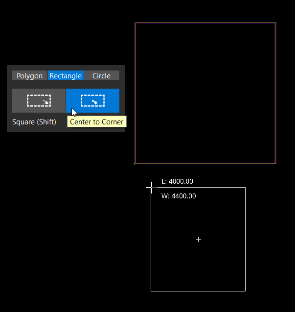
- Select the Corner to Corner or Center to Corner mode in the floating command window. Press Shift while selecting the mode to create a square outline shape.
- Locate the coordinates by moving the cursor where you want to start the outline and click on the design canvas. Creating Custom Design Outline in OrCAD X Presto
- Move the cursor in the desired direction, following the dimension values displayed with the cursor movement. The second corner is attached to the cursor location and dynamically displays the dimensions as you move the cursor.
Press the Backspace key to undo the last action.
- Press Enter or click on the design canvas to complete the rectangle design outline shape.
The new rectangular design outline replaces the existing design outline. The keep-in shapes are regenerated as per the settings in the Property panel.
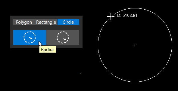
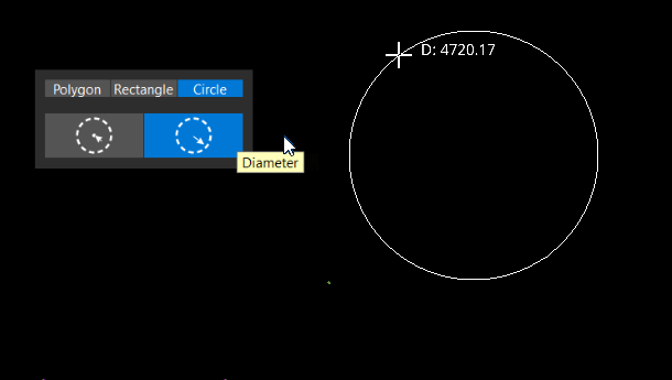
- Draw a circular outline using the following steps:
- Select the Radius or Diameter mode in the floating command window.
- Locate the coordinates by moving the cursor where you want to start the outline and click on the design canvas. The selected point is used as the center or a point on the circumference of the circle, depending on the mode enabled in the command window.
- Move the cursor to draw a circle with the required radius or diameter. The circle dimensions are dynamically displayed as you move the cursor.
- Press Enter or click on the design canvas to complete the circular design outline shape.
The new circular design outline shape replaces the existing design outline. The keep-in shapes are regenerated as per the settings in the Property panel.
- Draw a polygon shape design outline by performing the following steps:
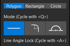
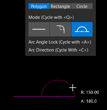
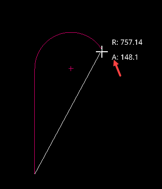
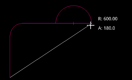
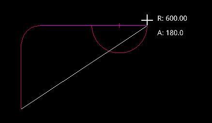
- Select Line, Tangent Arc, or Perpendicular Arc modes in the floating command window. The center point of a Tangent Arc is orthogonal to the line segment it is connected, and mouse movements draw a 45-degree arc. The center point of the Perpendicular Arc aligns with the line segment it is connected to, and mouse movements draw a 180-degree half-circle. The arc can be drawn on either side of the line segment.
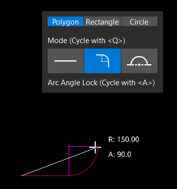
- Locate the coordinates by moving the cursor where you want to start the outline and click on the design canvas. The selected point is used as the starting point.
- Move the cursor to draw a line, arc, or half circle. The dimensions are dynamically displayed as you move the cursor.
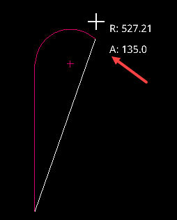
- Optionally, press the A key to toggle the angle lock values for a line or arc from 90 and 45 degree to any angle.
- Optionally, press the C key to change the arc direction for half circle.
- Keep drawing to complete the polygon shape design outline.
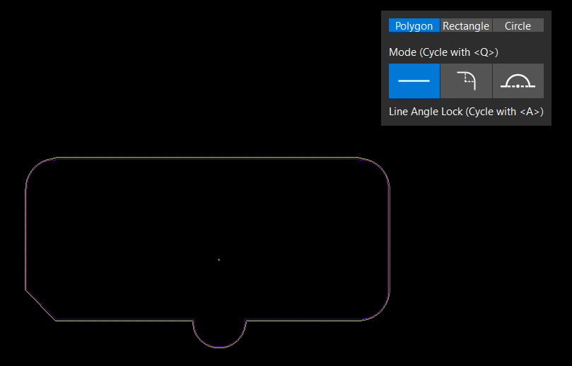 The new polygon shape design outline replaces the existing design outline. The keep-in shapes are regenerated as per the settings in the Property panel.
- Select Line, Tangent Arc, or Perpendicular Arc modes in the floating command window. The center point of a Tangent Arc is orthogonal to the line segment it is connected, and mouse movements draw a 45-degree arc. The center point of the Perpendicular Arc aligns with the line segment it is connected to, and mouse movements draw a 180-degree half-circle. The arc can be drawn on either side of the line segment.
- Press the Escape key to exit command.
Cutting Traces
OrCAD X Presto provides an easy way to cut one or more traces into two on single or multiple layers. This feature is helpful to move or edit routed designs or create designs for reuse. To cut through traces in a design, follow these steps:
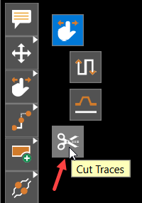
- Expand the Slide icon in the command toolbar and choose Cut Traces.
A single field to specify the cut width is displayed with a default value in the current design unit and accuracy.
- Modify the value of Cut Width.
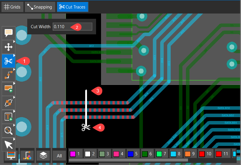
- Click on the design canvas to pick a starting point for cutting traces. The cursor changes to scissors.
- Move the cursor in any direction. As you move the cursor, a rubber band straight cutting line is drawn from the first pick point to the current location of the cursor point, and all visible traces on different layers that intersect with the rubber band straight cutting line are temporarily highlighted.
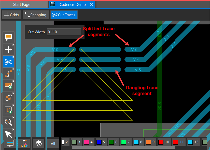
- Click again to pick the end point of the cut line. The cutting line is erased. All intersected visible traces on different layers are dehighlighted and cut into two parts with the specified cut width where the line was drawn. Trace segments, after splitting, retain their net names if connected to object pins on both sides. Otherwise, they become dangling traces with no net assigned. If a trace is locked, it cannot be cut.
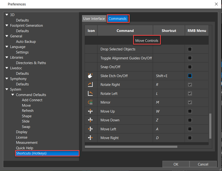
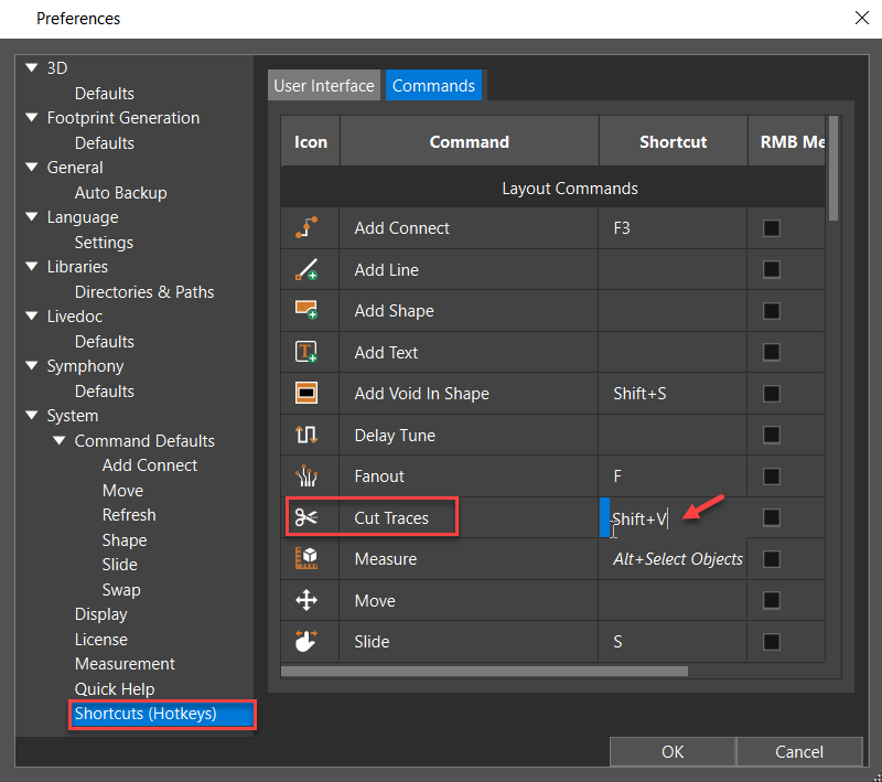
- Choose Edit – Preferences to assign a shortcut key for the cut trace command. Open the Commands tab of the Shortcuts (Hotkeys) category and press the key you want to assign. For example, the following image shows Shift+V is assigned as a shortcut to perform the cut traces command.
View the next document: 07 - Managing Shapes in OrCAD X Presto
If you have any questions or comments about the OrCAD X platform, click on the link below.
Contact Us