04 - Getting Familiar with User Interface of OrCAD X Presto
OrCAD X Presto has an easy-to-use interface that makes navigation intuitive, quick, and accessible. Knowledge of its interface elements helps you work more efficiently and save time.
Open Directory of the Current Design File
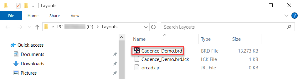
When working on multiple layout designs, navigating to the current design file directory buried deep in various subfolders on your system is time-consuming. In OrCAD X Presto, you can quickly open the current design file directory with a single click.
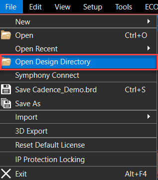
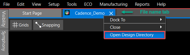
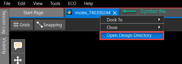
The Open Design Directory opens the active design file (.brd, .dra) directory in File Explorer. This option is accessible from the File menu or as a shortcut menu on the file name tab.
Locking Database Files in OrCAD X Presto
To protect your design, you can lock specific aspects of the database so they cannot be changed by others. This lets you control your design data by choosing which export options to lock. Once locked, that particular save and export functionality becomes unavailable if you share your design with others.
- Choose File – IP Protection Locking to ensure any unsaved design work has been saved. The IP Protection Locking dialog box opens.
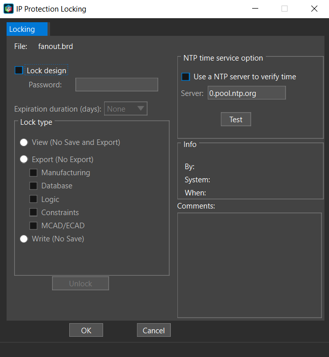
- Select the Lock design check box . The fields and check box option become active.
- Enter a password. It may contain a maximum of 20 alphanumeric characters. Invalid charac- ters are: spaces, backslashes (\), and dashes (-). Passwords are case-sensitive.
It is extremely important that you keep a record of any passwords used to lock databases. The recovery of databases in a locked state due to forgotten passwords is not supported.
- Perform any of these optional actions:
- Choose Expiration duration (days) from the drop-down list.
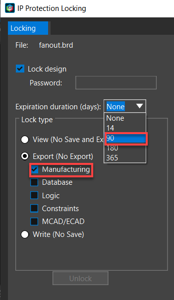
- Check one of the lock modes. This option prohibits the export of design data on View lock and Export lock databases. For Write lock databases only prohibits database saves but allows the export of design data.
- Choose Expiration duration (days) from the drop-down list.
- Choose options for locking the database and click OK. A dialog box opens and prompts you to confirm the password. The locked database is saved and becomes an active database. The database file name gets automatically updated and assigned a prefix based on the selected lock mode as follows:
- View Lock: <design_name>_view_locked
- Export Lock: <design_name>_export_locked
- Write Lock: <design_name>_write_locked
- Check Use an NTP server to verify time. The Server field becomes active.
- Specify the server name.
- Enter additional comments.
When locked, other users can view your design but receive the following error message when attempt- ing to alter and save or export protected functionality, depending on your lock mode settings. 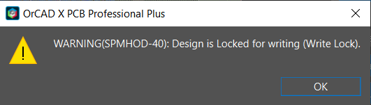
Context-Sensitive Pop-Up Menus in OrCAD X Presto
A context-sensitive pop-up menu lists actions relevant to a specific user interaction. It is available with a right mouse button (RMB) click and appears as a floating window. Context-sensitive pop-up menus help perform interactive commands, such as Add Connect, Slide, Add Shape, and so on, by minimiz- ing mouse clicks. The menu items change dynamically based on the objects selected in the canvas and the interactive command you are in. Each menu item has an icon displayed on the left of the menu label, and a shortcut key for the menu is appended to the right. If a menu does not have an associated icon or does not define a shortcut, they are not displayed.
Default Pop-Up Menus for Display Controls
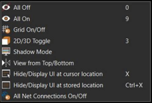 When nothing is selected in the design canvas, regardless of whether any interactive command is active or not, the right mouse button pop-up menus provide a convenient way to perform display control actions. These menu items are available by default.
Context-Sensitive Pop-up Menus for Interactive Commands
When an interactive command is active and applicable to selected objects, the context-sensitive pop- up menus are divided into three sub-menus displaying the following:
- Command control options, such as Backup (Oops) and Cancel
- Command-specific control options that are applicable at the current command state
- Display control options
For example, the pop-up menu for the Add Connect command is as follows: 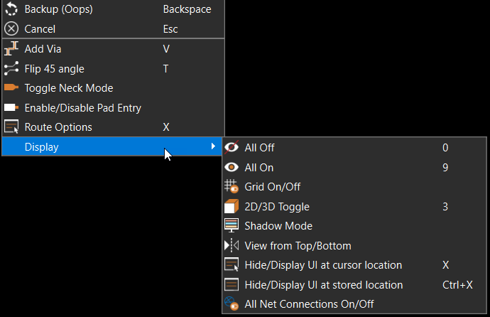
However, if the selected objects are not relevant to the active command, the pop-up menu displays the following:
- General edit options, such as Copy, Delete, Move
- Arrange options, such as Rotate X, Flip Y
- Display control options
For example, in the Slide command mode, when a symbol is selected, the following pop-up menu is displayed: 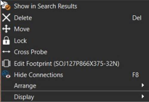
The pop-up menus can be customized to optimize and personalize your design experience. The con- trols for specific commands are defined in the Commands tab of the Shortcuts (Hotkeys) section of the Preferences dialog box.
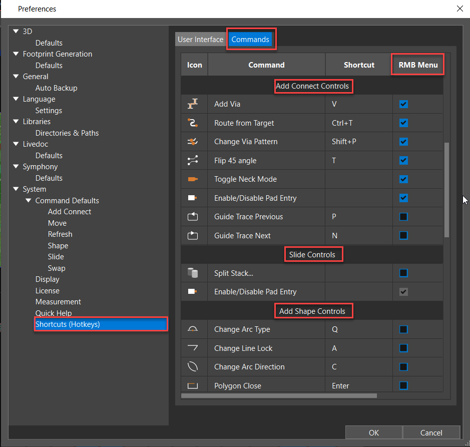
You can configure the command control options by selecting or deselecting the checkboxes under the RMB Menu column for a specific command. You can also change the shortcut key assignment for a command control. The default menu items are grayed out and cannot be deselected. For example, the Enable/Disable Pad Entry control is selected by default for the Slide command and cannot be removed from the pop-up menu.
Show and Hide Command Windows
Command windows are, by design, floating and positioned at the top-right corner of the design canvas. Moving them outside the design canvas maximizes the real estate available for designing. You can do it by docking a command window as a panel or hiding it from the canvas. You can display a docked or hidden command window to design the canvas using shortcut keys or pop-up menu commands.
Docked Command Windows
The command windows, by default, can be docked as panels as set in the Preferences dialog box.
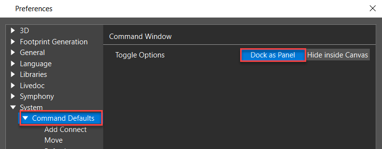
You can dock command windows to the left, right, or bottom of the main window, similar to the existing panels, such as Properties, Visibility, and Session. When docked, they appear as a separate tab with the name Options on the bottom of the panel. The layout editor saves the location of a docked panel and uses it for all command windows until you change it.
In the docked state, the command button in the top quick access toolbar is dehighlighted. While in the floating state, it is highlighted. You can toggle between the docked and floating state by clicking the command button in the top quick access toolbar. 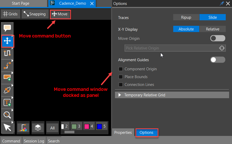
To undock a panel, select and drag it with the mouse to float it in the design canvas or outside the ap- plication window. The status and location of the undocked floating panel are used for all the command windows and are also remembered by the layout editor across designs and sessions.
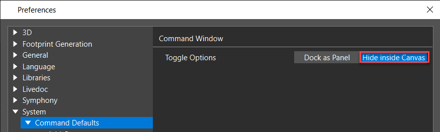
Hidden Command Windows
Command windows can be hidden from the design canvas by setting the Command Window preference to Hide inside Canavs. When hidden, the command button in the top quick access toolbar is dehighlighted. You can toggle between the hidden and floating state by clicking the command button in the top quick access toolbar.
Display Floating Command Windows
You can view the floating command window in the design canvas using the following methods:
|
Display Floating Command Window in Design Canvas |
Using |
|
At the cursor location |
|
|
At the stored location |
|
Snapping Controls in OrCAD X Presto
The grid provides a basic structure for placing objects by snapping them to predefined intervals. How- ever, during command execution, objects may need to be moved to an off-grid location.
Object Snapping
Object Snap allows the cursor to snap to an object that differs from the value set in the grid.
Object snapping ensures the precise selection of specific locations on existing design objects, such as the origin of a pin or via, the center of a component or circle, the vertex of a shape or bond wire, and the midpoints of segments. The priority of object snapping is determined from top to bottom and
from horizontal to vertical order, which means Segments Vertex has the highest priority and Shapes Midpoint has the lowest priority. 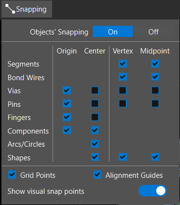
Grid Points
When selected, Grid Points snap the cursor to the nearest grid location. The grid points are used for snapping if no snapping object is found nearby or the object's snapping is off.
Alignment Guides
When selected, Alignment Guides display dynamic guidelines connecting the cursor with the nearest alignment points on existing components within the snapping range. This visual aid helps in component placement and alignment.
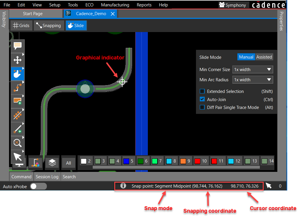
Visual Snap Points
When the Show visual snap points option is selected, the current snap point location is displayed as a text indicator on the Status Bar at the bottom right of the application window. A graphical indicator, a circle with two cross lines, is displayed in the design canvas at the current mouse location before you pick the snapping point.
Visualize Objects Using Shadow Display
Shadow mode helps you view components and navigate nets in complex designs. It enables you to focus on selected objects while dimming the visibility of other objects. You can modify the visibility of both selected and unselected objects in a design using shadow mode. You can adjust the shadow mode setting from the Display tab in the Visibility panel.
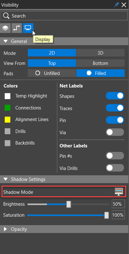
When shadow mode is activated, selected objects are displayed in their layer color, while unselected objects are dimmed based on the specified brightness and saturation values in percentage. The de- gree of dimming for unselected objects can be adjusted using the Brightness slider. Setting the bright- ness to a minimum (25%) displays unselected objects in their layer color without any dimming.
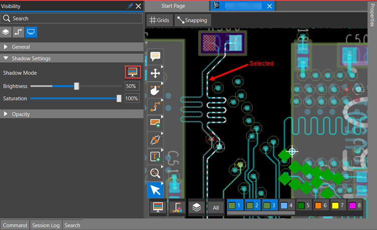
Clicking the Shadow Mode icon cycles through one of the following three states:
|
Shadow Mode Setting |
Icon |
Display Status |
|
Shadow Off (default) |
|
Default display.
|
|
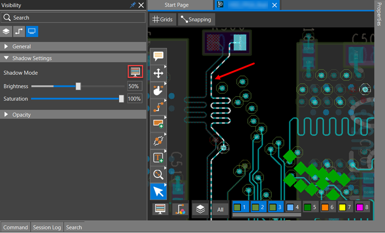
Shadow On |
|
Partial shadow mode is on. Selected objects are displayed in their layer or assigned custom colors. Non-selected objects are dimmed.
|
|
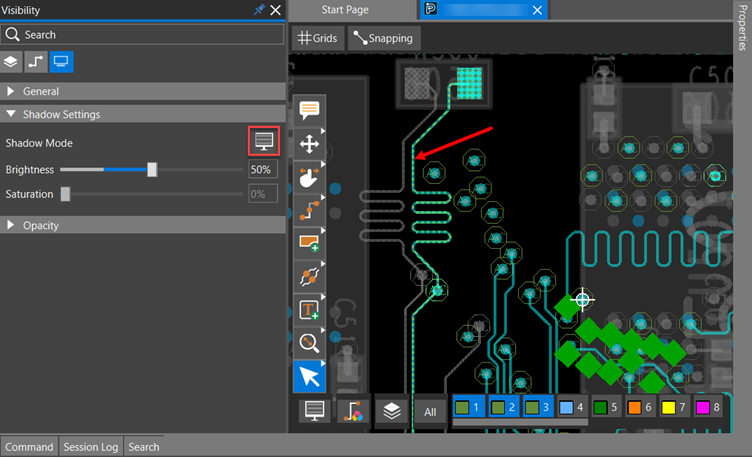
Ultra Shadow |
|
Complete shadow mode is on. Select- ed objects are displayed in their lay- er or assigned custom colors. Non-se- lected objects turn grey, as they are in saturation zero.
|
The shadow mode control icon is also available in the floating layer toolbar. 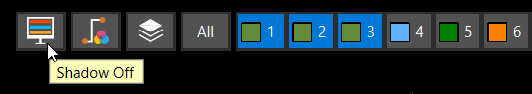
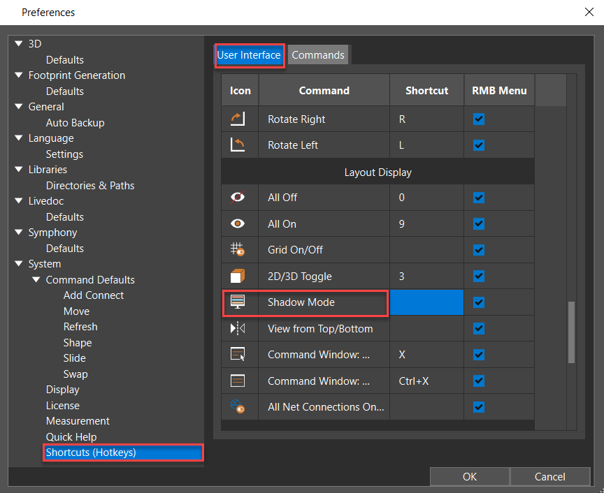
You can also assign a shortcut key to cycle through shadow mode states. Open the Preferences dialog box, select the shortcut cell, and press the ASCII keys not being used for any other operation.
Use the shadow mode icon in the Reports panel to quickly analyze selected objects.
View the next document: 05 - Setting Up the OrCAD X Presto Design Environment
If you have any questions or comments about the OrCAD X platform, click on the link below.
Contact Us