03 - Authoring and Editing Footprints in OrCAD X Presto
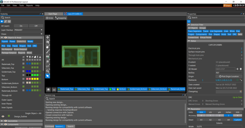
Launch OrCAD X Presto, and open an existing PCB symbol .dra file. 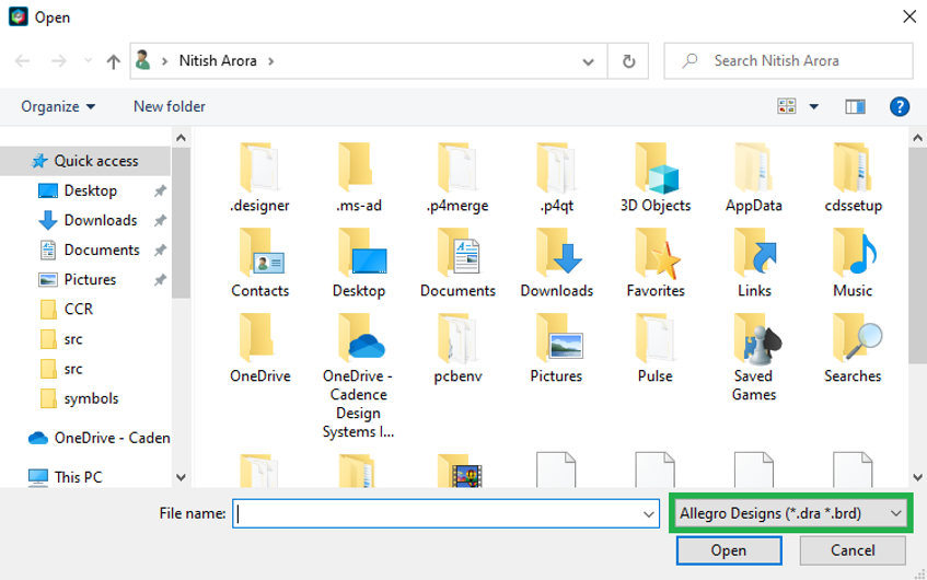
You can switch between opening .brd and .dra files in same session.
Editing Footprints
Open your layout design in OrCAD X, and do the following:
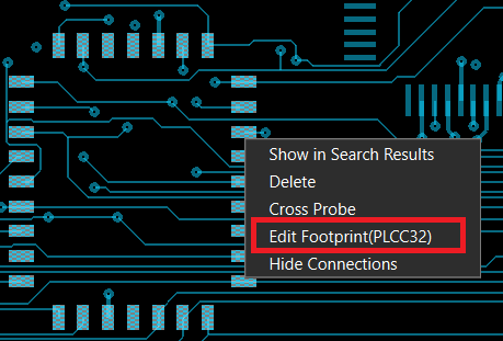
- Right-click on a symbol and choose Edit Footprint.
 If you have defined the footprint, you see the following dialog box, while the Footprint Editor is opening.
 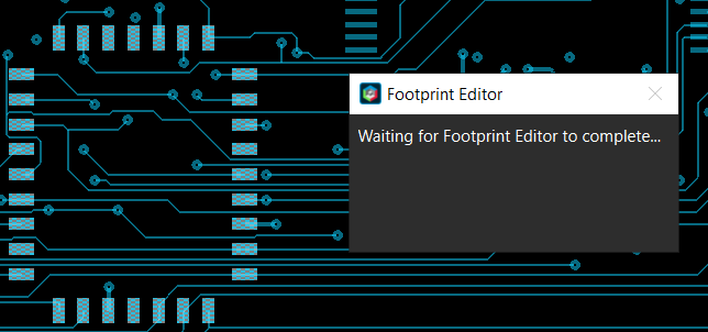 The symbol opens in another instance of OrCAD X—that is, the Footprint Editor (which uses the same license as the parent application, so you do not need an additional license).
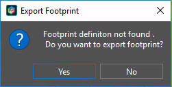
If you have not defined the footprint, you see the following dialog box:
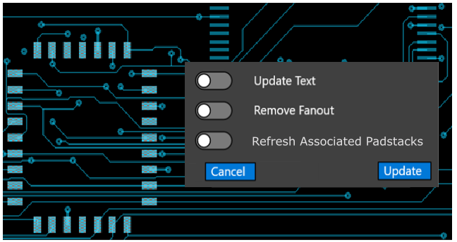
- Modify the footprint as necessary, and click Save to exit the Footprint Editor. The main design canvas is locked while you are editing the footprint.
- Set the on/off sliders as necessary in the following form and Update to save. Your edited symbol is updated in the design.
Adding Pins to a Footprint in OrCAD X Presto
In OrCAD X Presto, you can add a pin to a PCB symbol using one of the following three methods:
- Add a pin by searching for padstacks.
- Build or add a pad using the Padstack Wizard (available in OrCAD X Professional only).
- Build or add a pad using the Padstack Editor.
Adding Pins by Searching Padstacks
When you choose Place pin by search, a search panel opens at the bottom of the UI that shows a list of all pads in the $padpath and current working directory.
Single-click on a pad from the list in the search panel to show the pad information in the Properties panel.
Double-click on a pad from the list to choose the padstack, which is attached to the cursor. The Add pin widget opens, as follows, and the command add pin is active for you to place your pin on the canvas. 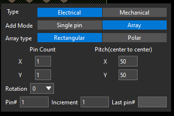
In the search widget, there is a library table and Browse button.
- Library shows the list of pads in their library and the current working directory.
- Browse opens a file browser and enables you to navigate and choose a .PAD from any location. When you browse to choose a PAD, the .PAD file is copied into your working directory and the selected pad is attached to your cursor for placement.
- The Settings button opens the user preferences dialog for you to modify the padpath.
When choosing a thru hole padstack, the property panel shows the attributes of the thru hole pad and a TOP view of the padstack.
When you choose a Surface mount pin, the property panel appears similar to the following: 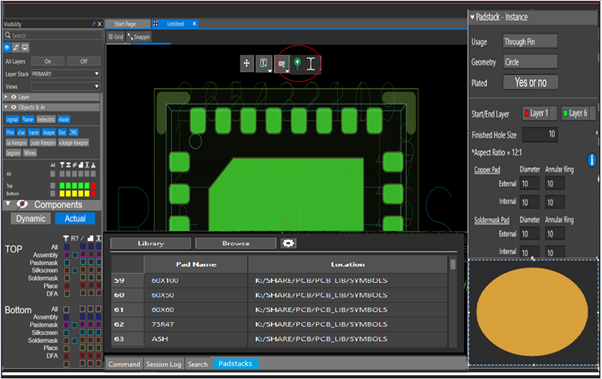
Adding Pins with the Padstack Editor
To launch the padstack editor, choose the third option from the floating Add Pin toolbar. You can create a new padstack or open an existing padstack and make the modifications. 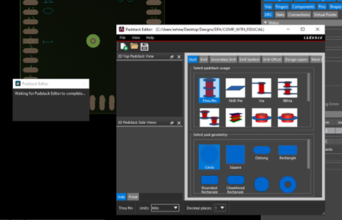
The menu option Add Padstack and Exit is available only when launched from the Footprint editor. This option prompts you for the padstack path and then exits.
On exit, the padstack editor closes and the Add pin command is available. Use the add pin widget shown below to modify pin details and place the pad on the canvas. 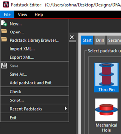
Right-click on an existing padstack for the Modify padstack to open the padstack editor.
Adding Pins with the Padstack Wizard
The wizard utility can guide you through required inputs to add or create a new padstack, as follows:
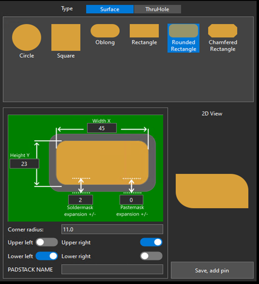
You can enter padstack parameters like width, height, diameter and other relevant details, based on your choice of six available pad shapes, as seen above.
Soldermask and pastemask expansion creates a padstack on the soldermask top and pastemask top. The shape of the padstack created remains the same as the shape selected in the UI, and the dimensions depend on the soldermask/pastemask expansion specified in the UI. For example, if the width of the design padstack specified is 45, then the width of the padstack created on soldermask top will be 45 +/- soldermask expansion. A similar calculation is applicable for pastemask.
The Wizard shows a 2D view of the padstack, which is dynamically created based on the shapes and dimensions you provide.
When you click the Save button, the padstack is validated for any errors. Any errors are displayed in the session log. Once all errors are cleared, the padstack—with name test.pad—is created on the
disk (in the first path picked from the $padpath user setting). If no path exists, it skips to the next path mentioned in the $padpath. If there are no errors, the add pin command is active for entering pin details.
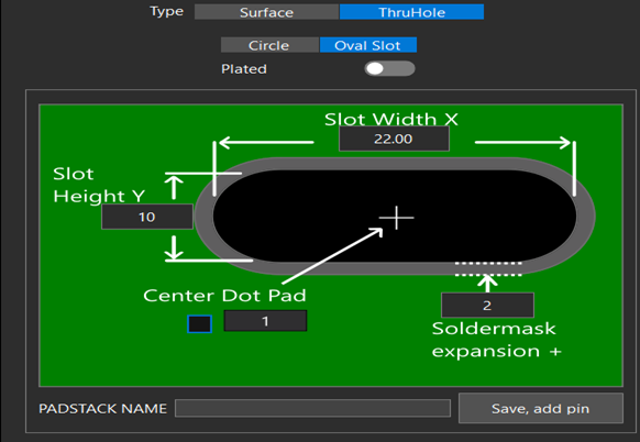
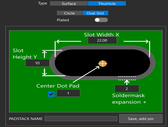
For the case of thru holes, there will be two tabs, Circle and Oval slot, as follows.
Plated, Oval Slot
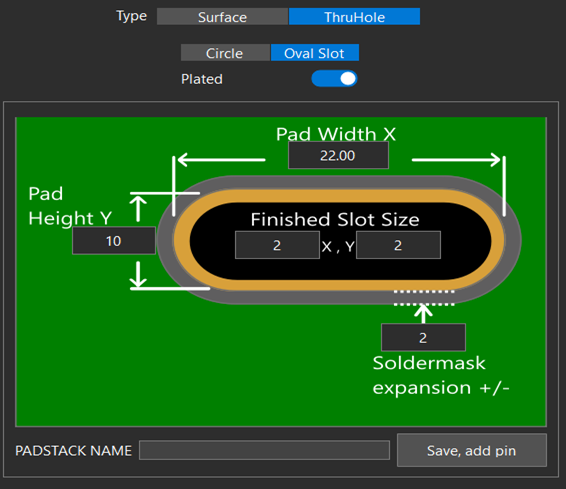
Non-Plated, Oval Slot, Center Off
Non-Plated, Oval Slot, Center On
Using the Add Pin Widget
Once you create a padstack, using any of the three methods (by searching padstacks, with the Padstack Wizard, or with the padstack editor), the add pin command becomes active and you can specify pin parameters, as follows: 
You can enter the details above, after which the pad will get attached to the cursor, and you can place the pin on the canvas. For example, if you enter the following details, then based on the inputs provided below, the pin placement is as follows: 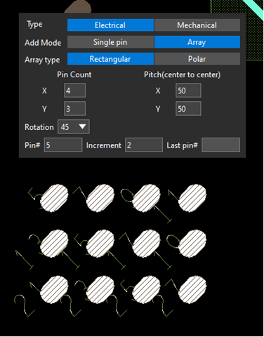
If the array type is Polar, you see the following available parameters: 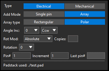
If your chosen add mode is Single pin, the Rectangular and Polar array types are unavailable, as shown below: 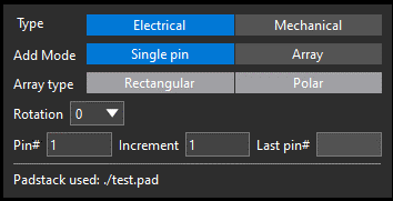
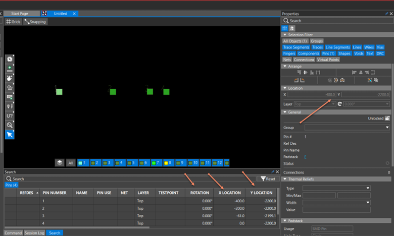
Editing Pin Locations
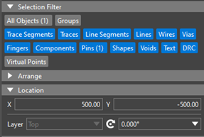
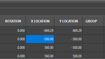
You can edit the location and rotation of one or multiple pins in the Properties panel and the search table. To do so, you first need to ensure that the location fields along with the rotation field in both the Property panel and the search table are editable.
Importing a DXF File in OrCAD X Presto
You can import a .dxf file to build a symbol.
In the Footprint Editor, choose ECO – DXF Import. 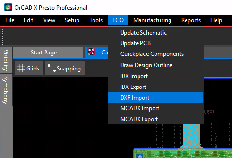
By default, the Layer conversion file field empty. You can choose a .cnv file with the browse button (...) or create one with Edit/View layers. 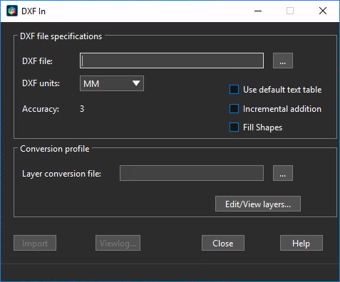
Creating Footprints from Templates
OrCAD X Professional enables you to choose templates from which you can generate footprints and 3D models.
You can choose among templates and options to see the footprints and (once generated) 3D views. You can then refresh, edit, alter, and regenerate the necessary footprints, relevant pads, and files.
To begin, choose File – New – Template based footprint. 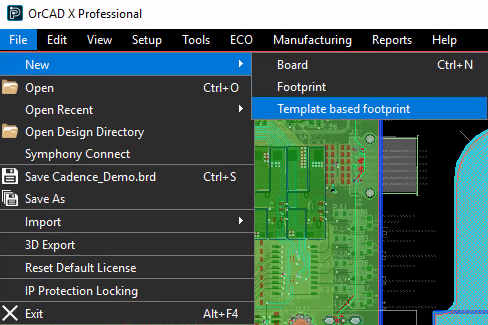
A newly-created template file opens immediately in the canvas. 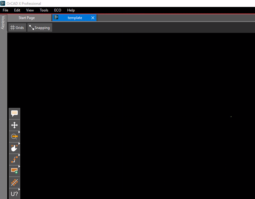
This is followed by the Footprint Generator window. 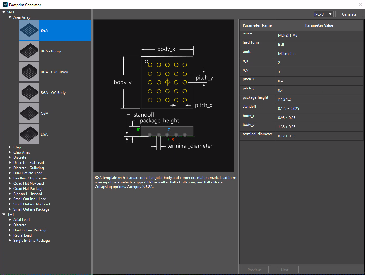
The Footprint Generator window lets you choose the type of template you want to generate, and enables you to choose which predefined IPC type (IPC-A, IPC-B, or IPC-C) you want to use.
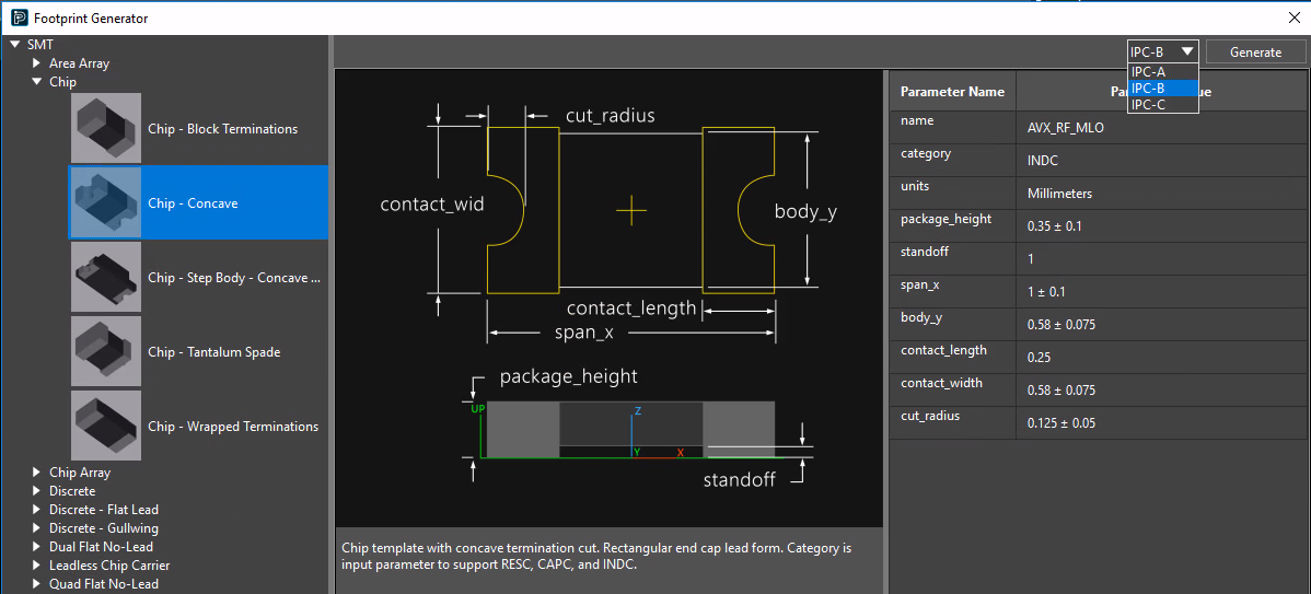
And you can also change any of the parameter values. 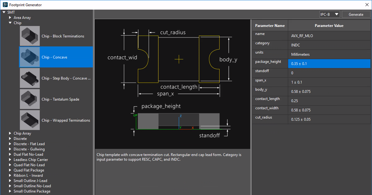
When all settings are as you want them, click the Generate button at top right.
You can always change parameters and click Generate again to re-generate the footprint according to your updated template specifications..
Generate creates the following:
- Padstacks (in the pad path)
- A DRA file (in the PSM path)
- A PSM file (in the PSM path)
The generated footprint will have the ACIS model attached to it. You can extract the STEP file from the generated footprint, as follows, from the PCB command line: 3d_model_export model -d
You can then load your generated symbol into a board, where—among other things—you can toggle between 2D and 3D views.
View the next document: 04 - Getting Familiar with User Interface of OrCAD X Presto
If you have any questions or comments about the OrCAD X platform, click on the link below.
Contact Us