03 - Working with Projects
Creating a Project
A project file (.OPJ) is a container for the design file (.DSN). There is only one design file in a project. The project file stores pointers for interacting with the design file, other referenced files, and outputs reports associated with the design file. The project file can also contain libraries, VHDL files, and information from the various dialog boxes accessible from the Tools menu.
When the project is first created, the project manager creates a design file with the same name as the project. It also creates a schematic folder within the design file, and a schematic page within the folder. You can create a new design to replace the design created by the project manager.
Creating a New Project
To create a project, do the following:
-
Choose File – New.
The New Project dialog box appears.
-
In the Name text box, specify a name for your new project.
Do not specify characters such as ( . \ / : * ? " < > | ) in the project name when creating a project or renaming a project using the Save As dialog box. Only lowercase and alphanumeric characters, hyphen and underscore are allowed in project names. - In the Location field, specify the path where you want the new project files to be saved, or use the Browse button to locate the directory.
With the Use Workspace check box selected, the Location box shows the pre-seeded workspace path, which cannot be edited. This option is selected by default and it is used to save only the workspace-based projects.You cannot manually select the workspace path to store a project. - Choose another location to create a non workspace-based project,
To move an existing local project to the workspace, use the File – Add to Workspace menu command.
- Select the Enable PSpice Simulation check box if you intend to include simulation capabilities in your PCB design.
- Click OK.
A new project is created and a blank schematic page is displayed.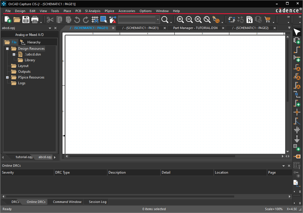
Setting up New Project for Simulation
If you select the Enable PSpice Simulation check box, in the New Project dialog box, the Create PSpice Project dialog box appears. 
- Select one of the two options:
- Create based upon an existing project
If you select this option, choose a project file (.OPJ) from the drop-down list or the Browse button. PSpice provides a set of design templates covering basic electronics circuits and SMPS topologies. These design templates cover a range of analog, digital, and mixed designs. You can use the design templates, which are a combination of design and simulation profiles, as a starting point for new designs. These templates are also suitable for learning and demonstration purposes.
You can click Browse to locate and open any of the available templates. The templates are available at:<installation_directory>\tools\capture\templates\pspice - Create a blank project
By selecting this option, you create a new project that can be simulated in PSpice AD.
- Create based upon an existing project
- Click OK to create the new project directory and open the schematic page editor.
Setting up an Existing Project for Simulation
A design created without selecting the Enable PSpice Simulation option in OrCAD X Capture can still be simulated by PSpice. The basic process involves setting up a simulation profile and preparing the parts for simulation as described in Creating Design for Simulation.
Setting Project Preferences
You set project preferences in the Preferences dialog box. The settings in the Preferences dialog box determine how Capture works on your system. These settings persist from one Capture session to the next because they are stored in the Capture initialization (.INI) file on your system. If you pass projects to others, the preference settings are not inherited. You can set themes, colors, grid display options, pan and zoom options, and so on to suit your requirements. The settings are retained even if you work on a project that was created on another system.
Setting Theme for Application and Schematic
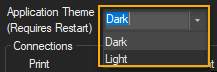
OrCAD X Capture opens in a dark theme by default. You can set the theme from the Preferences dialog box for both the application and the canvas (schematic page).
To change the application theme, do the following:
- Choose Options – Preferences.
The Preferences dialog box is displayed.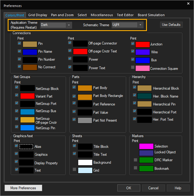
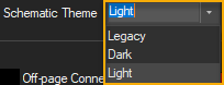
- From the Colors/Print tab, select the theme for the application and the schematic from the respective drop-down lists.
-
Click OK.
The standard Windows operating system dialog boxes do not follow the application theme when launched from Capture.
Setting Colors for Objects on the Schematic Page
You can set up colors for objects, such as off-page connectors, hierarchical blocks and ports, text, title blocks, and so on, and specify which objects will be printed or plotted. You can also change the background color and the color of the grid.
You control the color in which schematic page objects display from the Colors/Print tab in the Preferences dialog box.
- Choose Options – Preferences.
- Select the Colors/Print tab.
- Click the color for an item.
The color palette window opens. - Select a new color.
- Click OK.
Graphics objects, such as lines, polylines, and arcs use the colors specified in the Miscellaneous tab. If the color options in the Miscellaneous tab are set to Default, Capture uses the color specified for graphics in the Colors/Print tab.
Controlling the Grid Display
You can control the grid display by selecting either dots or lines for the grid and specifying whether to display or print the grid. You can also choose to have the pointer snap to grid as you place objects. These options can be set independently for the schematic page editor and the part editor.
Grid spacing is expressed as a fraction of pin-to-pin spacing, as follows:1/n
where,n is an integer with a value of 1, 2, 5, or 10
For example, a setting of 1/2 specifies that the grid spacing on the schematic page is set to exactly half the specified pin-to-pin spacing.
You can choose between displaying a grid independently in the schematic page editor or the part editor, and displaying the grid with dots or lines. You can also specify whether the pointer snaps to grid in each editor. Additionally, the drawing objects, like Line, Polyline, Text, Rectangle, Ellipse, Arc, and Picture can also be placed on fine grid.
For the schematic page editor and the part editor, you can specify:
- Whether to display the grid.
- Whether the grid uses dots or lines.
-
The grid spacing—the space between each point on the grid.
-
Whether the pointer snaps to grid as you place objects.
To control the grid display, do the following:
- Choose Options– Preferences.
- In the Preferences dialog box, select the Grid Display tab.
- Select the grid style and spacing, and click the Displayed or Printed option to change the visibility.
or
Choose View – Grid to set grid visibility only.
The visibility of the grid can be toggled. -
To change snap to grid, in the Grid Display tab, select or clear the Pointer snap to grid option.
By default, the pointer snaps to the grid for connectivity and drawing objects. - Click OK.
Customizing Placement and Movement of Objects
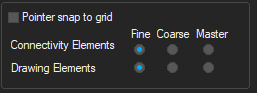
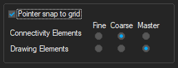
You can customize the placement and movement of connectivity objects, such as parts and symbols, and drawing objects, such as Line, Polyline, Text, Rectangle, Ellipse, Arc, and Picture, on coarse and fine grid in the schematic editor. You can use the options provided in the Grid Display tab of the Preferences dialog box to complete this task.
- These settings apply only to the schematic page grid; not to the part and symbol grid.
- The settings are saved in the
CAPTURE.INI file and it is used whenever you start the next Capture session.
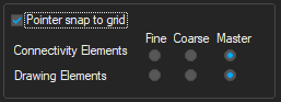
The connectivity and drawing objects can be individually configured to follow either a coarse or fine grid. The following scenarios describe the usage of the above options:
|
If... |
Then... |
|
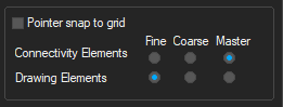
The Master option is selected for both Connectivity and Drawing Elements and the Pointer snap to grid check box is not selected:
|
The connectivity and drawing objects can be placed and moved only on the fine grid. |
|
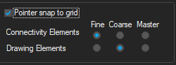
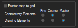
The Master option is selected for both Connectivity and Drawing Elements and the Pointer snap to grid check box is selected:
|
The connectivity and drawing objects can be placed and moved only on the coarse grid. |
|
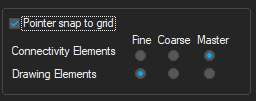
The Master option is selected for Connectivity Elements and the Fine option is selected for Drawing Elements and the Pointer snap to grid check box is not selected:
|
The connectivity and drawing objects can be placed and moved only on the fine grid. |
|
The Master option is selected for Connectivity Elements and the Fine option is selected for Drawing Elements and the Pointer snap to grid check box is selected:
|
The connectivity objects can be placed and moved on the coarse grid and the drawing objects on the fine grid. |
|
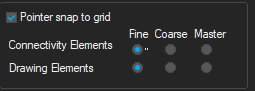
The Fine option is selected for both Connectivity and Drawing Elements and the Pointer snap to grid check box is either selected or not selected: |
The connectivity and drawing objects can be placed and moved only on the fine grid. |
|
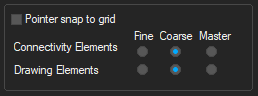
The Coarse option is selected for both Connectivity and Drawing Elements and the Pointer snap to grid check box is either selected or not selected:
|
The connectivity and drawing objects can be placed and moved only on the coarse grid. |
|
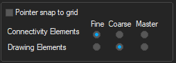
The Fine option is selected for Connectivity Elements and the Coarse option is selected for Drawing Elements, and the Pointer snap to grid check box is either selected or not selected:
|
The connectivity objects can be placed and moved on the fine grid and the drawing objects on the coarse grid. |
|
The Coarse option is selected for Connectivity Elements and the Fine option is selected for Drawing Elements, and the Pointer snap to grid check box is either selected or not selected:
|
The connectivity objects can be placed and moved on the coarse grid and the drawing objects on the Fine grid. |
|
The Coarse option is selected for Connectivity Elements and the Master option is selected for Drawing Elements, and the Pointer snap to grid check box is selected:
|
The connectivity and drawing objects can be placed and moved only on the coarse grid. |
|
The Coarse option is selected for Connectivity Elements and the Master option is selected for Drawing Elements, and the Pointer snap to grid check box is not selected:
|
The connectivity objects can be placed and moved on the coarse grid and the drawing objects on the fine grid. |
|
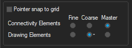
The Master option is selected for Connectivity Elements and the Coarse option is selected for Drawing Elements, and the Pointer snap to grid check box is not selected:
|
The connectivity objects can be placed and moved on the fine grid and the drawing objects on the coarse grid. |
|
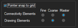
The Master option is selected for Connectivity Elements and the Coarse option is selected for Drawing Elements, and the Pointer snap to grid check box is selected:
|
The connectivity and drawing objects can be placed and moved only on the coarse grid. |


- If the selection contains both connectivity and drawing objects, the precedence is given to the option selected for Connectivity Elements.
- Ensure that the Pointer snap to grid check box is selected and the Connectivity Elements is set to Coarse while placing connectivity objects. Otherwise, your part pins may be placed on the fine grid, making it difficult to connect them properly.
- You can configure Capture to hide the grid or display it as dots or lines, and to constrain the pointer to the grid.
After you begin working on a project, you can customize its specific characteristics using the following commands from the main menu:
- Options – Design Properties when you are in the project manager
- Options – Schematic Page Properties when you are in the schematic page editor
Setting Pan and Zoom
You can define how you want auto-scrolling to work, and what the zoom factor should be. You can set these options independently for the schematic page editor and the part editor.
Pan
When you hold the left mouse button down and move the pointer near the edge of the window while, the display scrolls to a different region of the document. This change is called panning.
The Auto Scroll Percent setting determines the percentage of the screen that changes when panning.
Zoom
When you zoom in or out, the view changes by the zoom factor.
To configure zoom factor and auto scroll percent, do the following:
- Choose Options – Preferences.
- Select the Pan and Zoom tab.
- For the schematic page editor and the part editor, set these options:
- Zoom Factor: Enter an integer to indicate the magnification or reduction of the objects shown in the window when you zoom in or zoom out. This number is a multiplier for each time you zoom in or out.
- Auto Scroll Percent: Enter the percent of the window’s horizontal or vertical dimension by which the display scrolls when the pointer approaches the edge of the window with an object attached.
- Click OK.
Defining Selection Options
You can define the following selection options independently for Schematic Page Editor and Part and Symbol Editor:
- Select objects when they are completely enclosed in the selection area
- Select objects when the selection border intersects them
- The maximum number of objects to display at high resolution while dragging
To define selection options, do the following:
- Choose Options– Preferences.
- Select the Select tab.
- For the schematic page editor and the part editor, set these options:
-
Area Select: Select either Intersecting or Fully Enclosed.
If the Fully Enclosed option is selected and you select an object on a schematic page, ensure that you select the object along with its name and number. Else, the object is not selected.
- Maximum number of objects to display at high resolution while dragging: If you drag more objects than you specify here, you see rectangular placeholders for the objects as you drag them.
-
- Click OK.
Setting Miscellaneous Options
You can set the following options in the Miscellaneous tab of the Preferences dialog box:
- Specify the default fill, line style and width, and color for graphics objects.
- Define the font used in the project manager and session log.
- Render TrueType fonts with strokes (for printing and plotting).
- Set whether to enable auto recovery for your project and how often.
- Enable inter-tool communication, the method that Capture uses to communicate with other OrCAD X tools, such as PSpice and OrCAD X PCB layout.
The following table provides descriptions of the various options you can specify in the Miscellaneous tab:
| Options | Descriptions |
|---|---|
|
Fill Style |
Specifies a fill pattern to be used when drawing rectangles, ellipses, and closed shapes drawn with the poly-line tool. |
|
Line Style and Width |
Specifies both line style and line width for lines, poly-lines, rectangles, ellipses, and arcs. |
|
Color |
Specifies the color of lines, rectangles, and ellipses in the schematic page editor. This color is not the default color, but can be set to use the default color. This option overrides the default color, though changing this setting does not change the color of the objects already placed in the schematic page editor. Polylines and arcs use the default color of objects set in the Colors tab. You can change the fill style, line and width style, and color on individual objects using the Properties command on the Edit menu. |
|
Session Log |
Specifies the font for the project manager and Session Log. If you click the Font button , the Project Manager and Session Log Font dialog box appears displaying the standard Windows Font user interface for font selection. This option is neither a schematic page nor a part editor option. |
| Text Rendering |
Determines how text on a schematic page appears on the screen, and how it is printed or plotted. The Render TrueType fonts with strokes option displays text as a series of lines, connected to resemble the outlines of the corresponding TrueType letters or numbers they represent. Enabling the Fill text option causes the text outlines to be filled in. |
| Auto Recovery |
Enables auto recovery for the project and determines the time interval between saves. You can specify any interval between five minutes and 120 minutes. When the time interval is up, any design, library, or VHDL file in the project that is not saved, but modified since the last save, is saved as a temporary file with an Auto recovery is not an automatic saving feature. If you intentionally exit Capture without first saving your changes, they will be lost. Auto recovered files, the |
| Auto Reference |
Enables automatic annotating of reference designators when parts are placed. |
|
Inter-tool Communication |
Enables inter-tool communication (ITC), so that you can test and display design information using other OrCAD X tools, such as OrCAD X PCB layout and PSpice, in conjunction with Capture. Capture processes its designs faster when inter-tool communication is not selected. |
To set miscellaneous options, do the following:
- Choose Options – Preferences from the main menu.
- Select the Miscellaneous tab.
- For the schematic page editor and the part editor, set the Fill Style and Line Style and Width options.
- For the schematic page editor, set the Color option.
- Set the following options as required:
- Session Log
- Text Rendering
- Auto Recovery
- Auto Reference
- Inter-tool Communication
- Click OK.
Setting Text Editor Options
You can define which (if any) VHDL keywords are highlighted, and the font and tab settings used within the text editor.
Capture text editor options include automatic highlighting of VHDL keywords, comments, or quoted strings. You can enable or disable the highlighting feature, and set the text editor font and tab spacing.
To specify the text editor preferences, do the following:
- Choose Options – Preferences from the main menu.
- Select the Text Editor tab.
- Set the following options as required:
- Syntax Highlighting: Select the color to use to highlight VHDL keywords, comments, and quoted strings. You can choose a different color for each.
- Current Font Setting: Click Set to change the font setting for the text editor to values other than those displayed.
- Tab Setting: Set the tab spacing for the text editor.
- Select the Highlight Keywords, Comments, and Quoted Strings option to have the VHDL items highlighted in the text editor. The colors used to highlight these items are the ones set in the Syntax Highlighting group box.
This option must be enabled for Capture to use the syntax highlighting options. - Click the Reset button to reset the text editor options to the Capture default values.
- Click OK.
Setting up the Design Template
You set the design template using the Design Template or Design Properties dialog box. The Design Template dialog box determines the default characteristics of all the projects created on your system. Because a new project inherits characteristics from the current Design Template settings, it is a good idea to check the settings before you create a new project. The options that you define in the Design Template dialog box are the default settings for all new projects, and for the schematic pages you add to an existing project.
Using the Design Template/Design Properties dialog box, you can do the following tasks:
- Defining Fonts for New Designs
- Defining Title Block
- Editing Title Block
- Setting up a New Page
- Defining Grid References
- Setting up Default Hierarchy
- Setting SDT Compatibility
Defining Fonts for New Designs
You can define the fonts for schematic page objects that contain text, such as part references and values. You can define the fonts assigned to the text associated with different schematic page objects in new designs. The fonts specified here do not affect existing designs.
To assign fonts for new designs, do the following
- Choose Options – Design Template from the main menu.
The Design Template dialog box is displayed.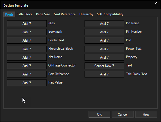
- In the Fonts tab, click the font of an item. For example, click the font for Alias.
The standard Windows font dialog box appears.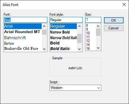
- Select a font, font style, and size.
- Click OK to close the Font dialog box.
- Click OK.
Setting up a New Page
You can specify either inches or millimeters as the unit of measure for the width and height of a schematic page, and the spacing between pins in the Page Size tab. For new projects, you can specify the default unit of measure, the default width and height of schematic pages, and the spacing between pins. The value you enter in the Pin-to-Pin Spacing text box defines how close together pins are placed in the part editor. It also defines the grid spacing, the space between grid dots or grid lines.
To set up the schematic page size, do the following:
- Choose Options – Design Template from the main menu.
- Select the Page Size tab.
- In the Units area, select the default unit of measure for new projects. This setting only affects the schematic page editor, not the part editor.
Changing from Inches to Millimeters resets the page sizes to their defaults. Therefore, if you make any changes to the standard page size dimensions, then change the units, the page size changes are not translated between the two types of units.
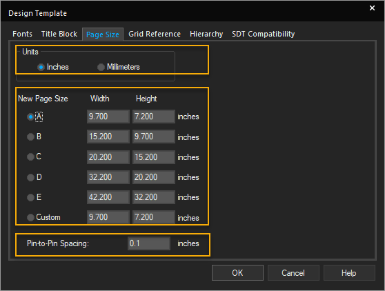
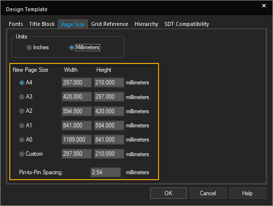
- Select the default schematic page size for new projects from the following page sizes:
-- A, B, C, D, E, and Custom, if the unit of measure is Inches.
-- A4, A3, A2, A1, A0, and Custom, if the unit of measure is Millimeters. - Specify the width and the height.
The values that you enter in the Width and Height text boxes translate to the dimensions for each page size. You cannot change these dimensions for individual schematic pages, although you can select a different page size, or define a custom size. - In the Pin-to-Pin Spacing text box, specify the default spacing between pins, grid dots, or grid lines.
You cannot change this value for existing projects or individual schematic pages.Part size will vary when copying and pasting parts between pages with different pin-to-pin spacings - Click OK.
Defining Title Block
To choose a title block and define its contents, do the following:
- Choose Options – Design Template.
- In the Design Template dialog box, choose the Title Block tab.
- In the Text group box, specify the required information to display in the title block on every page.
- In the Symbol group box, specify the path and filename of the library containing the title block.
The Library Name text box can be left blank if you are using title block from theCAPSYM.OLBlibrary andCAPSYM.OLBhas not been moved to a different directory from where it was installed. - Enter the exact name of the title block in the Title Block Name text box.
Symbol names are case sensitive and space sensitive. - Click OK.
The information added here automatically populates the title blocks on any new page.
Editing Title Block
To edit title block information, do the following
- Select the information string on the title block that needs to change.
- Choose Edit – Properties.
Alternatively double-click the string in the title block.
The Display Properties dialog box appears. - Update the values as required and click OK.
The information is updated in the title block.
OR - Select the title block, and choose Edit – Properties.
The property editor appears. - Place the cursor in the cell of the property you want to change, and enter a new value.
- Click Apply, and close the property editor.
The schematic page editor appears with the updated information in the title block.
To edit title block information on multiple pages, do the following:
- Select the design file in the project manager.
- Choose Edit – Browse – TitleBlocks.
- Click OK to dismiss the Browse Properties dialog box.
- In the Browse window, select the name or names of the schematic pages that contain the title blocks you want to edit.
- Choose Edit – Properties or press
CTRL+E.
The Browse spreadsheet editor appears. - Edit the property values for one or more schematic pages at a time.
- Click OK.
- Click Yes to confirm.
To change the display of title block information, do the following:
- Select the information string on the title block that needs to change.
- Choose Edit – Properties.
- In the Display Properties dialog box, select the Change button in the Font group box.
The Fonts dialog box appears. - Change the display properties as required and click OK to close the Font dialog box.
- Click OK.
Defining Grid References
To define the grid reference, do the following:
- Choose Options – Design Template.
You define border grid references in the Grid Reference tab of the Design Template dialog box. - Select the Grid Reference tab.
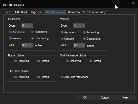
- Specify the required grid reference values in the Horizontal and Vertical group boxes.
For horizontal and vertical border grid references, you can specify:
- The number of border grid references to be displayed.
- The use of either alphabetic or numeric characters for grid reference.
- The order in which to sort grid references across the schematic page—ascending or descending.
- The width of the grid reference cells.
You can also control the visibility of the border, grid references, and title block on the screen and on the schematic pages you print. The settings are applied on new projects.
The size of the Grid Reference font is tied to the width.
- Change the visibility of the border, title block, and grid reference, by selecting Displayed to display them on the screen or Printed to print on the schematic pages you print.
- Select ANSI grid references to display the grid references in accordance with the ANSI standards.
- Click OK.
You can change these settings for existing schematic pages. Choose Schematic Page Properties from the Options menu in schematic page editor and select the Grid Reference tab in the Schematic Page Properties dialog box.
Setting up Default Hierarchy
To define the default hierarchy options, do the following:
- Choose Options – Design Template.
- Select the Hierarchy tab.
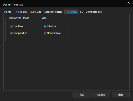
- For hierarchical blocks and parts, select Primitive or Nonprimitive.For hierarchical blocks and part instances with the Primitive property set to Default, you can specify if you want Capture to treat each block or part as primitive (cannot descend into attached schematic folders) or nonprimitive (can descend into attached schematic folders). The Primitive and Nonprimitive options only affect new projects. All hierarchical blocks and part instances that have their Primitive property set to Default will use the setting selected here.
- Click OK.
You can change the hierarchy option for existing projects using the Hierarchy tab in the Design Properties dialog box. (Choose Options – Design Properties from the project manager). This setting affects how the options on the Tools menu process projects.
Setting SDT Compatibility
You can map Capture properties to the corresponding OrCAD X Schematic Design Tools (SDT) part fields when saving a project in the SDT format. Capture uses the SDT compatibility options in the Design Template and Design Properties dialog box when you save a Capture design in SDT format. Capture sets the SDT compatibility options in the Design Properties dialog box when you open an SDT schematic folder (.SCH) file in Capture.
When you create a new design, the SDT compatibility options are inherited from the design template.
To set up the design template for SDT compatibility, do the following:
- Choose Options – Design Template from the main menu.
- Select the SDT Compatibility tab.
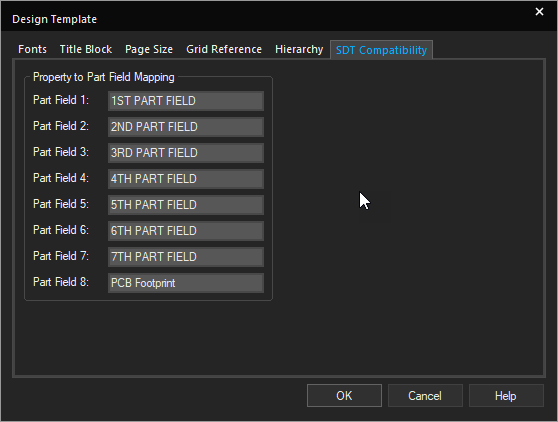
- For each Capture property to be mapped to an SDT part field, specify the part field to contain the property value in the Properties to Part Field Mapping group box.
- Click OK.
Changing SDT Compatibility Options for a Single Design
When you save a design in the SDT format, Capture uses the SDT compatibility options in the Design Properties dialog box. To change the SDT compatibility options for a design, do the following:
- With the project manager active, select the design folder.
- Choose Options – Design Properties.
- Select the SDT Compatibility tab.
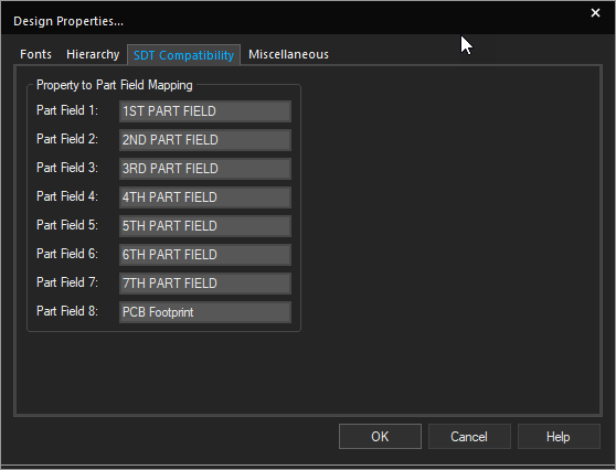
- Specify the properties to be mapped to the SDT part fields for the active design in the Properties to Part Field Mapping group box.
- Click OK.
Translating Part Fields from SDT to Capture Properties
Capture translates SDT part fields into properties. To change the user property names before translation, do the following:
- Open the
SDT.CFGfile for the design in any text editor. - Locate the lines that specify the part field names, and change them to suit your requirement.
- Save the changes, and exit the editor.
Translating Capture Properties to SDT Part Fields
You can specify properties for Capture to translate into SDT part fields by following these steps:
- Choose Options – Design Properties.
- Select the SDT Compatibility tab.
- Specify the properties to be mapped to the SDT part fields.
Connectivity Rules - Cases
Capture uses a different set of connectivity rules than SDT. The following cases explain these differences:
Case 1
The bus is split with like members connecting before and after the split.
|
Situation A |
The bus is split using a junction. |
|
SDT |
Yes |
|
Capture |
No. Buses connected through a junction must contain the same number of signals |
|
Situation B |
The bus is split using a bus entry. |
|
SDT |
Yes |
|
Capture |
Yes |
|
Situation C |
The bus is split without any visible connection, but is connected through name. |
|
SDT |
Yes |
|
Capture |
Yes |
Case 2
The hierarchical port connects to the hierarchical block through a wire.
|
SDT |
Yes |
|
Capture |
No. Wires in Capture are for single signals only. |
Case 3
The wire connects to the power symbol.
|
SDT |
No |
|
Capture |
Yes |
Case 4
Wire 1 connects to Wire 2 through a label hotpoint.
|
SDT |
Yes |
|
Capture |
No. Wires are connected only if they connect through a junction or if they share an alias. |
Case 5
The hanging wire connected to a pin causes a single node net in netlists.
|
SDT |
No |
|
Capture |
Yes |
Case 6
Buses routed through bus entries are connected to the target object.
|
SDT |
Yes |
|
Capture |
No. You should not use bus entries to route a bus to its target. Use the left mouse button to create turns in the bus route. |
Case 7
Unlike bus members are connected.
|
SDT |
No |
|
Capture |
Yes |
You can specify the properties that Capture stores in the eight SDT part fields when saving a project in the SDT format. You can also use the part fields for mapping netlists that use part field information.
Moving Objects by Drag and Drop
You can use the standard Windows drag-and-drop operation to move or copy schematic folders, schematic pages, libraries, and symbols between projects, in the project manager windows. If you wish to copy rather than move, press and hold the CTRL key while you drag the entity.
- If you are moving or copying a folder or page, verify that:
- for a folder, no Capture editor is open on any document in the schematic folder.
- for a page, that it is not open in any Capture editor.
- Open both projects in their respective project managers.
- Select the schematic folder, page, library, or symbol that you want to move or copy, then drag (pressing the
CTRLkey to copy) the selection to the destination project manager entity. - For both projects, choose File – Save All.
Documents can be dragged as indicated in the following table:
Drag from . . .
Part
Schematic Page
Schematic Folder
Design to design
X
X
Design to library
X
X
X
Schematic folder to schematic folder
X
Library to design
X
Library to library
X
X
- If you drag a part that has a part alias, the part alias also moves. In the context of dragging and dropping, a symbol behaves just as a part does—as shown in the table below, a symbol can be dragged from a design or a library and dropped in another library.
- A document that is open in an editor, or one that contains any open elements, cannot be dragged.
- If you copy or move a document from one design or library to another, you should save the destination design or library immediately. Else, you run the risk of losing the data when you open the moved document in the schematic page editor or part editor and then close the editor without saving the document.
- Deleting schematic folders, schematic pages, parts and symbols is permanent. You cannot use the Undo command to bring back deleted items from the project manager.
- If you move or copy a parent schematic folder or schematic page from one project into a second project, Capture remembers the name and directory of the file containing the child schematic folder or folders. This information is stored in the Attach Implementation dialog box for each hierarchical block and nonprimitive part.
Capture Directory Map
This section details the OrCAD X Capture install directory (<Installation Directory>\tools\capture) structure. The section also provides a brief description of the files types associated with OrCAD X Capture.
Capture directory contents
|
CAPTURE.EXE |
The Capture executable. It appears in the OrCAD X Desktop program group as Capture. |
|---|---|
|
CAPTURE.INI |
Capture's initialization file. You can specify a new location for Capture to create and modify the .INI file. Use one of the following command lines to specify the new location of the .INI file: CAPTURE -I directory\\ CAPTURE /I directory\\ where path is the directory where the .INI is located. For example: CAPTURE -I C:\CAPTURE |
|
*.EXE, *.PIF, *.DLL, and *.NT |
Executable files, program information files, and other files required by Capture. |
|
Library directory |
Contains the Cadence-supplied library files (.OLB), including the CAPSYM.OLB symbol library. |
|
Netforms directory |
Contains the netlist format files used by Capture. |
|
Samples directory |
Contains sample designs. |
Capture file types
|
*.BCF |
Binary SDT configuration file, used in translation. |
|
*.BOM |
Bill of materials report file. |
|
*.CFG |
SDT configuration file, used in translation. |
|
*.CIR |
SPICE netlist file. |
|
*.DBK |
Design backup file. |
|
*.DRC |
Design rules check file. |
|
*.DSN |
Design file. |
|
*.DSF |
VST Model netlist file. |
|
*.EDN |
EDIF netlist file. |
|
*.ERR |
DSN2MNL error text file. |
|
*.EXP |
Export property file. |
|
*.INC |
Bill of materials include file. |
|
*.INF |
VST file. |
|
*.INS |
Netlist creation file. |
|
*.LIB |
Layout or SDT library file. |
|
*.MAP |
SPICE map file. |
|
*.MNL |
Layout netlist file. |
|
*.NET |
Netlist file for most netlist formats. |
|
*.OBK |
Library backup file. |
|
*.OLB |
Library file. |
|
*.OPJ |
An OrCAD X project file. It contains references to all other files included in the project. |
|
*.PIP |
Netlist creation file. |
|
*.PLD |
OHDL netlist file. |
|
*.RES |
Netlist creation file. |
|
*.RPT |
Update properties report file. |
|
*.SCH |
SDT schematic folder file. |
|
*.SWP |
Gate and pin swap file. |
|
*.TXT |
Session log text file. |
|
*.UPD |
Update properties file. |
|
*.V |
Verilog netlist file. |
|
*.VHD or *.VHO |
VHDL file. |
|
*.XNF |
XNF netlist file. |
|
*.XRF |
Cross reference file. |
Opening a Project
After you create a project in Capture, all library and schematic information defined in the project, as well as any other included files, are recognized as part of that project. When you open the project, all such data is automatically associated with the project.
To open an existing project, do the following:
- Choose the File – Open menu command.
The Windows standard Open dialog box is displayed. - If the project you want to open is not listed in the File name text box, do one or more of the following:
- In the Look in drop-down list, select a new drive or directory.
- In the File name text box, enter a part of the file name—you can use the standard "*" and "?" wildcard characters.
- Select the project or type the name in the File name text box, then click OK.
The project opens in a project manager window.
Shortcut
Toolbar: 
- To open a recently used project, from the File menu, choose the project either by name or by number.
The project opens in a project manager window.
Ways to Save in Capture
When the project manager window is active, you can save a new or existing project, design, or library. The File – Save menu command saves all the open documents referenced by the project, as well as the project itself.
It is recommended that except for occurrence properties, the schematics of externally-referenced libraries and designs are not edited, but viewed as read-only designs. Trying to edit and save these designs from within your schematic can introduce errors such as duplicate reference designators and other problems.
When saving schematics with externally-referenced libraries or designs, occurrence properties are saved but altered instance values are not. If you want to change externally-referenced libraries or designs you should first close the referencing design. Then, open the referenced library or design, make the necessary changes, and save and close the referenced library or design. At this point, you can reopen the original design and reference the modified design.
When you save a design or project created using an earlier release, the database format for the design or project is updated for any changes in the new release. However, only opening the design or project does not result in changes.
The Save As command saves files depending on what you have selected in the project manager.
- If one or more designs or libraries are selected, you are prompted to save each file in turn.
- If no top-level folders (Design Resources or Outputs) are selected, and items other than designs or libraries are selected, the Save As command is unavailable.
- If no designs or libraries are selected in the project manager, you are prompted to save the project.
When you use the Save As command, you are prompted to choose the file type from the Save As Type list in the Save As dialog box. You can choose to save the file in the current design database schema version or in a schema version that is one version prior to the application version you are currently using.
Saving in Capture
The changes you make to a schematic page are temporary until you save the page or the project to disk using one of the save commands of the File menu. If you save one schematic page, all of the pages in the schematic are saved. If you save a project while you have several pages open in schematic page editor windows, changes you have made to any of them are saved as well as any changes made by the Capture tools. You can save a new or existing project, schematic page, design, or library wth the project manager window active. The File – Save menu command saves all the open documents referenced by the project, as well as the project itself.
To save a new design or library, do the following:
- With the design or library selected in the project manager, choose File – Save.
The Save As dialog box displays. - Enter a name for the design or library in the File name text box.
- Specify a location.
- Click Save.
The design or the library is saved, and the project manager remains open. When you close the project, Capture prompts you to save the project file.
To save an existing project, do the following:
- In the project manager, select the Design Resources or Output folder.
- , Choose the File – Save menu command.
The project is saved, and remains open in the Capture session frame.
When you save a project, you save all the files residing in the project. If you have several pages open in schematic page editor windows, changes you have made to any of them are saved. In addition, changes made by the Capture tools are saved to disk.
To save a single project, choose File – Save with the project manager in focus.
.DBK file extension. When you save a library, Capture automatically creates a backup with a .OBK file extension. If you save only a schematic page or a part, no backup is generated.A Capture a design file (.DSN) is always accompanied by a project file (.OPJ). Each time you use the File – Save As menu command to save a design file to another name or directory, you also need to save the project file using the File – Save As menu command. The following process saves a .DSN file and a .OPJ file into the same directory, so you can continue editing the current project without altering the original files.
To save a project file along with the design file to a new location, do the following:
- In the project manager, select Design Resources or Outputs.
- Choose File – Save As or File – Save Project As.The Save Project As dialog box opens.
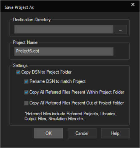
- Specify the destination directory and edit the project name, if required.
- In the Settings section, specify whether you want the design to be copied to the new location of the project.
- Also, specify whether:
– The design needs to be renamed to match the project name
– All the referenced files within the project folder need to be copied
– All the referenced files lying outside the project folder need to be copied - Click OK.
Shortcut
Toolbar: 
Closing a Project
When the project manager window is active, you can close a project without quitting Capture. Alternatively, you can close and save your project as you quit.
To close a project, choose File – Close.
A dialog box displays prompting you to save or reject the changes you made.
View the next document: 04 - Managing Workspaces
If you have any questions or comments about the OrCAD X platform, click on the link below.
Contact Us