02 - OrCAD X Capture Interface
OrCAD X Capture is a graphical user interface based application used for schematic design. This application provides you with aa large set of user-friendly tools and features to easily create your schematic design. It also has a well-defined work area that ensures you can work on your schematic design in the most optimized manner.
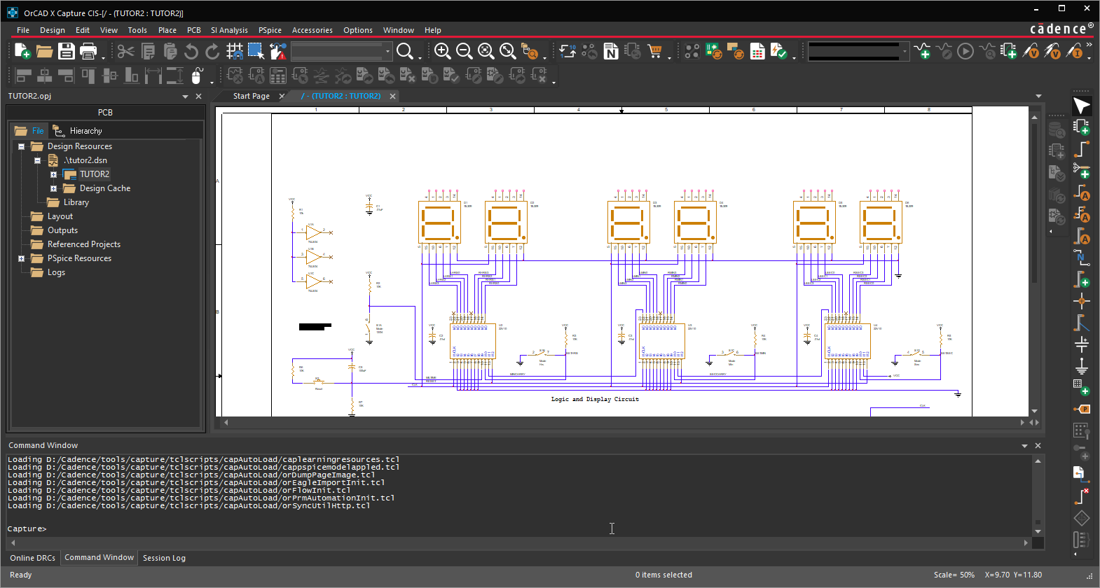
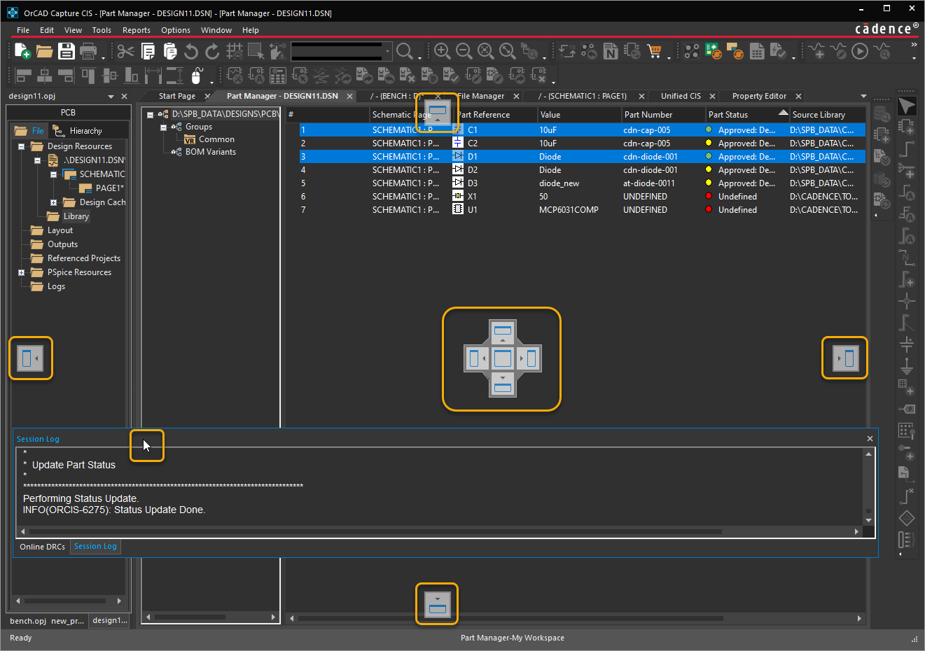
- The project manager provides a hierarchical (Windows) File Explorer type access to the resources in an OrCAD X Capture design.
- The schematic page and part editors provide a consistent and easy way to create and modify pages and parts that you require to build your design.
- The Session Log window logs the application messages.
- The Online DRCs window checks and lists the violations of design rules as you create or update the schematic design. When you double-click the violation message, Capture opens the file that contains the error and places the cursor at the location of the error. These files include netlists,
CDS.LIB,HDL.VAR, and VHDL or Verilog models. - The user interface also includes a set of menus that contain menu commands that you use to perform various operations in Capture. In addition to the menus, Capture also provides a set of toolbars that provide shortcuts to many of the commonly used commands.
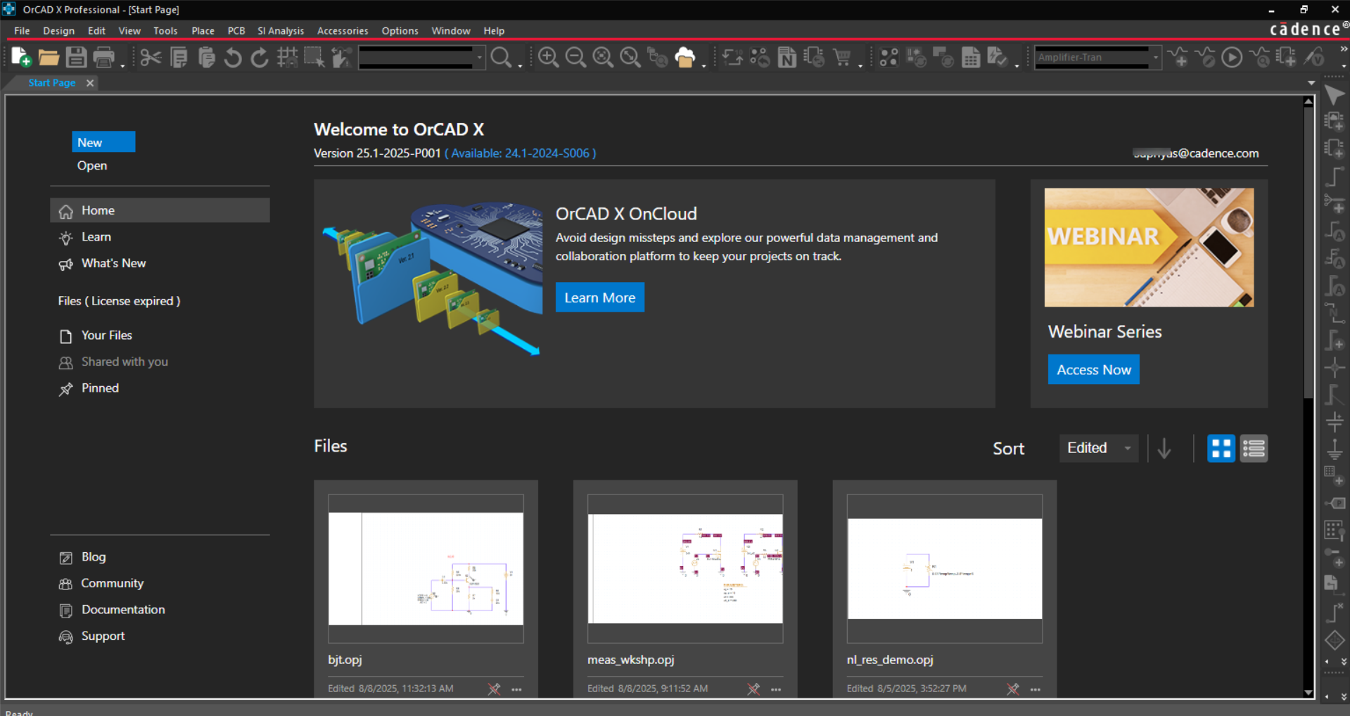
OrCAD X Capture Start Page
When you open OrCAD X Capture, you see a content-rich, well-organized Start page. From the Start page you can access a variety of information about Capture including links to informational websites, blogs, user forums, and video walkthroughs. You can also find links to documentation and Cadence Support site on this page. The Start page provides access to all the Capture projects available on your local system, on the OnCloud server (workspace), and on all the shared workspaces to which you have access.
From the Start page, you can also view the version of OrCAD X Capture installed on your system and find a link to download and install the latest available version. To download and install the latest version, launch Cadence® Download Manager or visit the Downloads site.
To connect to the OnCloud server and access the workspace-related features, you need to supply verified login credentials. Use the Login button on the Start page to log in to the OnCloud Server.
If you select OrCAD X Standard, OrCAD X Professional, or OrCAD X Professional Plus, you need to specify your login credentials. to connect to the OrCAD X OnCloud server.
- Click the Login button at the top-right corner of the Start page.The Cadence Login dialog box is displayed.
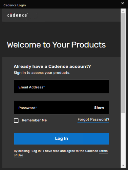
- Specify the email id and password provided by Cadence and click Log In.The login credentials are submitted to the Cadence OnCloud server for authentication.
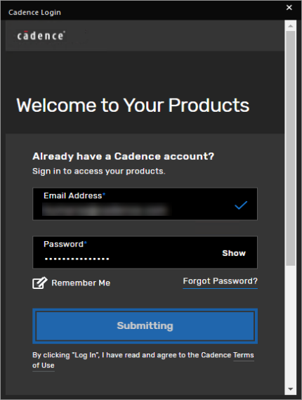 As an added layer of security, the Cadence OnCloud server uses Multi-Factor Authentication (MFA) to prevent any unauthorized user from accessing your account. You are prompted to request for a verification code, which is sent to your registered email id.
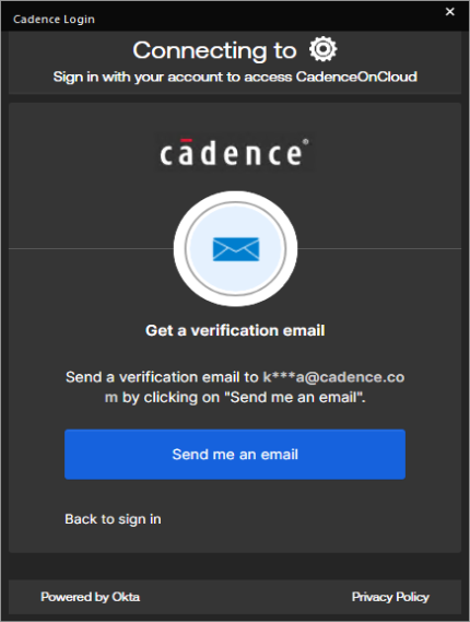
- Click the Send me an email button.You receive an email with the verification code.
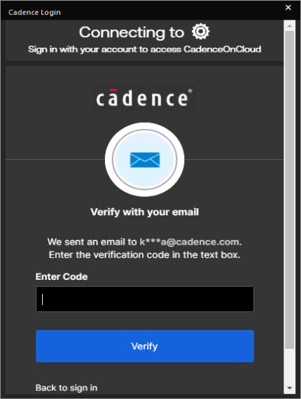
- Enter the verification code and click Verify.
After the login credentials are verified, the Start Page displays the user id at the top-right corner and populates user-specific information. 
With the OrCAD X Professional Plus (POX300 Plus), OrCAD X Professional (POX200 Pro) and OrCAD X Standard (POX100 Standard) licenses, you can seamlessly access your Capture designs, libraries, components, and other design elements across devices based on your OrCAD X OnCloud login credentials. For example, you can start creating a Capture project on your laptop using the desktop application and then continue working on the same design files from a different device. By default, the designs are created at the following location in the user's %HOME% folder: %HOME%\cdssetup\workspace For the same login credentials, design data is automatically synchronized with OrCAD X OnCloud across devices to maintain consistency. Using File Manager you can manage all the project and library files stored on the OnCloud server.
Sections in Start Page
| Section | Description |
|---|---|
| Installed Version No, | The version of OrCAD X Capture installed on your system. |
| Latest available version on Downloads | Link to the available newer version. Click to download and install the latest version. |
| Login id | Login/Email id of the currently logged in user. |
| Login button | Log in to use the OrCAD X OnCloud features. |
| New File | Create new project. |
| Open | Open an existing project. |
| Home | Learn and Explore more about OrCAD X Capture and related products. |
| Learn | Recent videos in various categories, including Schematic, PCB Layout, Library, Data Management, PSpice. Search for specific videos. |
| What's New | Videos based on new features in the release. |
| Files (License Expiry: <no. of days>Days Left) |
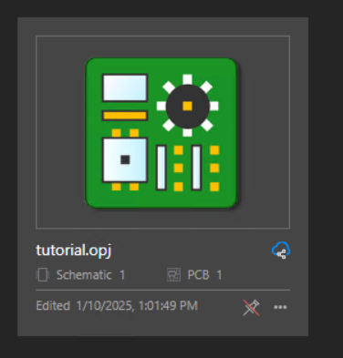
Your Files - All the files in your My Workspace. Shared with you - All the files in the shared workspace. Pinned - Any file you pin appear in this section. You can pin frequently-used projects for easy access. In the mentioned screenshot, Schematic 1 indicates the number of schematics in the project file. PCB 1 indicates the number of board files associated with the project.
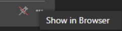
Click Show in Browser to open the file location in the Explorer view:
|
| Blog | Opens the PCB Design and Analysis blog featuring posts on OrCAD X products. |
| Community | Opens the user forum about OrCAD X products on the Cadence community page. |
| Documentation | Opens product help documentation in Cadence Doc Assistant. |
| Support | Provides information related to the Cadence contact or regional Cadence Channel Partners. |
Enabling or Disabling Start Page
You can disable the Start Page from appearing when the tool launches. To do so, use one of the following methods. However, after every hotfix, the Start Page will appear once before these settings apply.
-
Add the following statement in the Preferences section of the
Capture.inifile:EnableStartPage=False
-
Enter the required command in Command Window of Capture.The associated TCL command to disable the Start Page is:
SetOptionBool EnableStartPage FALSE
The associated TCL command to enable the Start Page is:
SetOptionBool EnableStartPage TRUE
Project Manager
The project manager window appears as a floating, dockable, or tabbed panel on the left hand side of the OrCAD X Capture application window when you open or create a project. The project manager window displays and organizes all the resources used in a project throughout the design flow.
These resources include schematic design files, part libraries, netlists, VHDL or Verilog models, simulation models, timing files, stimulus files, layout files, and any other related information. You can access all the files from within the project manager window.
Project Manager Tabs
The project manager provides the following tabs to view a project:
- File
- Hierarchy
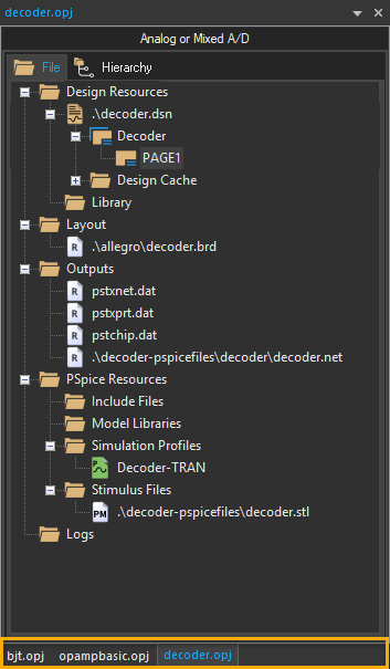
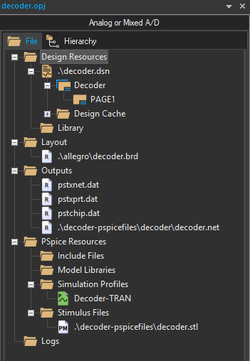
| File |
|---|
|
The File tab is organized into folders and displays all the files included in the project including the design file, the libraries, VHDL models, netlists, schematic pages, simulation models, stimulus files, or any other files that contain information related to the project. |
|
|
|
The files in the File tab of the project manager are organized in related folders including Design Resources, Layout, Outputs, PSpice Resources, and so on. The shortcut menu on each of these folders provides the commands to perform the following functions:
Design Resources The Design Resources folder contains the design (
The shortcut menu for the Design Resources folder provides an additional command, Remove PSpice Resources, to remove the simulation profile associated with the current project in case of a non-PSpice project. |
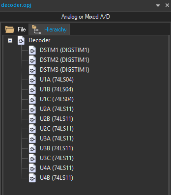
| Hierarchy |
|---|
|
The Hierarchy tab shows the hierarchical relationship among the various design modules. |
|
|
|
A design module is a structural block, typically represented as a distinct hierarchical entity, that defines the functionality of a particular portion of your design. A design module in Capture can be a VHDL or Verilog model or a schematic folder. Each instantiation of a particular module appears in the Hierarchy tab as part of a hierarchical tree. The hierarchical view of the design is derived from the files that exist in the Design Resources folder in the File view. |
Project Manager Behavior
- Within the project manager window, you can expand or collapse the structure you are viewing by clicking the plus or minus sign to the left of a folder. A plus sign indicates that the folder has contents that are not currently visible; a minus sign indicates that the folder is open and its contents are visible, listed below the folder.
- When you double-click a schematic folder, Capture displays the schematic pages within that folder. If the folder is a VHDL model, Capture displays each defined entity in that model. If the folder is a Verilog model, Capture displays each defined module in the model.
- When you double-click a schematic page, a VHDL entity, or Verilog model, that object is opened in an associated editor. For example, double-clicking a VHDL entity opens the VHDL model file at the location of that entity definition in Capture's VHDL editor.
- Each project you open has its own tab within the project manager window. If you close the project manager window, the active project tab is closed.
One Design for One Project
Each project can contain only one design (.DSN). The design may consist of any number of schematic folders, schematic pages, or VHDL or Verilog models, but must have a single root module. The root module is the module that is defined as the top-level entity for the design. That is, all other modules in the design are referenced within the root module.
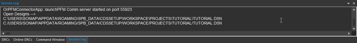
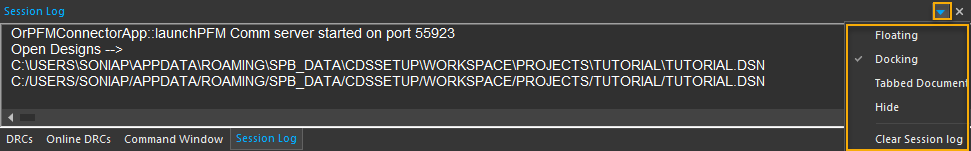
Session Log
The OrCAD X Capture Session Log window or output window contains a record of events that occur during the current session of the tool.
The Session Log window also includes results and messages from Capture utilities available from the Tools menu.
The following table lists the operations you can perform related to the Session Log window:
| Operations related to Session Log | Description |
|---|---|
| Show | To show the Session Log window, choose View – Session Log Window. Alternatively, choose Window – 1 Session Log - Session Log. |
| Save | To save the contents of Session Log to any location on your system, click in the Session Log window and choose File – Save As. |
| Hide |
To hide the Session Log window, choose Hide from the shortcut menu in the Session Log window. |
| Clear |
Or
|
| View as |
To view the Session Log window as Floating or as a Tabbed document, choose the corresponding command from the shortcut menu in the Session Log window.
|
If Capture exits with a crash, the information in Session Log is saved as capture_crash_session.log in the %TEMP% folder, if defined. Else, it is saved in the current working directory.
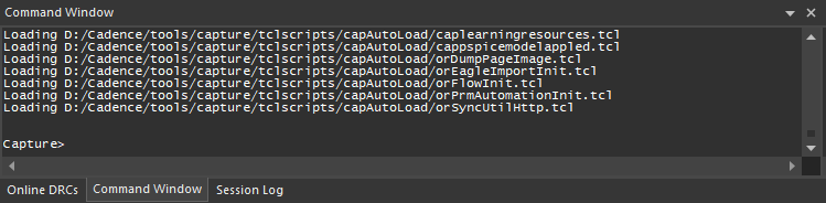
Command Window
OrCAD X Capture includes Tcl commands that are internally used when you perform tasks in the user interface. When you perform an operation (function) in Capture, the associated command is registered with the Tcl interpreter and the command is logged in Command Window.
To display Command Window, do one of the following:
- Select View – Command Window.
- Right-click any menu bar or toolbar and select Command Window.The Command Window menu command acts as a toggle to hide or display Command Window.
To clear the contents of Command Window, at the Command prompt type cls and press Enter.
Property Spreadsheet Editors
OrCAD X Capture includes three spreadsheet editors to view, edit, and add properties to the objects in a project:
Property Editor Window
The Property Editor window lets you view, edit, and add properties to the objects in a project. This window displays all the library definitions, instance properties, and occurrence properties for an object.
Using Property Editor, you can edit properties for the instances and occurrences of:
- Parts (including hierarchical blocks)
- Nets (including constituent nets within buses)
- Pins
- Title blocks
- globals
- Ports
- Aliases
The properties that appear in Property Editor depend on the object selected in the schematic page.
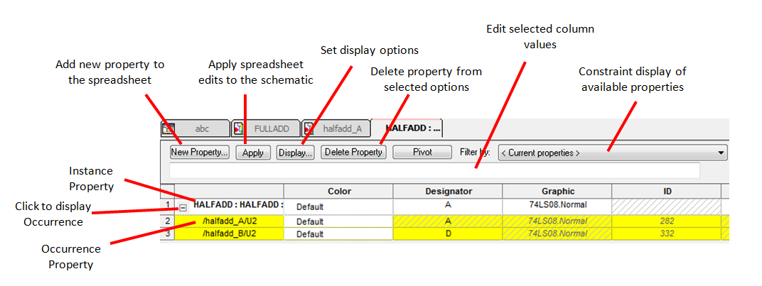
In the Property Editor window:
- Each column represents a property.
- Each row is an instance or occurrence.
- Occurrence rows appear in yellow below their associated instance row. They only appear if you expand the instance by clicking the plus sign (+) to the left of the instance name, or if an occurrence property of an object is different from the instance.
- The cells show the property values for each instance or occurrence.
- If a white cell contains hash marks, the corresponding property does not have an instance value, the library definition of the property is visible for the instance.
- If a yellow cell contains hash marks, the corresponding property does not have an occurrence value, the instance value is visible for the occurrence.
- The properties that appear depend on the object selected in the schematic page.
- The properties depend on the tab selection at the bottom of the Property Editor window. For example, if the Parts tab is active, the properties for the selected parts are displayed.
To open the Property Editor window, do the following:
- Select one or more parts, nets, pins, title blocks, aliases, or globals in the schematic page editor.
- Choose the Edit – Properties menu command.
Alternatively, you can use one of the following ways to open the Property Editor window:
- Right-click an object on the canvas and choose Edit Properties from the shortcut menu.
- Double-click an object on the canvas.

When editing properties in Property Editor:
- Property values that are applied to instances are visible on all the occurrences of those instances, unless a specific value is explicitly set for the occurrence, independent of the instance value for a particular property.
- Occurrence property values override instance property values.
- When you delete an instance property, that property will no longer be visible on the occurrences.
- Deleting a property value from an occurrence causes the instance property value to be visible on that occurrence.
- Library definitions are visible on the instance and occurrence of the object only if the instance or occurrence value is unedited.
The following table provides a description of the fields and buttons in the Property Editor window:
| Field | Description |
|---|---|
| New Property |
Displays the Add New Property dialog box to add a new property column or row. The new property is added to a single object if a single cell is selected or to multiple objects if multiple objects are selected on the schematic.
|
| Apply |
Applies the changes in Property Editor to the schematic page. The Apply button does not close the Property Editor window. You can also apply the changes to the schematic page by explicitly |
| Display |
Displays the Display Properties dialog box to set the display option of the selected property and its value. Using the Display Properties dialog box, you can:
You cannot display properties of an occurrence property from the Display Properties dialog box. |
| Delete Property |
Deletes an editable property from the selected object or objects. Properties that are not editable appear in italics. If you select all the cells for a property and click the Delete Property button, |
| Filter by |
Specifies a filter by which to view the objects. Use the Property Editor filters to constrain the available properties. For example:
You can view all the properties available on the objects in the Property Editor window by selecting the <Current properties> filter from the drop-down list. |
|
Column Value Editor |
Displays and lets you change the value in the selected column. As a result, you do not need to resize the column widths to be able to view values that are larger than what can be |
| Tabs in Property Editor | The tabs along the bottom of Property Editor let you edit properties specific to the objects in the selected tab. All the Property Editor tabs provide one row of property information per instance or occurrence. |
| Parts |
Displays the part properties of the selected objects. The Parts tab includes hierarchical blocks. You can use the Parts tab in Property Editor to add and delete property The Graphic property column provides the option to toggle the display of the part between Normal and Convert view. When you click the Graphic cell, a down arrow appears |
| Schematic Nets | Displays the schematic net properties of the selected objects. This tab includes constituent nets within buses. |
| Pins |
Displays the pins of the selected objects. This tab includes hierarchical pins in hierarchical blocks. |
| Title Blocks |
Displays the properties of the title block used on the schematic page. In the Title Blocks tab, you can add a property to the title block instance on a schematic page |
|
Globals |
Displays the properties of the selected ground or power symbols for simultaneous editing of multiple symbols. |
|
Ports |
Displays source symbol, source library, and type of port properties. Facilitates the simultaneous editing of the properties of multiple ports. |
|
Aliases |
Displays color, font, name, and rotation and other properties of net aliases. Use the Aliases tab to edit multiple aliases at one time. |
|
Rows and columns |
In Property Editor, each row displays an instance or an occurrence of an object. Instance rows appear with a white background. Occurrences appear in yellow below or alongside their associated instance row depending on the orientation of the spreadsheet. Occurrence rows automatically appear when one or more of the occurrence property values are different from the instance property values. You can add a value by clicking inside the cell, typing the value, and pressing |
Moving Around in Property Editor
- Roll the mouse wheel up and down to scroll through vertically in Property Editor.
-
Hold down the
CTRLkey and roll the mouse wheel to zoom in and zoom out. -
Hold down the
SHIFTkey and roll the mouse wheel up and down to scroll through horizontally in Property Editor. - Click the mouse wheel button and drag the mouse wheel:
- To the right or left in the Property Editor window to scroll horizontally.
- Up or down in the Property Editor window to scroll vertically.
Changing the Appearance of Property Editor
You can change the appearance of the Property Editor by showing or hiding columns, changing their widths, or even changing the orientation of the spreadsheet. Any changes you make to the appearance of the spreadsheet are saved to the PREFPROP.TXT file when you close the Property Editor window. The next time you open to that particular tab in that particular filter, you see the saved settings. This does not apply to any changes you make to the spreadsheet appearance while using the <Current properties> filter.
Changing the Orientation of the Spreadsheet
The default orientation of the spreadsheet is landscape as it shows properties in columns and instances and occurrences in rows. If you pivot the spreadsheet, the instances and occurrences appear in columns across the top, and properties appear in rows. This may be advantageous when the selected object or objects have several properties.
To change the orientation of the spreadsheet from the landscape (horizontal) to portrait (vertical), do the following:
- Right-click the empty cell in the top-leftmost position of the spreadsheet.
- Choose Pivot from the shortcut menu.Alternatively, Double-click the empty cell in the top-leftmost position of the spreadsheet.
Showing or Hiding Occurrence Properties
- To display all the occurrence properties with a single keystroke, press and hold the
CTRLkey while clicking on one of the plus (+) symbols in the leftmost column. - To hide the occurrence properties, press and hold the
CTRLkey while clicking on a dash (-) symbol in the left column.
Moving Columns
To move columns in the Property Editor window, do the following:
- Click the title cell of the column to be moved.
- Click the title cell of the column again and drag the column to the new location.
Sorting Columns
To sort columns in the Property Editor window, do one of the following:
- If the spreadsheet is not pivoted, double-click on the column heading to toggle the sort order between ascending and descending.
- If the spreadsheet is pivoted, that is if the orientation is portrait, right-click the column heading and choose Sort Ascending or Sort Descending.
Resizing Columns
To change the width of a column, do the following:
- Move the cursor to the right edge of the title cell of the column to be resized.
- When the cursor (down arrow) changes to a double-sided arrow, click and drag the column edge.
SHIFT key while dragging the column edge to resize all the columns to the same width. When the spreadsheet is pivoted, these changes are saved on the tab and the filter in use.Browse Spreadsheet Editor
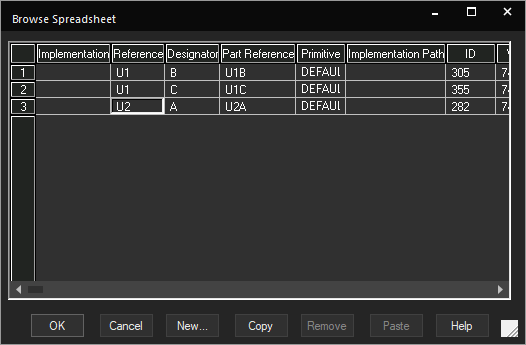
You use the Browse Spreadsheet editor to create a new property, copy values across properties, or remove a user-defined property. You can display the Browse Spreadsheet editor from project manager, schematic page editor, the part editor, or the Find Results window.
Opening Browse Spreadsheet Editor
To open the Browse Spreadsheet editor, do the following:
-
Select the schematic design or the schematic page from the project manager.
You can also edit pin properties in the Browse Spreadsheet editor when opened from the part editor and part properties from the Find Results window - Choose Edit – Browse.
- Select the required object type from the list.
- In the Browse Properties dialog box, choose the preferred mode and click OK.
When opened from the project manager, you can change the properties of the following objects:
- Parts (including hierarchical blocks)
- Nets (including constituent nets within a bus) occurrences
- Flat Netlist
- Hierarchical ports
- Off-page connectors
- Title blocks
- Bookmarks
- DRC markersThe entire design is browsed for the object type you select and a list of the objects is displayed.
- Select one or more objects from the resultant list.
- Choose Edit – Properties.The Browse Spreadsheet editor opens.
- Add a new property or edit existing properties as required and click OK.
Package Properties Editor
You can edit package properties using the Package Properties editor. The Package Properties editor is available along with the part editor when you open a part.
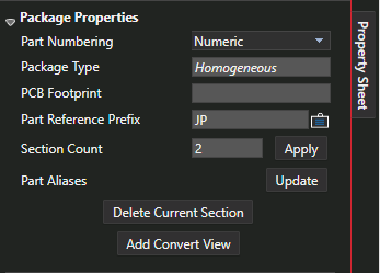
The spreadsheet displays all the package information on pins. The Package Properties editor gives you the options described in the following table:
| Field | Description |
|---|---|
| Part Numbering | Specify the numbering mode. The valid values are Numeric and Alphabetic. Numeric is the default value. |
| Package Type | Specify the type of project. |
| PCB Footprint | Specify the PCB footprint of the package. |
| Part Reference Prefix | Specify the part reference prefix. U is the default value. |
| Section Count | Enter the number of sections. The default value is 1. |
| Part Aliases | Specify any part aliases. |
| Display Property (icon) |
Specify the visibility for the property name and value. You can select from Do Not Display, Value only, Name and Value, Name Only, Both if Value Exists, Value if Value Exists. |
| Apply | Click to apply the section count. |
| Update | Click to update part alias values. |
| Delete Current Section | Click to delete the selected section. This button is disabled for a part with a single section and for a heterogeneous part with only two sections. |
| Add Convert View | Click to add a convert view. |
Component Explorer
Component Explorer is a component management system that provides an intuitive user interface to access components from various sources including Cadence-supplied libraries and content providers, without any additional overhead of creating a preferred part database and setting up an ODBC data source.
The Component Explorer interface provides a complete part authoring solution with the following functions:
- Search for components from a variety of sources and add them to schematic designs
- Create libraries by adding components from content providers
- Create new categories or templates
- Create new components in your local workspace
- Link a manufacturer part number with an existing library component
- Create shared workspaces and assign roles
- Collaborate with other team members on design projects by publishing components to shared workspaces
OrCAD X Professional (POX200 Pro) and OrCAD X Professional Plus (POX300) licenses. With these licenses you can collaborate with your team members by sharing workspaces and providing access rights on the shared workspaces. With the OrCAD X Standard (POX100 Standard) license, you can only access workspaces.Supported Functions
In the Component Explorer tab, you can view, search, and place components from the following sources:
- Cadence-supplied PSpice libraries
- CIS Part Database
- Workspaces:
- Local – Represented by the My Workspace node
- Shared – A named workspace shared with other users so that they can view and use the shared components
- Cadence-supported content search providers – SamacSys, Ultra Librarian, SnapMagic
You can directly search for components matching a specific search string. When you are connected to any of the sources in Component Explorer, you can use the following functions:
- View components and their properties
- View symbols and footprint
- View Manufacturer Part Number (MPN) details for parts in the workspace
- Place components in the design
Component Explorer Interface
- To open Component Explorer, choose Place – Component from the main menu of OrCAD X Capture.
The Component Explorer tab opens.
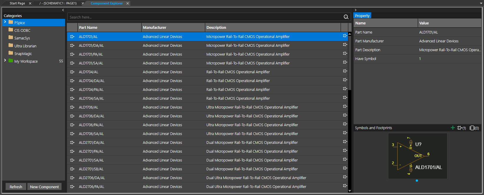
The user interface is divided into three distinguishable panes:
| Pane | Description |
|---|---|
|
Left Pane |
The left pane or the Categories browser displays a list of sources from where you can place components in the design. The Categories tree includes the following nodes:
|
| Middle pane |
The middle pane or the part browser displays the components from the node selected in the left pane. This pane also includes a Search box at the top where you can search for a component within a selected category or subcategory by specifying keywords associated with the component. You can also use search queries to perform a more specific search on the selected source in the left pane. Additionally, for the components in My Workspace, a Manufacturer Part Number table shows MPN details in the bottom of the middle pane, if they are linked to the component. |
| Right pane |
The right pane includes the Property browser that displays the properties of the component selected in the part browser. The Symbols and Footprints section in this pane displays the symbol and footprint information of the selected component in a carousel view. If a part has multiple symbols, the symbol that appears in the Symbols and Footprints view at the time of selection, is placed. |
File Manager
With an OrCAD X license, Capture design and library data in a workspace is read from OrCAD X OnCloud and the sync status is synchronized with the client. You can access workspaces using the File Manager user interface. File Manager displays the local workspace and all the workspaces shared by or with you. You can select each file and check its metadata including name, creation and modification dates, size, sync status, lock status, and so on. The complete folder structure of the projects and the designs in the workspaces are displayed just the way they appear for a project on a local disk in the project manager.
- Access File Manager from the View – Workspace – File Manager menu.
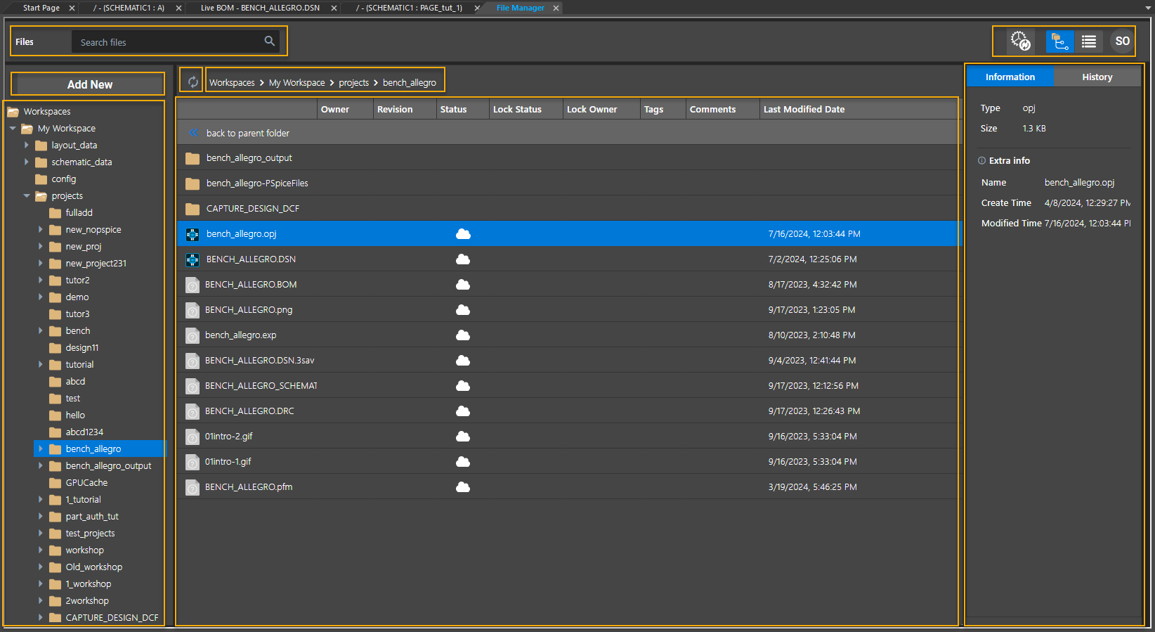
The File Manager user interface is divided into three panes:
| Pane | Description |
|---|---|
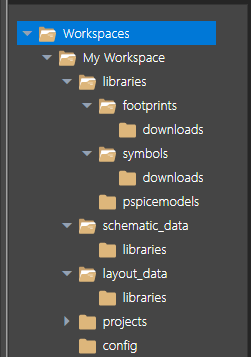
| Left Pane |
Displays a tree view of My Workspace and all the shared workspaces. All the libraries, projects, and design files in the workspace are listed here.
The libraries folder contains all the libraries-related data, such as PCB footprints and schematic symbols. All the schematic and layout files are stored in the schematic_data and layout_data folders, respectively. The projects folder contains all the projects created or stored in the OnCloud workspace:
You can create a project in the workspace or add an existing project to the workspace. A user with the Librarian role has complete access to the contents of the libraries folder. Similarly, a user with the Designer role has complete access to the projects folder containing all the design data. |
| Middle Pane |
Displays the files and folders contained in the node selected in the left pane. The metadata of the selected files is also displayed. The details listed depend on the selection in the left pane:
|
| Right Pane | Displays file information and history of revisions of a file. You can view the revision history of a file, and roll back to a specific revision. |
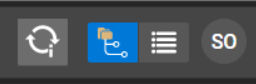
Additionally, File Manager includes the following screen options:
| UI Element | Description |
|---|---|
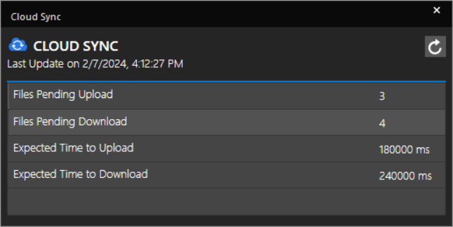
|
Cloud Sync button |
Opens the Cloud Sync dialog box that displays the sync status of the data.
|
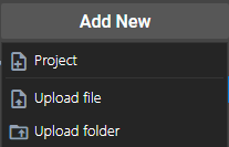
| Add New button |
Opens a menu to add a new project, upload design and library files, and upload a project folder to the OnCloud workspace.
|
| View modes |
Provides the option to view the files in the middle pane in either the Hierarchical View or Flat View mode. |
| Username |
Displays the initial two letters of the username. Moving the mouse pointer over the initials reveals the username (email id). |
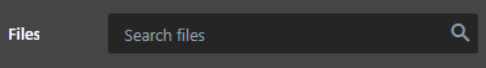
|
Files Search bar |
Searches for a specified search string in the node selected in the left pane. |
|
Breadcrumb Navigation |
Indicates the current location of the selected file. Also helps you navigate to the parent folder. |
|
Refresh button |
Reloads the selected folder in the left pane. |

Title Block
A title block provides a template to document important information about a schematic design. The information included in a title block can be generic to specific, including the design name, date of creation and modification, name and address of the organization, schematic page count, number of revisions, and so on. Capture supports two types of title blocks: default and optional. A default title block—which you specify on the Title Block tab in the Design Template or Design Properties dialog box is placed at the lower-right corner of each new schematic page. You specify the text to appear in title block fields, as well as the path and filename of the library containing the title block. This affects new projects, as well as new schematic pages in existing projects.
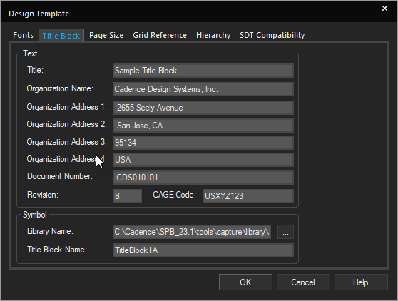
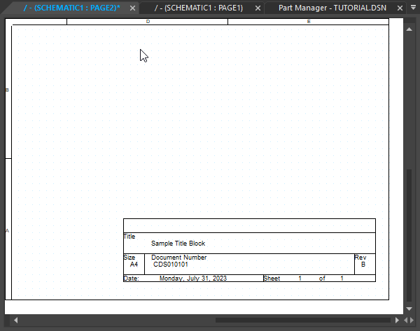
Design Template Dialog Box – Title Block Tab Schematic Page with Title Block
You may place any number of optional title blocks anywhere on the schematic page, using the Place – Title Block command from the main menu.
Default Title Block
You specify the information that goes into the default title block in the Title Block tab of the Design Template dialog box. Capture places a default title block on each schematic page, if a library and title block name is specified, and places the information you enter in the text fields in the Title Block tab into the title block. This information is also used in reports created by the commands on the Tools menu. It affects new projects, as well as new schematic pages in existing projects.
You can set the visibility of the default title block on an existing schematic page by changing the setting in the Grid Reference tab in the Schematic Page Properties dialog box. Capture provides default title block symbols in the CAPSYM.OLB library. Not all of the available default title blocks provide the same information. For example, TitleBlock0 does not provide any properties for the organization name and address, while TitleBlock5 provides the organization name property and all five of the address properties. You must specify which title block you want for the default in the Design Template dialog box.
The following table lists the default title block properties that you specify in the Title Block tab of the Design Template dialog box:
| Field | Description |
|---|---|
| Text | |
| Title | Specifies the title of the schematic page that appears in the title block placed on the page. |
| Organization Name | Specifies the name of the organization. |
| Organization Address 1 | Specifies the first line of the organization address. |
| Organization Address 2 | Specifies the second line of the organization address. |
| Organization Address 3 | Specifies the third line of the organization address. |
| Organization Address 4 | Specifies the fourth line of the organization address. |
| Revision | Specifies the revision. |
| Document Number | Specifies the document number. |
| CAGE Code |
Specifies the CAGE Code. CAGE is an acronym for Commercial and Government Entity. It is a numeric code provided by the federal government to its suppliers. This code is used in the title block of a schematic page. |
| Symbol | |
| Library Name | Specifies the name and path of the source library that contains the title block symbols. |
| Title Block Name | Specifies the name of the symbol for the title block to be used from the source library. |
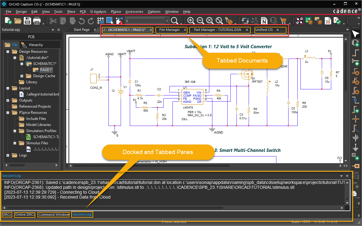
User Interface Customizations
In OrCAD X Capture, schematic pages, parts, projects, instances of part manager, open in separate panes. You can open as many panes as supported by your computer resources. For example, if you wish to work with three schematic pages or three parts, you can open each in its own pane. All resources opened from a project are displayed as horizontal tabbed documents in the canvas area. By default, all panes displaying any kind of output are at the bottom of the application. If multiple panes are open in the output window, they are displayed as docked and tabbed panes.
UI Panes
UI panes in the canvas area are displayed as horizontal tabbed documents or panes. These panes, which have labels, are not reduced in size or resolution when the number of open panes increases. They can also be moved and arranged as desired.
- Use the right-click shortcut menu commands for each pane to display the planes in the desired way, Floating, Docking, or Tabbed Document.
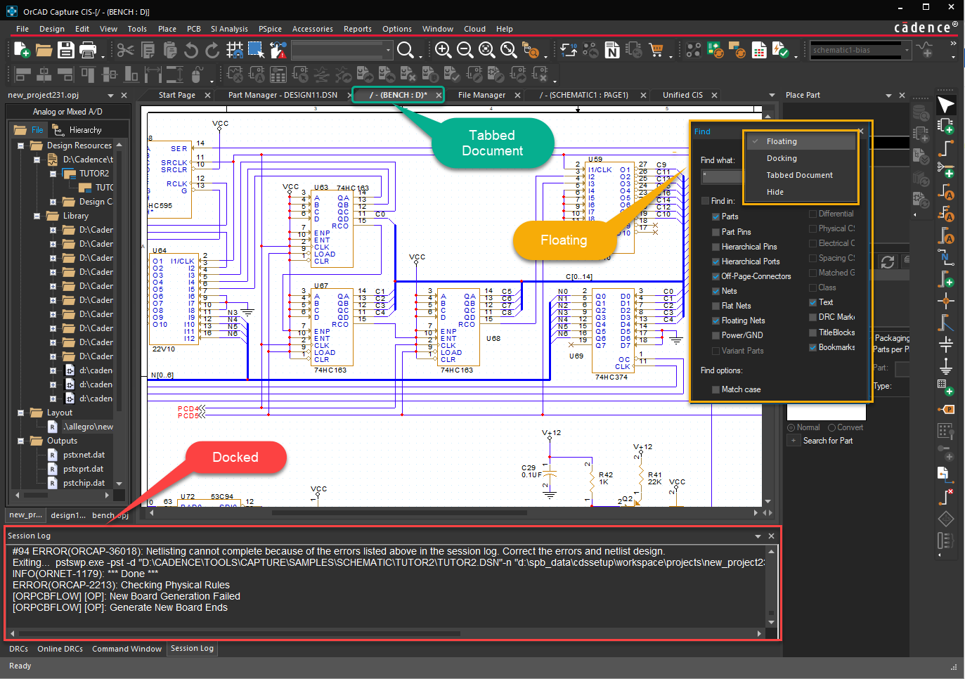
- Drag and drop panes to move them around using the docking markers as shown in the following figure:
Multiple Monitor Support
You can drag a tabbed document and display it on another monitor as shown in the following figure. In this example, the active project is dragged and becomes a separate window, which can be displayed on a different monitor:

Schematic Pages
You can open a new instance of the currently active schematic page window. You can then scroll the two windows to different positions in the schematic and view the data.

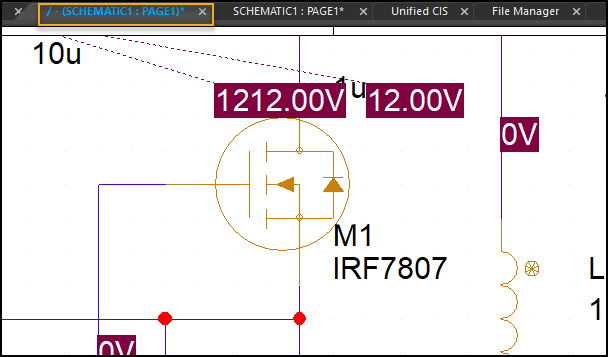
Schematic: Page1 - Window 1 Schematic: Page1 - Window 2
Both the windows provide a simulatenous view of the schematic. Any change you make to the schematic in one window is reflected in the other window as well.
- To open a new window on the active schematic page, choose Window – New Window.
- To open a recently opened schematic page, from the Window menu choose the desired schematic page.
-
To close all the open schematic pages, choose one of the following commands from the Window menu:
- Close all Tabs of Active Project
- Close all Tabs of Active Project Except Current
- To close all the windows, choose Window – Close All Windows.
Project Manager
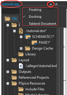
When you work simultaneously on several projects, each opens in its own project manager window.

You can right-click the title bar of project manager and set it as Docked, Floating, or Tabbed.
Output Display
The common area at the bottom of the application area where you can view any kind of output: commands, results, messages, errors, or warnings. This output is displayed in the following panes:
- Command Window
- Session Log
- Online DRCs
- DRCs
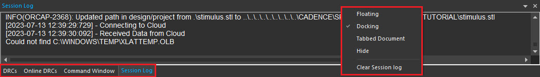
You can right-click the title bar or the tab name of an output pane and choose the option to set it as floating, docked, or tabbed (document) panes.
Navigating in Tabbed Panes
All the open documents are tabbed panes. You can right-click the tabs to save or close the panes.
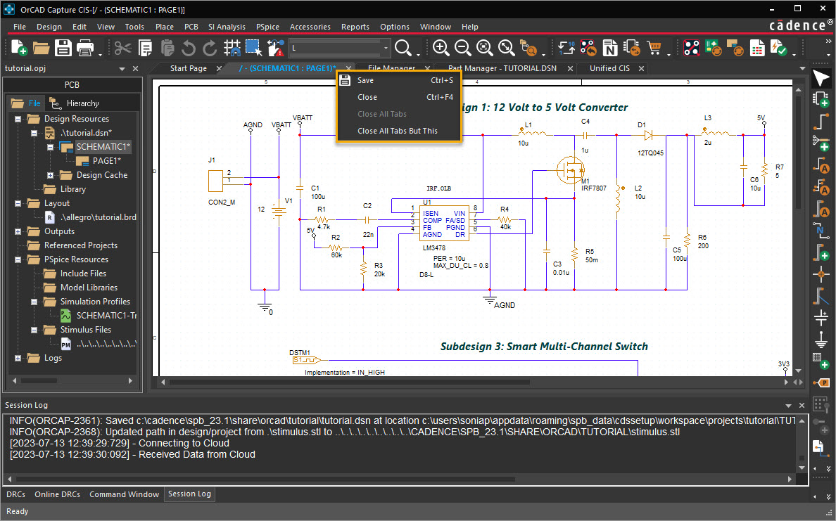
- To navigate between the open panes, click the tab for the pane or press
CTRL+TAB. - To close the current pane, right-click the tab and choose Close.
-
To close all the open panes, right-click any open tab and choose Close All Tabs. This closes all the panes open for the project.
The Close All Tabs option is not available for the project manager tab. - To close all the open panes except the currently selected one, right-click the current tab and choose Close All Tabs But This. This closes all the panes for the project except the current tab.
Capture Configuration
In this section:
- User Interface Configuration Settings
- Capture.ini File
- Customizing Menus and Toolbars
- Capture.ini Variables
User Interface Configuration Settings
Capture provides configuration settings to customize the user interface for an enhanced user experience. Various commands and dialog boxes available from the Options menu help you configure the user interface in the following ways:
- Customize the working environment specific to your system by setting preferences in the Preferences dialog box.
- Create default settings for new designs with the Design Template command. These settings are honored for the design even if it is moved to another system with different preferences.
- Override design template settings in individual designs with the Design Properties command, or individual schematic pages with the Schematic Page Properties command.
- Create default settings for new parts by setting part properties in the Part Properties dialog box.
- Override default properties on individual parts by setting package properties in the Package Properties dialog box.
Regardless of which pane in Capture, the Preferences and Design Template commands are always active in the Options menu. In addition, the Options menu contains commands specific to the currently active window. For example, when the project manager is the active window, the Options menu displays the Design Properties command. Similarly, the Options menu displays the Schematic Page Properties command when the schematic page editor is currently active.
The settings in the Preferences dialog box determine how Capture works on your system, and persist from one Capture session to the next. However, if you receive a design from another user, the preferences settings are not inherited. This implies that the colors, grid display, pan and zoom, and any other customizations you do on your system are honored even for the designs created on some other system with different settings.
The Design Template / Design Properties dialog box determines the characteristics of all the designs created on your system. Because a new design inherits characteristics from the current design template, it is a good idea to check the design template settings before you create a new design.
After you begin working on a design, you can customize its characteristics by choosing the Options – Design Properties menu command when you are in the project manager, or the Schematic Page Properties command when you are in the schematic page editor. Similarly, you use the Part Properties and the Package Properties commands on the Options menu for the part manager to set default part properties and customize the settings for individual parts.
Capture.ini File
At the startup, Capture uses a pre-defiend set of default values for the application settings. These default values are defined in the Capture configuration file—Capture.ini.
If you run Capture for the first time on a computer, it uses a pre-defined set of configurations to create the INI file. Subsequently, each time you make any configuration changes, this file is updated when you close Capture.
Location of Capture.ini
By default, the Capture.ini file is created in your HOME directory at the location %HOME%/cdssetup/OrCAD_Capture/<release>. If an INI file exists in the installation, it will be copied to the HOME location. However, you have the option of specifying any other location for the Capture.ini. To ensure that Capture uses the Capture.ini file from an different location, you need to specify the location as a command line argument to the Capture.exe.
Capture.ini Variables
The Capture.ini file contains a large set of initialization variables used by Capture. As this file is a text-based file, you have the option to modify or delete the variables and sections in this file. However, any changes you make to this file can cause unexpected behavior in Capture. So you are advised to only make changes as recommended in Capture.ini Variables.
Re-initializing Capture.ini
You can re-initialize all the configuration settings to the Capture default settings by deleting the Capture.ini file. However, these settings will only be available to you after you restart Capture.
Capture CIS Settings
The Capture.ini file also contains the Capture CIS configuration settings. These settings include the CIS parts database setup configuration settings. If you choose to re-initialize your Capture configuration by deleting the Capture.ini file, the CIS configuration settings will also be deleted.
However, Capture creates a backup of the CIS settigns in a separate file: BackupCaptureCIS.ini at the same location as the Capture.ini file. This backup is maintained each time you close Capture. So the BackupCaptureCIS.ini file contains the most recent CIS configuration settings.
If you delete the Capture.ini fie and restart Capture, you are prompted with a message to choose if you want to use the backed up CIS configuration settings. If you select yes, the CIS settings are copied from the BackupCaptureCIS.ini file to the newly created Capture.ini.
Customizing Menus and Toolbars
You can customize the menus and toolbars in OrCAD X Capture to run any TCL methods from the menus. You can also specify your own icons for the menus or toolbars items.
The resource files for menus and toolbars including the icons are located at:
<Cadence_installation>\share\orResources
To add a new menu item, you need to specify the following syntax:
<menuItem name="<menu name tag>">
<type>popup/action</type>
<label>Menu Label</label>
<enabled>true/false</enabled>
<children>
<menuItem name="<child menu tag>">
<type>action/popup</type>
<label>Child Label</label>
<enabled>true/false</enabled>
<action>TCL Action tag</action>
<update>TCL Update tag</update>
<image_16x16>image path</image_16x16>
<image_24x24>image path</image_24x24>
</menuItem>
</children>
</menuItem>
You can also add menus dynamically using TCL commands.
Capture.ini Variables
The Capture.ini file that contains default application settings is placed in the HOME directory, %HOME%\cdssetup\OrCAD_Capture\<release_version\>, in your system. However, you can specify another location for this file by using the -i switch when invoking Capture. The Capture.ini file contains a large set of initialization variables used by Capture. This section defines a set of these variables that alter the behavior of Capture at startup.
Important
- The
Capture.inifile is used by Capture at the startup. Any incorrect or corrupt information in this file can cause unexpected behavior in Capture. Before making any changes to this file, you are advised to first make a backup of your installedCapture.ini. This topic covers only a selected list ofinisections and only selected variables within these sections. It is advised that you work with only these variables. - The
Capture.inifile is a text-based file and it can be edited in any Text editor.
This topic covers initialization variables in the following sections of the Capture.ini file.
SearchToolBarSetting
This ini section includes the variables that control the selection of the Search toolbar options. You can set a Search toolbar option as selected or un-selected by setting the variable values in this section.
- Use 1 to set an option as selected.
- Use 0 (zero) to set an option as un-selected.
Search Toolbar Options
- Parts
- OffPage
- BookMark
- CommentText
- Nets
- FlatNets
- HierPorts
- DRC
- TitleBlock
- PowerSymbol
- HierPins
- PartsPins
- VariantParts
- MatchCase
- Highlight
Docking
The variables in this section enable you to set the docked window status and visibility of Capture CIS windows.
session_docked
- Set the value to
1to dock the Session Log window. - Set the value to
0(zero) to specify Session Log as an MDI window.
session_show
Set the value to 1 to ensure the Session Log window is visible at startup.
Set the value to 0 (zero) to ensure the Session Log window is hidden at startup. To display the Session Log if it is hidden, choose the Session Log option in the Capture CIS Window menu.
Print Settings
Use the variables in this section to define the print settings in Capture CIS.
InstanceMode
Set the value to 1 ensure that the default selected Print option in the Print dialog box is set to Inst. Mode (Instance Mode).
Set the value to 0 (zero) to ensure that the default selected Print option in the Print dialog box is set to Occ. Mode (Occurrence Mode).
Preferences
The Preferences section in the ini contains variables that provide access to the settings in the Capture CIS Preference dialog box.
PSpiceSymLibPath
Specify the path to libraries for PSpice simulation.
EnableITC
- Set the value to
TRUEto Enable Intertool Communication in Capture CIS. - Set the value to
FALSEto disable Intertool Communication in Capture CIS.
Footprint Viewer Type
The variables in this section describe the type of footprints that will be displayed in the CIS Explorer footprint window. The section is also linked to the the Allegro Footprints section that is then used to define the directory location for the footprint (psm) files.
type
This variable defines the type of footprints to display.
- Set the value to Allegro to use Allegro files for footprints.
- Set the value to Layout to use Layout files for footprints.
Use the dir0 variable in the Layout Footprints section to define the directory location containing the footprint files to use if the footprint type is defined as Layout. Or use the dir0 variable in the Allegro Footprints section to define the directory location containing the footprint files to use if the footprint type is defined as Allegro.
Allegro Footprints
The variable (or variables) in this section define the directory location (or locations) for the psm and pad files used by the PCB Editor 3D Footprint Viewer to display a footprint. A .psm file is used by the 3D Footprint Viewer to display the 3D footprint. A pad file is used by the Viewer to display the pin information in the viewer.
You can define any number of paths that contain the .psm and .pad files. If you define multiple paths, Capture CIS searches the directories, for the footprint files, in the order in which they are defined in this section.
If the footprint information (corresponding .psm file) is not found in any of the paths defined by the variables here, Capture CIS displays an error message in the Session Log window.
Example:
[Allegro Footprints]
Dir1=C:\Cadence\SPB_23.1\share\pcb\pcb_lib\symbols
Part Management
The variables in this section define paths to the database configuration file used in the Capture CIS flow. The configuration file identifies the ODBC data source to use, Part properties that are transferred to your design and the relationship across the tables in your preferred parts database.
If this section is missing or the configuration file paths are incorrect, you will experience errors in any CIS database operations.
Configuration File
Use this variable to define the path for the database configuration file if you are using the Licensed version of Capture CIS.
Example:
Configuration File=C:\Cadence\SPB_23.1\tools\capture\samples\BENCHACC.DBC
Frame View Options in CIS Explorer Window
The following sections let you toggle the visibility of the corresponding frames in the Capture CIS Explorer window.
- Visibility Frame
This section defines the variables of the visibility frame in CIS Explorer.
- Schematic Part Frame
This section defines the variables of the schematic part frame in CIS Explorer. - FootPrint Frame
This section defines the variables of the footprint frame in CIS Explorer. - Relational Table Frame
This section defines the variables of the relational table frame in CIS Explorer.
Each of the above sections has two variables that define the frame visibility in the Capture CIS Explorer window.
Visible
- Set the value to
1to ensure the corresponding frame is visible in the Local Part Database tab. - Set the value to
0(zero) to ensure the corresponding frame is hidden in the Local Part Database tab.
ConvertDialog
The variables in this section define the default behavior of the Save Converted Libraries and Designs dialog box. This dialog box appears when you exit Capture and you have included a configured library or a referenced design from a version of Capture prior to 16.3 in design that is based on a 16.3 or later version of Capture.
Choice
- Set this variable to
Save Allto ensure that all the displayed libraries or designs are saved to the upgraded version. - Set this variable to
No Allto ensure that none of the displayed libraries or designs are saved to the upgraded version.
Do Not Ask
Set this variable to 1 to ensure that the dialog box is not displayed each time you close Capture in the upgrade library and design mode. Capture uses the option that is set as the Choice in this section.
This option applies to referred libraries only. These are libraries that are included in a project through the Add Library command in the Place Part dialog box. In addition, when you close an older version library directly opened in Capture or when you exit Capture after opening an older version library, the application always prompts you to upgrade the library.
Set this variable to 0 to ensure that the dialog box appears each time you close Capture in the upgrade library and design mode.
OrCAD X Capture Toolbars
Toolbars are organized according to function, and the icons in these toolbars are arranged based on their menus. You can toggle individual icons on or off in the toolbar.
The OrCAD X Capture user interface includes the following toolbars that provide shortcuts to the commonly used commands.
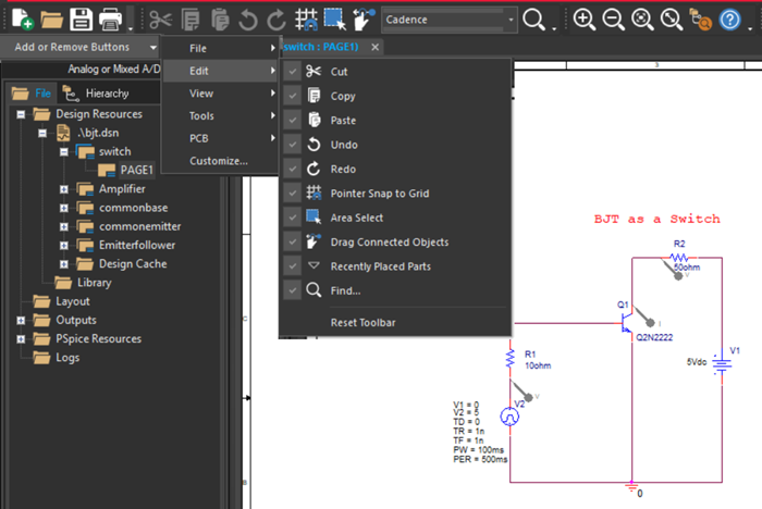
Capture Toolbar
The Capture toolbar categorizes commonly used commands under the following toolbars:
- File

- Edit

- View

-
Tools

PSpice Toolbar
The PSpice toolbar provides shortcuts to common PSpice commands. This toolbar appears only if you have a PSpice license and open a project that uses PSpice.

Draw Electrical Toolbar
The Draw toolbar provides shortcuts to commands for placing electrical components, pins, wires, and buses.

Draw Graphical Toolbar
The Draw toolbar provides shortcuts to commands for placing drawing objects, such as arcs, polylines, ellipses, and text.
![]()
Align Toolbar
The Align toolbar offers a quick and easy way to align selected objects vertically (top, middle, and bottom) or horizontally (left, center, and right) with reference to other objects. It also provides an option to equally distribute selected objects horizontally or vertically within a virtual selection bounding box. You can also align selected objects with reference to a mouse click using Mouse Mode or equally distribute the selected objects within the area defined by mouse clicks using Mouse Mode.
![]()
CIS Explorer Toolbar
The CIS Explorer toolbar offers a quick and easy way to perform common tasks. This toolbar is active only when using OrCAD X Capture CIS.

Part Manager Toolbar
The Part Manager toolbar offers a quick and easy way to perform common tasks. This toolbar is active only when using OrCAD X Capture CIS.
![]()
SI Analysis Toolbar
The SI Analysis toolbar provides shortcuts to the commands to set up a design for use with SigXplorer.
![]()
PCB Toolbar
The PCB toolbar provides shortcuts to open the following:
- Layout file
- Update Layout dialog box
- Updated Schematic dialog box
- Constraint Manager
- Design Rules Check dialog box

View the next document: 03 - Working with Projects
If you have any questions or comments about the OrCAD X platform, click on the link below.
Contact Us