03 - Inter Layer Spacing Checks
Overview
In standard PCB designs various masks and surface finishes require verification of proper clearances and coverage. Rigid Flex designs not only have the same mask and surface finish requirements, but also geometries, such as bend areas and stiffeners. These geometries, present on different layers, require verification of special clearances or overlaps of materials, and spacing between these layers.
The Inter Layer checks provide spacing checks between objects of one layer to those on another layer. These checks are usually defined for Rigid Flex designs and can also be used in standard single or multi-layer designs.
To create Inter Layer checks you need to select two subclasses, set rule type, value, DRC label and DRC layer display. You can view the effects of these rules in the Allegro X and OrCAD X PCB Editor.
You cannot create Inter layer checks between:
- Etch layers. For example, between Top etch and Bottom etch.
- Same layers. For example, between Coverlay_top and Coverlay_top.
Contents:
Inter Layer Spacing Workbook
In Spacing domain, an Inter Layer Spacing workbook provides a matrix to select subclasses, types of constraints, and their values for defining Inter Layer spacing checks. For example, you can create a check to verify spacing between conductor etch to non-etch/conductor shapes on any of the supported subclasses.
You can also import and export inter layer spacing constraints defined for different subclasses in the Inter Layer Spacing workbook.
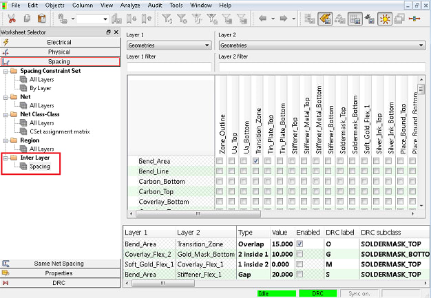
The Inter Layer Spacing worksheet has two resizable panes:
- Layer pair management pane: located at the top for adding/deleting the layer pairs.
- Constraints pane: located at the bottom for editing the constraints on the existing layer pairs.
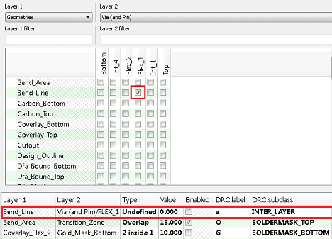
Layer Pair Management Pane
This pane consists of two columns at the top, and a matrix with check boxes for creating or deleting layer pairs at the bottom. The left column lists eligible subclasses labeled as Layer 1. The right column is labeled as Layer 2.
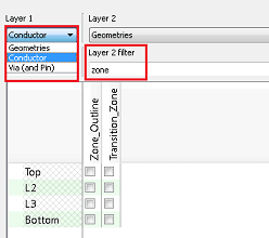
You can select from the following types of subclasses for Inter Layer checking:
| Subclass Types | Example |
| Conductor Layers | Place Bound (Top/Embedded/Bottom) |
| Pin/Via Layers | Filmmask (Top/Bottom) |
| All Mask Layers | Soldermask(Top/Bottom) |
| Rigid Flex Subclasses | Pastemask(Top/Embedded/Bottom) |
| Surface Finishes Subclasses | User-defined Subclasses |
Other classes, subclasses, and objects that are not included in the inter layer checks are:
- drawing format
- analysis
- DRC
- text (on any subclass)
- board geometry outline
- silkscreen layers
- stackup named dielectric layers
- manufacturing
- constraint regions
- all keepin and keep outs
- component value
- device type
- Ref Des
- tolerance
- user part number
Row and column filters are available with the columns to search subclasses and subclass types.
Constraints Pane
The constraint pane displays a table at the bottom of the Inter Layer Spacing worksheet.
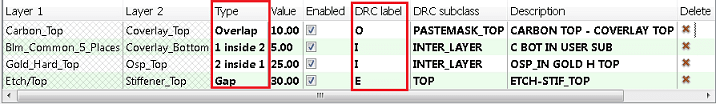
The table includes the following fields:
| Layer 1 |
A read-only field that displays the name of the subclass selected as Layer 1. |
| Layer 2 | A read-only field that displays the name of the subclass selected as Layer 2. |
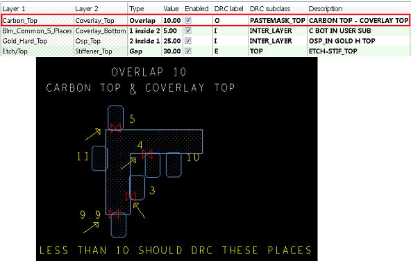
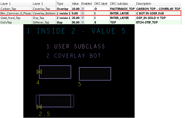
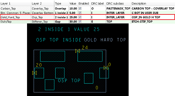
| Type |
Defines the type of spacing checks between subclasses. Four types of inter layer spacing checks are supported.
|
|
|
| Value | specifies the spacing dimension in design units. |
| Enabled | Enables spacing check for selected layer pair. You can select any of the checks to set the inter layer checks to On globally. |
| DRC Label |
Specifies a user-defined DRC marker label for the second character of the DRC. The first character "I" is reserved for Inter Layer check. The second character may be any single character from the range, a-z, A-z, or 0-9. You can also use any of the special characters. For example, I-[a-z], I-[A-Z], and so on. |
| DRC Subclass | Specifies the display subclass of the DRC marker. You can select the required subclass from the available list. |
| Description | Adds comment or description for reference. |
| Delete | Removes the selected entry from the table. |
Defining Constraints for Inter Layer Checks
To create a constraint between two subclasses, follow these steps:
- In the Spacing domain, navigate to the Inter Layer Spacing workbook.
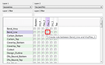
- Select the check box where the two subclasses intersects in the matrix.
Hovering over the check box highlights the row and column headers and a tooltip displays the layer pair name.
On selecting the check box, a new row is added at the top of the constraint table.
- Set the values for type, value, and DRC label.
- Select Enabled for the check.
To delete a rule:
- Deselect the check box in the selection matrix
OR - Select X in the Delete column of the constraint table for that row.
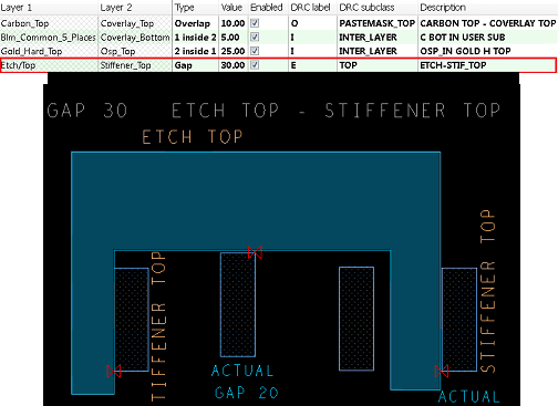
Example of Rigid-Flex Design
The following image illustrates a part of rigid-flex design in which a transition zone shape is created to verify the following design requirements:
- Vias and pins are not too close to the edge of the stackup
- Two etch subclasses on the rigid side of a stackup change to the transition zone
- Coverlay extends beyond the zone boundary
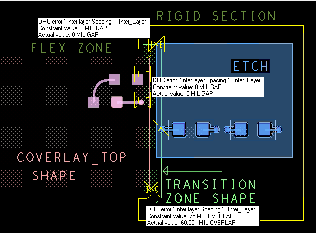
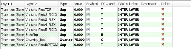
To verify these checks, the following inter layer spacing checks are defined in the constraints table:
- Gap between transition zone to via/pin
- Gap between transition zone to etch
- Overlap between transition zone to coverlay
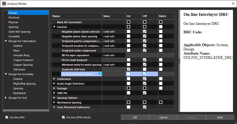
Enabling Online Inter Layer Checking
By default, the online Inter-Layer checks are set to Off in the PCB Editor.
To enable online inter-layer checking:
- Set the constraint mode for Online Inter Layer Checks in the Design Modes tab, under General in the Analysis Modes dialog box.
Exporting Inter Layer Checks
Follow these steps to export a inter layer checks:
- Choose File – Export – Technology File
OR
Choose File – Export – Constraints - Select the Manufacturing constraints check box in the Export Technology File dialog box.
On exporting a technology file (.tcfx) or a constraints file (.dcfx), inter layer checks are also included if the Manufacturing constraints option is enabled.
The exported technology file contains only inter layer spacing constraint information required for manufacturing and does not include any stackup information.
Importing Inter Layer Checks
Follow this step to import inter-layer checks:
- Choose File – Import – Technology File
OR - Choose File – Import – Constraints
Importing a technology file (.tcfx) or constraints file (.dcfx) with inter layer spacing checks in a design does not create any new subclasses. However, the inter layer checks for non-existing subclasses are imported.
The DRC subclasses not present in the destination design are mapped to the default subclass (Inter_layer) after import. You cannot enable constraints that are referenced to subclasses that are not present in the design.
View the next document: 04 - Phases in the Design Flow
If you have any questions or comments about the OrCAD X platform, click on the link below.
Contact Us