How Adding SPICE To Your EDA Workflow Makes Circuit Simulation Interactive
There’s no question that EDA (electronic design automation) tools have made PCB design easier and more accessible to the masses.
We have schematic capture tools that allow you to whip up a circuit diagram as an interactive schematic from a library of digital components, and transfer the resulting netlist to a layout editor where you can build your board. The EDA software suite keeps everything interconnected, allowing the designer to make changes to one file such as a schematic, and see it reflected in the other, such as the layout.
Wouldn’t it be great if you could apply that same level of integration and interactivity to the prototyping and testing phase of the PCB design process? It turns out you can, thanks to electronic circuit simulation with SPICE. In this post, we’ll talk about what SPICE is and how it can be used to make circuit simulation a part of your EDA workflow.
What is SPICE?
SPICE is short for Simulation Program with Integrated Circuit Emphasis, and it’s the industry standard for open-source analog electronic circuit simulation. You provide a netlist of the circuit you wish to simulate, and SPICE takes care of the rest, allowing you to generate waveform plots for analysis. SPICE gives you a way to verify the performance of your circuit without touching a single breadboard or physical component.
SPICE allows you to change component values (e.g. resistance, voltage, capacitance, etc.) and check frequency response across a range of tolerances or time periods. More advanced SPICE software even lets you run Monte Carlo analysis, perform smoke and stress tests, and create parametric plots.
How SPICE makes circuit simulation interactive
As you can see, SPICE can already be a powerful tool on its own, but where it really shines is when you integrate it into the schematic capture phase of your EDA workflow.
Electrical schematics already give you a nice big-picture view of all the electrical connections in your circuit. In fact, the components in an electrical schematic already have all the information needed to simulate an electric circuit.
Adding SPICE to your schematic capture tool essentially gives you a digital breadboard, complete with an unlimited inventory of digital components you can use to simulate your circuit. The ability to drop “probes” anywhere on your schematic and generate the corresponding waveform of the signal brings a whole new level of interactivity to your EDA workflow.
Check out how seamlessly PSpice (Cadence’s SPICE tool) integrates with OrCAD Capture:
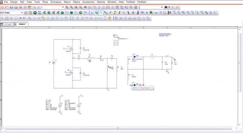
PSpice fits right into the toolbar of OrCAD Capture allowing you to place probes and plot waveforms in real-time as you design your schematic.
Ready to incorporate interactive circuit simulation into your EDA workflow? Check out Cadence’s OrCAD PSpice Designer today.