Why You Should Incorporate Real-Time Circuit Simulation Into Your EDA Workflow
It’s hard to imagine PCB design without the convenience of EDA (electronic design automation) software:
-
Schematic capture editors allow you to build circuits on-the-fly by linking component symbols together into a schematic diagram.
-
Netlists can be automatically generated into a variety of file formats with the click of a button.
-
Schematic diagrams integrate seamlessly with 3D CAD models.
-
Design rule checks (DRC) can be run to verify that physical and electrical connections are correct.
-
Generate smart PDFs, bill of materials, manufacturing files, and more.
But we’ve only scratched the surface of what EDA software can do. In this post, we’re going to cover how you can incorporate real-time circuit simulation into your EDA workflow.
Add some SPICE to your schematic capture process
SPICE (Simulation Program with Integrated Circuit Emphasis) is a type of software tool for running analog electronic circuit simulations. SPICE creates a mathematical model of your circuit by calculating complex node voltages and branch currents and frequencies across your design.
Simply input a netlist into SPICE, and you can run simulations, generate waveform plots, and identify voltage, current, and stress anomalies within your circuit design. Since the typical EDA workflow already keeps tabs on a netlist behind the scenes, integrating SPICE is simply a matter of downloading the additional tool into your existing EDA software suite. In Cadence OrCAD, that means installing PSpice and its associated libraries.
With SPICE you can:
-
Perform DC, AC, and transient sweeps of your circuit
-
Modify component values (e.g. voltage, resistance), frequency, and/or time to generate different waveform plots for analysis.
-
Identify parasitic capacitances, resistances, and other problems in your design
-
Perform statistical simulations (e.g. Monte Carlo) and predict product yield and performance over a range of tolerances.
How SPICE brings real-time circuit simulation to your EDA workflow
Do you remember the simpler times in the world of PCB design? The circuits were simple enough to take out a breadboard, pick and place components, and probe your circuit as you come up with your design. A capacitor here, a resistor there, and you bring your signal within the parameters of your expected waveform. You might start out with one design on paper that works, but find you can fine tune it for better performance by playing with the component values in your circuit.
Adding SPICE to your modern EDA workflow basically brings back the creative, free-form process of analyzing the electrical performance of your circuit as you design. It slides right into the schematic capture phase of your PCB design process, giving you a toolbar, complete with “probes” you can use to plot waveforms from different parts of your schematic.
Here’s an example of how it can work with Cadence’s PSpice and OrCAD Capture tools:
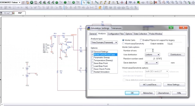
You basically get a handy toolbar within your schematic capture editor, that allows you to run real-time simulations of your circuit as you design. Provided you are using the PSpice library of components when generating your schematics, it’s possible to prototype with a wide inventory of 33,000 different parts. It would be infeasible to prototype at that scale with a physical test setup.
Conclusion
By investing a little more into your existing EDA software suite, it’s possible to gain access to powerful real-time circuit simulation software that is sure to streamline your design process. Be confident that your designs will produce an acceptable yield before you hit the manufacturing floor. Check out Cadence’s suite of PCB design and analysis tools today.