OrCAD X Enhances Bill of Materials Engineering
Key Takeaways
- After establishing core functionality, designers can use CIS Explorer and Live BOM to build BOM variants that meet different market demands or requirements.
- Data trends in Live BOM help designers and procurement stay ahead of market trends regarding cost, availability, and lifecycle status.
- Group and subgroup hierarchies in Part Manager support multiple BOM variants while keeping core circuit functionality intact.
Bill of materials engineering starts with the schematic but evolves alongside the design.
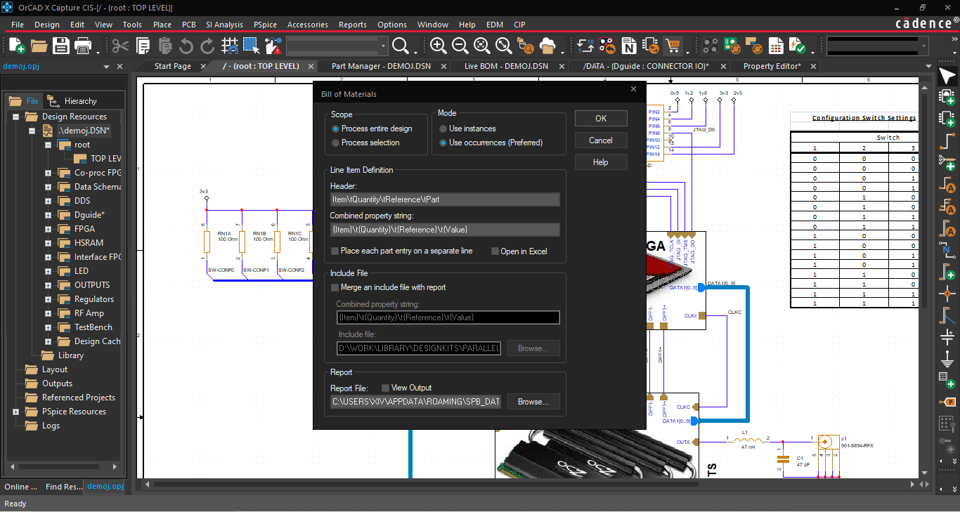
Managing the bill of materials can be an overwhelming task. Between determining the basic functionality of the circuit and sourcing cost-competitive components during continued supply chain issues, it’s easy to introduce cost overruns that can jeopardize a project’s profitability. Bill of materials (BOM) engineering optimizes all aspects of the assembly process using an in-circuit performance and organizational efficiency approach. OrCAD X Capture allows users to rapidly simulate, select, and purchase components for a quicker turnaround for procurement and manufacturing in general.
How OrCAD X Fosters BOM Creation
|
Core Design |
Variants |
Sourcing / Procurement |
|
|
|
Bill of Materials Engineering With Component Sourcing Support
Managing a BOM is among the first items in the design process that pushes the design toward a realizable, manufacturable product. At the same time, it also shapes the schematic. While the physical dimensions of the components are unimportant at this abstraction level, different pinouts will form the logical connections of the board-defining netlist.
There are two general tasks to keep track of while designing the BOM:
- Establishing the circuit's functionality - While optimizing placement, routing, etc., during the layout process will impact in-circuit performance and reliability, the BOM components provide the defining features. Engineers and designers must work from prior revisions, manufacturers’ suggested layouts, simulations, etc., to determine potential components that meet the requisite circuit performance characteristics.
- Selecting the most appropriate components - Since components can have thousands of similar sizes, packages, ratings, and tolerances that affect cost and reliability, engineers will want to settle on the manufacturer’s part numbers (MPNs) that most efficiently meet the board's mechanical and electrical requirements. Some of this work can fall to a procurement/sourcing team that uses the engineering team’s guidelines to select the most appropriate components, especially when dealing with bulk purchases.
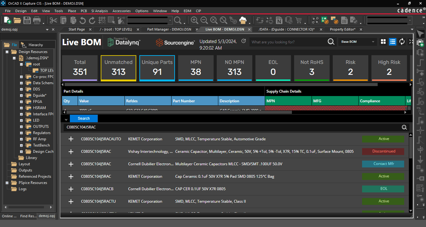
Live BOM gives design and procurement teams a quick and easy method for sourcing components within a unified ECAD platform.
However, only some teams may have access to procurement specialist resources before engaging with the manufacturer, and the general left-shift towards design from manufacturing to save time and limit cost overrun means design teams may do better to take matters into their own hands. With Live BOM in OrCAD X, designers can select from a part catalog with billions of unique components and up-to-the-minute updates on cost, availability, and more. Designers can also see additional supporting information, such as production status and RoHS compliance.
Handling Core Design Variance With BOM Variants
During product development, features and scope of the circuit may change due to end-user demands or the general nebulousness of designs as they approach first-pass manufacturing. Design variants relating to “do not install” (DNI) components may necessitate separate BOMs to encompass the component changes and keep track of alternate options. Managing a single BOM is challenging, but ensuring consistency between multiple BOM variants while adding or removing circuit blocks can quickly result in procurement or manufacturing issues.
With OrCAD X Capture, it’s easy for users to build variant BOMs from the core design. Users can define groups and subgroups within the Part Manager to categorize BOM variants for supply chain resilience, differences in regional material requirements, and other manufacturing considerations:
- Groups represent discrete circuit functionality, such as power and memory. Whenever designers need to add or swap circuit functionality, the group handles all changes to the BOM.
- Subgroups are group variants that reflect the same or similar functionality with different components, like changes in passive component values, tolerance, package type, and other attributes.
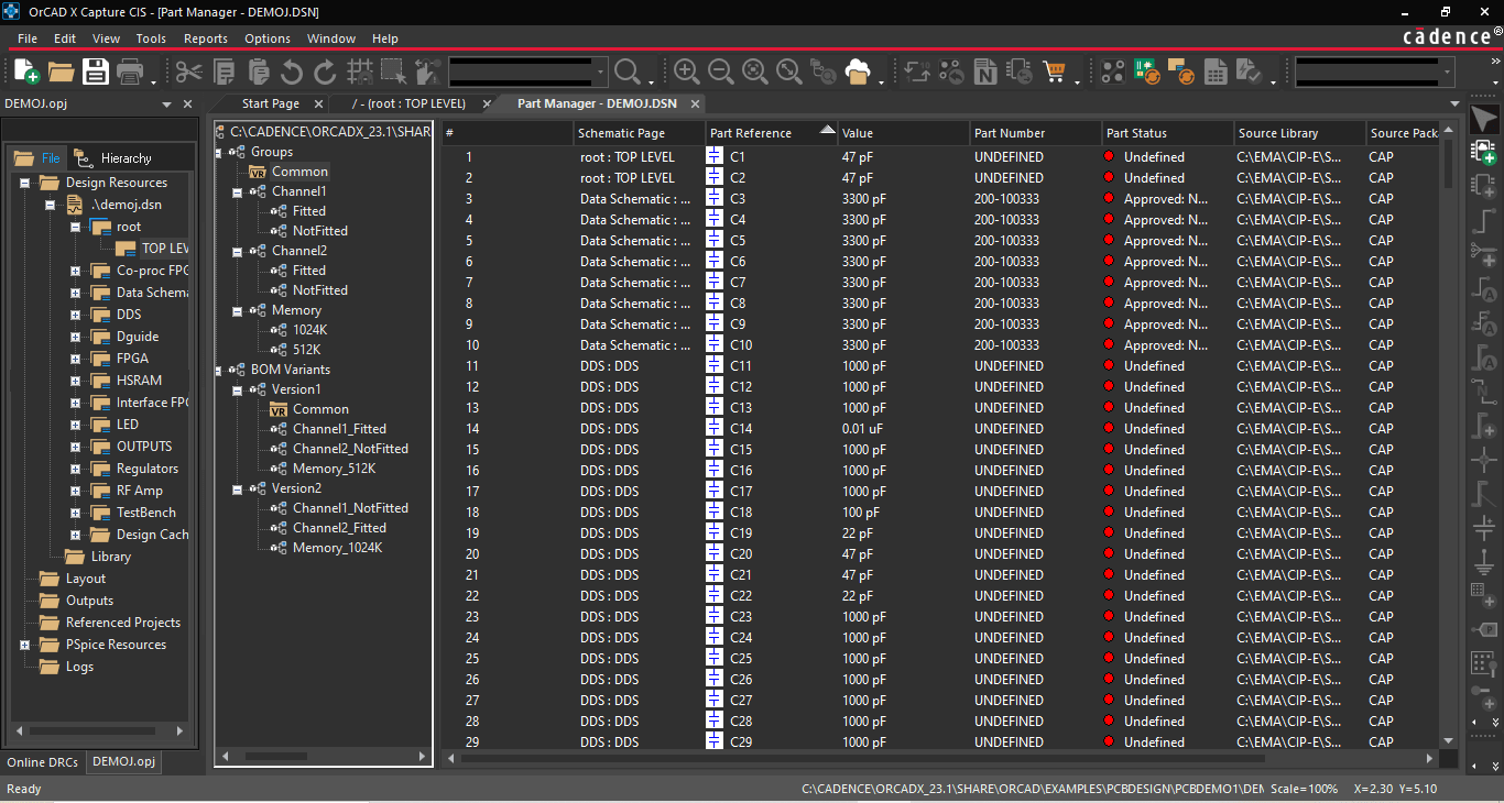
Designers can use BOM variants to modify circuit blocks of the core design using Groups and Subgroups.
The Common folder at the top of the Part Manager tree stores all the unassigned components associated with the design, i.e., all variants of the core design inherit the components within the Common folder. Moving components to groups and subgroups removes them from the Common folder and allows for association with a BOM variant. This structure makes it easy to manage the BOM contents of the core design and variants simultaneously, as designers only exert minimal work defining the differences between variants, expediting design turnarounds. When selecting the Link Database Part command for the CIS Explorer, the core design and BOM variants will update contextually:
- Linking components from the root folder will update the core design and all groups and subgroups inheriting from Common.
- Linking components from a group or subgroup folder will only update the component for all particular group or subgroup occurrences. A warning message will be displayed to prevent netlisting and downstream assembly issues if there is a mismatch between the footprint of the core design and the updated component in the group or subgroup.
Accelerate Design Turnaround And Improve BOM Suitability
Bill of materials engineering can be challenging due to balancing a design’s many iterations as it coalesces into a final product. Fortunately, the new OrCAD X platform aids design teams by pairing its renowned CIS Explorer with Live BOM to make comprehensive component sourcing faster than ever. Looking to optimize your PCB design even further? See how Cadence’s PCB Design and Analysis Software gives design teams the tools to meet the challenges of modern electronics.
Leading electronics providers rely on Cadence products to optimize power, space, and energy needs for a wide variety of market applications. To learn more about our innovative solutions, talk to our team of experts or subscribe to our YouTube channel.