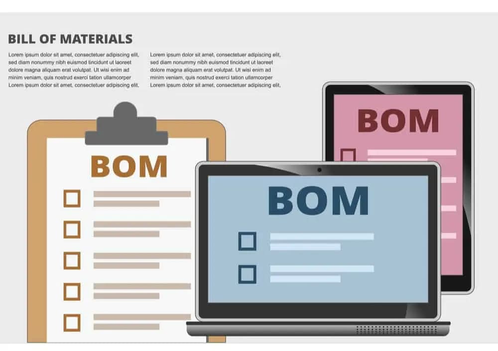
BOM in PCB Design: Key Data and Workflow Integration
Key Takeaways
-
An electronic BOM is the centralized source that lists out the raw materials, components, assemblies, and other related items that are needed to build a PCB.
-
An electronic BOM opens a communication channel between the different departments regarding the components used in a design.
-
Access to tools like OrCAD X Live BOM keeps BOMs current through real-time updates during design iterations.
An electronic BOM in PCB design is usually a systems-generated list using computer-aided design (CAD) software or similar software systems
A bill of materials, or BOM, in PCB design is critical for manufacturing a PCB. The engineering BOM is the source that provides comprehensive information regarding the raw materials or items required to make a finished product. While constructing a printed circuit board or electronic product, engineers prepare electronic BOMs. Let’s explore the electronic BOM in PCB design, its importance, and how to make a BOM.
In the fast-paced world of PCB design, having comprehensive PCB BOM data at your fingertips is key for smooth production and supply-chain management. Below is a detailed breakdown of key PCB BOM data types to incorporate for streamlined component procurement and PCB manufacturing.
BOM Data PCB: Datatypes and Details
The electronic BOM data PCB is generated usually as a spreadsheet or something resembling a spreadsheet. Columns in the electronic BOM specify the fields or captions that give you complete and accurate information regarding a part or components, and each row corresponds to a part present in the design. The following are some of the column captions that describe BOM Data for PCB design.
|
Data Type |
Details |
|
Part Number & Name |
- Unique identifier and human-readable name - Source: Manufacturer catalogs, PLM systems - Use: Precise ordering & inventory tracking |
|
Quantity |
- Units required per assembly - Source: CAD/BOM export, engineering specs - Use: Material planning & costing |
|
Manufacturer & Supplier |
- Part maker and seller - Source: Approved vendor list, procurement database - Use: Sourcing decisions & performance tracking |
|
Unit Cost & Currency |
- Price per part in the given currency - Source: ERP/pricing systems, supplier quotes - Use: Cost roll-up & budgeting |
|
Lead Time & Availability |
- Procurement lead time and stock status - Source: Supplier portals, MRP/ERP system - Use: Scheduling & risk mitigation |
|
Material Specifications |
- Physical/chemical properties - Source: Datasheets, material libraries - Use: Compliance checks & performance validation |
|
Compliance & Certifications |
- Regulatory/environmental approvals (RoHS, REACH, ISO, UL…) - Source: Certification databases, filings - Use: Regulatory reporting & market access |
|
Lifecycle Status |
- Phase in lifecycle (active, obsolete, phased-out) - Source: PLM, vendor notifications - Use: End-of-life planning & serviceability |
|
Revision & Change History |
- Design revisions and ECO records - Source: ECM/ECO systems - Use: Traceability, quality control & audits |
|
3D CAD Links & Drawings |
- Links to CAD models and drawings - Source: PDM/PLM vaults - Use: Assembly guidance & visualization |
|
Environmental Impact |
- Recyclability, carbon footprint, conflict minerals - Source: Sustainability databases, disclosures - Use: ESG reporting & sustainability assessments |
|
Custom Attributes |
- User-defined fields (dept., project code, handling notes) - Source: Internal databases, user input - Use: Project-specific filtering & reporting |
The Electronic BOM in PCB Design
Printed circuit board design has many complexities and challenges associated with each stage of PCB design. Even the sourcing of components for a circuit board can bring complications or disagreements between internal teams. Documenting the details of the circuit board components or raw materials can be helpful in such cases, which is why electrical BOMs are created by designers. Electronic BOMs can alleviate the complications involving raw materials, components, and assemblies.
Who Uses Electronic BOMs?
A BOM in PCB design is vital for manufacturers, customers, and assemblers. For students and young engineers just learning PCB workflows, understanding how to create a BOM is a critical first step in ensuring accuracy and efficiency downstream. The electronic BOM opens a communication channel between different departments regarding the components used in a design.
When you first draft your schematic in CAD software, generating a BOM introduces you to best practices in part selection, cost estimation, and compliance checking. Imagine you are designing your hardware project and are sharing the PCB fabrication and assembly with your chosen manufacturer. As a customer, you can use the electronic BOM generated from the CAD software to effectively explain to the PCB fabrication and assembly service what exact service you are looking for.
Every stage of PCB development relies on the electronic BOM in some way.
-
During procurement the sourcing of the components is performed according to the electronic BOM.
-
The PCB fabrication and assembly services refer to the electronic BOM as the base for preparing the quotation of their work as well.
-
The PCB assembly service utilizes the BOM to build the board as per the customer specification.
-
PCB fabrication machines are also configured and programmed based on the electronic BOM.
-
Finally, the PCB manufacturer relies on the electronic BOM to fabricate and assemble the board.
Common Details Included in an Electronic BOM
The electronic BOM is generated as a spreadsheet. The columns in the electronic BOM specify the fields or captions that give you complete and accurate information regarding a part or components, and each row corresponds to a part present in the design. The following are some of the column headers that describe a somewhat decent electronic BOM.
-
Item: The first columnn of an electronic BOM is usually the item that is used as an index for all the specifications on the list.
-
Reference or designator: The reference or designator refers to the alphanumeric name of the component as per the PCB schematic design. It aids in the positioning of the component on the board.
-
Quantity: The quantity is the number of units of each component required in the board design.
-
Value: The value of the particular component can be given in the electronic BOM. However, this is optional when the electronic BOM provides the part number.
-
Part number: The part number, otherwise called the manufacturer part number (MPN), is the unique number given by the manufacturer to identify each part.
-
Manufacturer: When the manufacturer’s name is provided in the electronic BOM, it is easy to navigate to the manufacturer's catalog or website and identify the part.
-
Description: The part is described under this caption by providing details such as color, size, weight, and electronic parameters like voltage, current, power, etc.
-
Package reference: The packaging reference specifies the package used by the part, such as QFN16 or 20-SSOP, or it gives the footprint information of the part such as 0603, 0805, etc.
More fields can be included in the electronic BOM such as the mounting type or alternative part number. You can use different electronic BOM formats by compiling them by hand or automatically generating them using PCB design software.
Where BOM Creation Occurs in PCB Design Workflow
In a typical PCB design workflow, the BOM is first generated once your schematic is complete and all components are placed. From that point forward, it must become a living document: as you iterate on your schematic or layout, add or swap parts, or adjust quantities, your BOM needs to stay in sync.
In general, BOM integration with your CAD tool can help make sure that lifecycle statuses (active, obsolete, or phased-out) and compliance data are automatically flagged. By ensuring your BOM is updated in every stage—from initial part selection and footprint assignment, through ECO-driven revisions and procurement handoff—you can maintain traceability, streamline component sourcing, and reduce the risk of last-minute surprises. However, constantly referring back to the BOM with each change in the PCB to update it can become cumbersome and can introduce errors.
BOM Creation in OrCAD X
OrCAD X Live BOM takes integration a step further by generating and updating your bill of materials continuously as you work on the schematic and PCB layout. Instead of manually exporting and reconciling spreadsheets, Live BOM runs in the background, capturing every component change, substitution, or annotation in real time. That means you always have an accurate, up-to-date BOM without repetitive exports—and you can take advantage of its advanced risk scoring, market insights, and alternative-part suggestions without ever leaving your design environment.
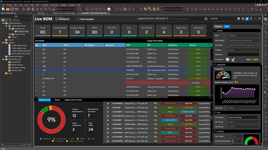
OrCAD X Live BOM automatically updates component values
To generate a BOM with OrCAD X Live BOM, start by enabling the Live BOM panel in your schematic editor by going to the Tools->Live BOM menu in OrCAD X Capture—no additional exports are needed. As you place components, Live BOM automatically captures each part’s reference designator, value, MPN, manufacturer, package, and custom attributes. You can customize column visibility and supplier-data feeds in the Live BOM settings, choosing which cost, lead-time, compliance, and risk metrics to display. Once your design is complete (or at any iteration), simply click “Refresh BOM” to pull in real-time supplier information and generate the latest part-list. You can then preview, filter, or sort directly in the panel, or export to CSV, Excel, or your PLM system—keeping your BOM accurate and aligned with your schematic without manual reconciliation.
A well-managed BOM in PCB design is central to effective part sourcing, compliance tracking, and cost control. OrCAD X simplifies BOM creation by integrating live component data directly into your design workflow. To explore how OrCAD X supports real-time BOM accuracy and efficient PCB development, visit the OrCAD X platform or start with a free trial of OrCAD X.
Leading electronics providers rely on Cadence products to optimize power, space, and energy needs for a wide variety of market applications. To learn more about our innovative solutions, subscribe to our newsletter or our YouTube channel.