How to Create a BOM File With OrCAD X
Key Takeaways
-
Users can generate multiple BOM types/reports from the top navbar in OrCAD X.
-
Design variants – similar designs with regional component variations, circuit block differences, etc. – have BOM tool support.
-
Users looking to optimize or check the supply chain resilience of their BOMs can use Live BOM to check production status, availability, and replacements for component MPNs.
OrCAD X users needing clarity on how to create a BOM file should look no further than the top navbar.
The bill of materials (BOM), alongside the schematic, is one of the driving design documents for PCB layout, providing manufacturers’ part numbers (MPNs) for datasheet review, footprint creation, and assembly procurement. It may be tempting to ask “how to create a BOM file” when faced with a new design; the process may be more complex than a simple toolbar selection as the BOM (like the schematic) evolves with the project, and designers will need to account for the changes both in functionality/performance and market metrics that can complicate the realities of PCBA manufacturing. OrCAD X gives design teams a wealth of tools for analysis and organization that make BOM management a breeze, all within a unified software platform.
BOM Types in OrCAD X
|
Location |
Part References grouped by MPN? |
|
|
Standard BOM |
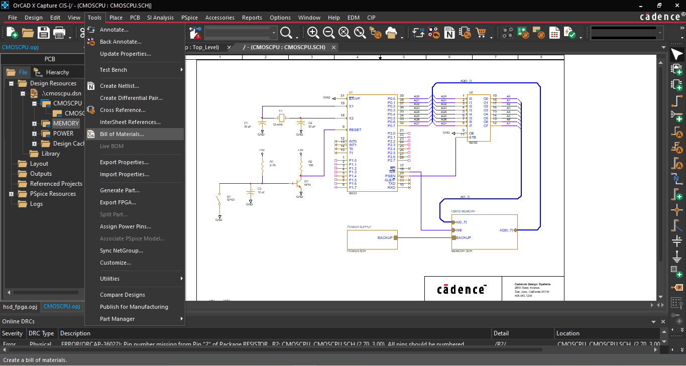
In the top navbar, navigate to the “Tools” dropdown, then select “Bill of Materials.” |
Yes. |
|
CIS BOM |
In the top navbar, navigate to the “Reports” dropdown and select “CIS Bill of Materials.” |
No. |
Learn The Simple Steps of How to Create a BOM File
Creating a BOM file from the OrCAD X Capture menu is quick and straightforward: navigate to Tools > Bill of Materials from the top navbar in an open project to open the Bill of Materials dialog box. With a few clicks, users can easily output a .bom file within the project hierarchy that displays a few standard categories like line item, quantity, reference designator, and description (users can add additional parameters in the Bill of Materials dialog). This format is the most concise BOM and prevents an unwieldy length to the list by grouping identical components within a single line; since these components have identical parameters and footprints, there’s no need to expand the list unnecessarily such that each reference designator receives an individual line readout. However, this method does not produce an exportable BOM file; instead, designers can think of it as a quick method to generate an at-a-glance overview of the BOM in its current iteration.
Users can select CIS Bill of Materials under Reports in the top navbar for a BOM that is more suitable for manually assigning footprints. Here, each reference designator receives an individual line readout that is more akin to the view within the Part Manager. The primary advantage here is that users can export this list to an Excel spreadsheet for editing, and like with the “collapsed” BOM that groups identical components’ reference designators within the same line, users import different part properties into the BOM file and change their ordering of the columns. However, users also have the option to keep this BOM format natively viewable within OrCAD X by keeping the “Export BOM to Excel” box unchecked. It’s also possible to select between different BOM Variants organized within Part Manager for output, making it easy to switch between multiple BOM outputs within a single project.
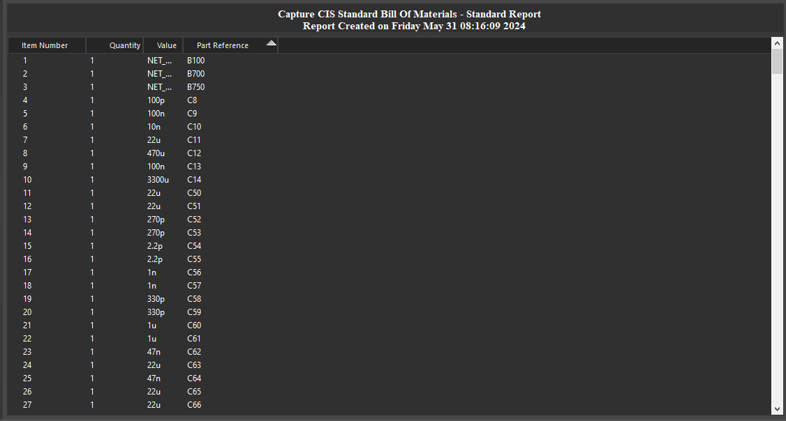
The CIS Bill of Materials separates lines by Part Reference designator.
Iterating and Analyzing the BOM
What are BOM Variants? During the initial stages of project planning, the design details are not necessarily concrete and may shift according to market forces and changes in the project scope. To address this, users can build out Groups and Subgroups within the Part Manager that explicitly indicate the differences between circuit block variants (for example, through-hole vs. SMT when availability/lead times favor the former, lower tolerance vs. higher tolerance components when performance of the former are acceptable, etc.) Using BOM variants minimizes the work necessary to iterate changes from the core design by keeping all of the shared elements of the BOMs in common. In addition to saving time, eliminating the repeated work of filling out the BOM prevents mistakes and mismatches between variants.
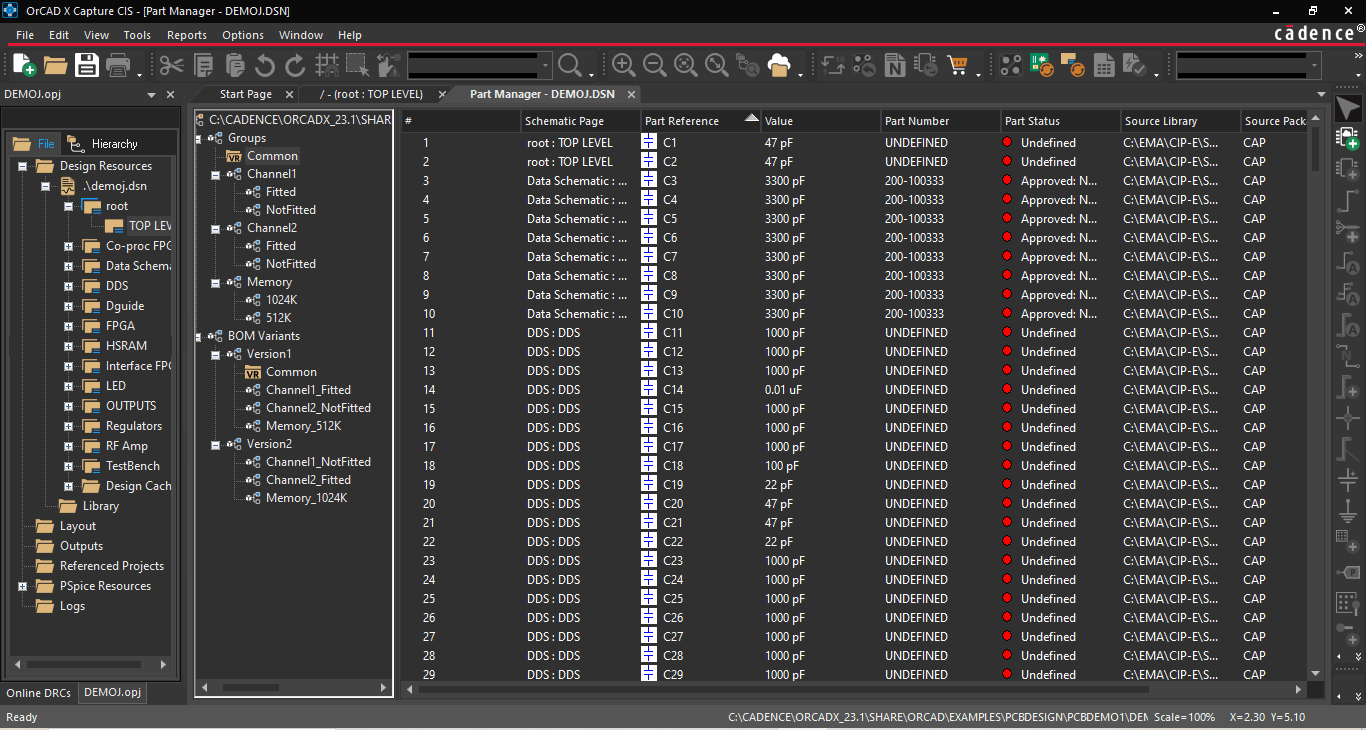
BOM variants allow design teams to juggle multiple similar designs deftly.
Selecting components for the BOM will depend on functionality, but market factors such as cost, availability, and lead times can interfere with project budgets and deadlines. Before finalizing component selection, OrCAD X Capture users can check the status of their BOM with the new Live BOM dashboard. The top of the dashboard will show a general risk profile of the BOM based on component availability and the multitude of replacements (equivalents, alternatives, and drop-ins). Filter selections at the top of the dashboard help users quickly hone in on areas of the BOM that are noncompliant with manufacturing standards or lack the requisite information for analysis. Analysis of individual components shows easily digestible graphs and data for market analysis to optimize procurement.
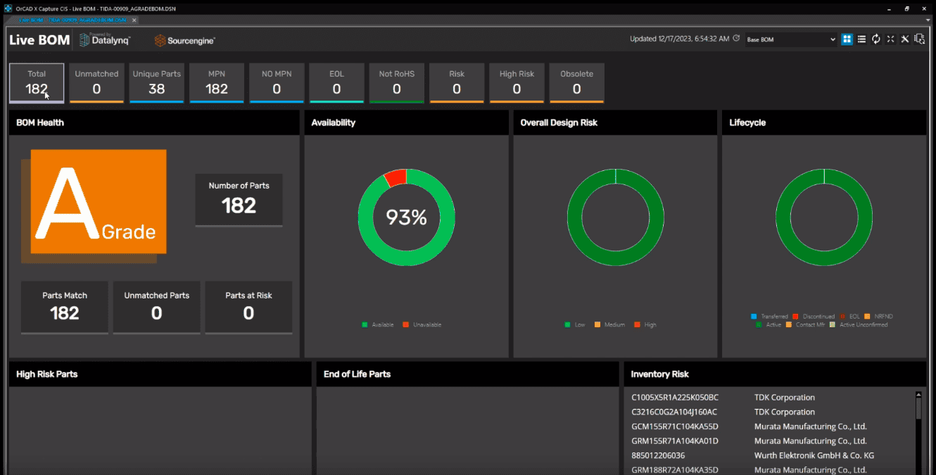
Live BOM gives users an at-a-glance risk profile of their BOM components.
Cadence BOM Tools Seamlessly Segue Into Manufacturing
While the answer to “how to create a BOM file” is straightforward, the work that goes into designing and maintaining a BOM (or multiple, in the case of design variants) requires constant market analysis. Fortunately, with OrCAD X, it’s easy to ensure that designs are optimal and that any changes between design variants receive proper accounting. Additional BOM footprint management from leading data vendors allows design teams to accelerate design timelines for tight time-to-market deadlines. Looking for additional design tools? See the full suite of Cadence PCB Design and Analysis Software.
Leading electronics providers rely on Cadence products to optimize power, space, and energy needs for a wide variety of market applications. To learn more about our innovative solutions, talk to our team of experts or subscribe to our YouTube channel.