OrCAD X Error Codes
Key Takeaways
-
OrCAD X error codes can arise during normal use and offer tips for insight.
-
When in doubt, the best solution is to review the error code online through the community forums or by submitting a support ticket.
-
Careful usage of the DRC can identify potential manufacturing errors during schematic design and board layout.
Schematic design and board layout can be intimidating and complex for the inexperienced. Navigating error codes with shorthand summaries that are difficult to diagnose can become even more challenging. While PCB software like OrCAD X offers users extensive functionality and rich features, learning how and where different error messages pop up can help users prevent their occurrence in the first place. Users can submit a support ticket for their OrCAD X error codes in the Cadence portal or community forums for a more thorough analysis.
OrCAD X Error Codes, Warnings, and Violations
|
Error Codes |
Warnings |
Violations |
|
|
|
Resolving OrCAD X Error Codes
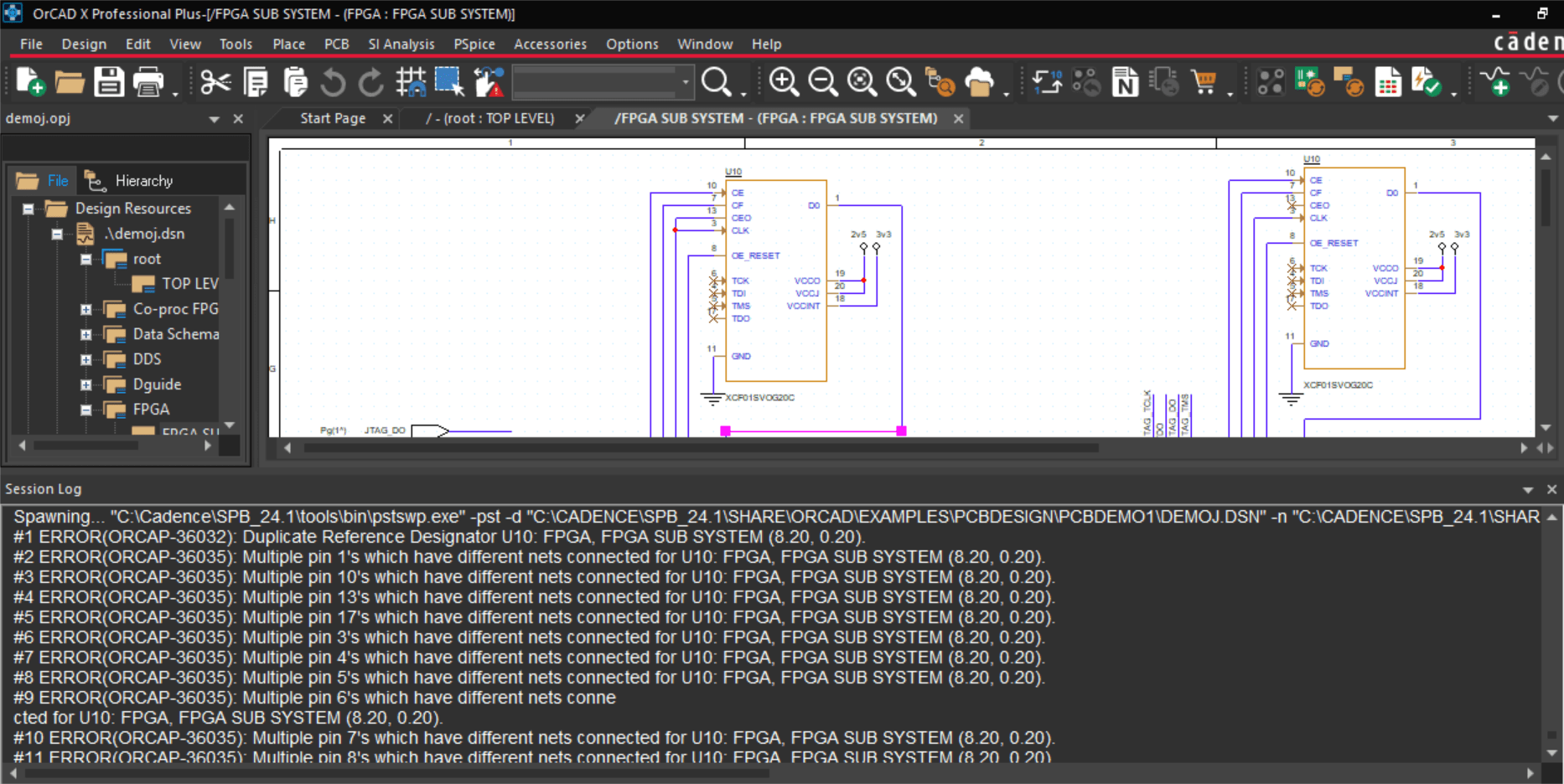
A prevalent error users should be aware of is trying to import a newer design into an older version (e.g., a 24.1 schematic file into a version 17.2 software installation). Files are backward compatible with older versions to an extent; however, they are always forward compatible, which means you can update an older version of a file within a newer version of software installation. To uprev a design, you can use DBDoctor or File - Save depending on how many versions you’re moving forward. To downrev a design (via PCB Editor) you can go to Export - More - Downrev Design. Also, be wary of files imported and translated from other ECAD software – imperfections in the translation process can result in logic that deviates from the original document. Review the original and translated versions and run a schematic design rule check (DRC) for a more detailed analysis.
Consider some of the areas where error codes may arise during the design process:
-
Schematic design - Many schematic issues related to component parameters and, ultimately, netlisting (importing the design to the board) arise from incorrectly attributed schematic symbols, footprints, and sometimes duplicate reference designators. Check the schematic for full continuity (ensure wires snap to pins and are not left floating). Deleting and replacing the offending symbols can often regenerate the conflicting components without error in the case of duplicate reference designators. Some additional items worth mentioning:
-
Pin name/number - The default orientation for pin names is the blue text inside the package body, whereas the default orientation for pin numbers is the black text outside the package body above the pin. Ensure correct pin numbering relative to the package's pinout.
-
Netlisting - To address any issues when netlisting, view the session log (typically docked to the bottom panel). The session log lists each warning and error message, allowing users to address them sequentially. Note that warnings will not interrupt tasks but can lead to issues if unaddressed; it’s up to the user to determine whether the warning requires a resolution.
-
Board design - Errors at the board level are more often caused by manufacturing errors than logical errors, although the latter still apply. Among the more obvious issues like shorted and unconnected nets, there are more subtle oversights like unassigned shapes, missing teardrops, and dangling vias and traces (which can form antennae).
Resolving Common OrCAD X Error Codes
OrCIS-6245 and OrCIS-6250
There are a few reasons users may encounter these errors. Begin by troubleshooting these issues:
-
Corrupt .ini file - Close OrCAD X Capture, and locate the capture.ini folder in the OrCAD X Capture installation directory. Rename the folder to capture.ini_backup and relaunch OrCAD X Capture. If this does not solve the issue, rename the capture.ini file.
-
Spaces in tables or property names - First, open the capture.ini file and modify it with the following command:
[Part Management]
Field Qualifier = “
Table Qualifier = “
Then setup and configure the Open Database Connectivity (ODBC).
-
CIS Property Field >255 characters - By default, the width of any prosperity is one byte. To increase this width, go to the command window and run the following Tcl command
setCISFieldLength 8000
This command updates the capture.ini file and only needs to be set once.
-
A 32-bit operating system - OrCAD X requires a 64-bit operating system.
-
Database is “read-only” - Check the database file’s properties and ensure it’s not set to read-only. If using the ODBC setup, also check that the “Read-Only” driver is unselected.
-
Errors occur when using the Query tab in CIS Explorer - OrCAD X Capture reads data from the capture.ini file instead of the Database Connectivity (DBC) file until the user performs an operation within CIS. Doing so should cause the program to read from the DBC file and display the correct information.
-
ODBC drivers are out-of-date - Install the newest drivers and reconfigure the database.
-
Database field names contain special characters - Remove any special characters (like apostrophes) from database field names.
Preventing Manufacturing Issues With the DRC Browser
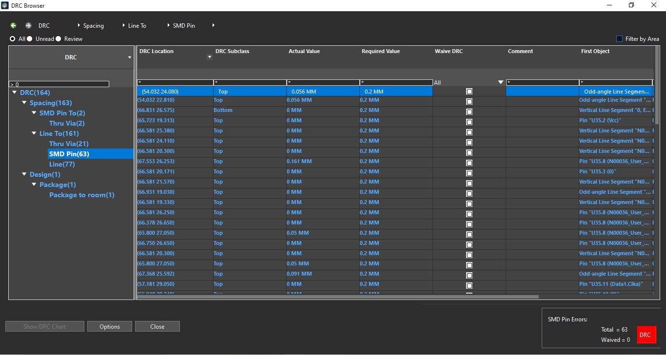
Launched from the Constraint Manager, the DRC Browser has an easily navigable list of all design rule violations in the design and synchronizes to the layout, giving designers an easy way to track and correct violations. The left column of the DRC Browser has a collapsible list where users can expand DRC flags by type of violation. The right column contains a breakdown of the violation, including location, conflicting object(s), and constraint source. By right-clicking an entry in the right column, users can jump to the flag in the layout, mark it for review, or waive the violation.
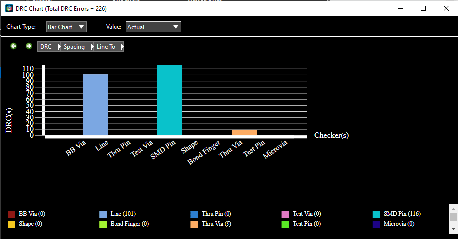
The DRC Browser can also output the list of DRC violations as a more readable bar or pie graph. Users can further specify a breakdown by DRC violation type.
Cadence Solutions for Error-Free Manufacturing
OrCAD X error codes give designers insight into how to correct their design or tool settings. When preparing a design for simulation or production, designers must be able to quickly resolve file management issues during design. The OrCAD X platform makes it easy for designers to streamline workflows and catch potential issues during schematic design and board layout. Interested in learning more or exploring the platform? Try OrCAD X for free today.
Leading electronics providers rely on Cadence products to optimize power, space, and energy needs for a wide variety of market applications. To learn more about our innovative solutions, subscribe to our newsletter or our YouTube channel.