04 - Managing Parts
Overview Parts and Libraries Creating Hierarchical Blocks Creating Parts Editing Parts Part Properties Design Cache Part Packages Part Instances and Occurrences Removing Part Reference Assignments Generating Library Parts Managing Split Parts Deleting a Part Creating Components Sharing Components Managing Categories Managing Mechanical Assemblies Configuring CIS OnCloud Database
Overview
Parts usually correspond to physical objects—gates, chips, connectors, and so on—that come in packages. Think of these packages as physical parts and the parts you place on a schematic page as logical parts. Physical parts that comprise more than one logical part are sometimes referred to as multiple-part packages. To keep it simple, both are referred to as parts in Capture.
A package consists of one or more parts. Depending on the type of parts in a package, a package is classified as a Heterogeneous or Homogeneous part.
Homogeneous Parts
Logical parts in a package may have different pin assignments, graphics, and user properties. If all the logical parts in a package are identical except for the pin names and numbers, the package is homogeneous. For example, a hex inverter is homogeneous—the six inverters are identical, except for their pin numbers.
Heterogeneous Parts
If the logical parts in a package have different graphics, numbers of pins, or properties, the package is heterogeneous. For example, A relay—that has a normally opened switch, a normally closed switch, and a coil—is heterogeneous. The three physical parts differ in graphics, number of pins, and properties.
Split Parts
A split part is a multi-sectioned package. You may need to section a part for different reasons:
- Your design may include parts that have thousands of pins. Such large-sized parts may not fit in a single schematic page. To handle such parts, you can split them into multiple sections based on your specification and can place different sections in different schematic pages. This will ease designing.
- You want to partition a large part based on its functionality and use sections individually. For example, you may like to create different sections for pins with the same voltage rating.
Parts and Libraries
Capture ships with more than 400 part libraries. To place a part on your schematic, you will first need to search for the part, and then place the part on the schematic page.
Searching for Parts
You can search for a part in the Place Part window. In this window, you can select one or more libraries to search. This method is useful if you know the library (or group of libraries) in which the part exists. Alternatively, you can search for a part from the libraries contained in a Windows directory.
To search for a part in the selected libraries, do the following:
-
Choose the Place – Part menu command.
In the Place Part window, add the libraries in which you want to search for the part. - To add a library, click Add Library.
- In the Browse File dialog, select
<the library to add>.
To add multiple libraries:
- Use the
Ctrl +click or theShift +click combinations. - Choose one library at a time. Use this method if the libraries to add are in different directories.
- Use the
- In the Libraries list, choose the library (or libraries) within which you would search for the part.
To select multiple libraries, use theCtrl +click or theShift +click combinations. - To use the Filter command, click the Filter button.
- In the Part text box, enter
<the name of the Part>.
You can use the * (asterisk) or ? (question mark) wildcard characters to search.
Notice that as you type, Capture auto-completes the Part name. - Press
Enter.
To search for a part in all the libraries in a directory, do the following:
- From the Place menu, choose Part.
In the Place Part window, add the libraries in which you want to search for the part. - Click the Plus sign to the left of Search for Part at the bottom of the Place Part window.
- In the Search For text box, enter the name of the part to search.
You can use the * (asterisk) or ? (question mark) wildcard characters to search. - Click the Search button.
Capture scans the libraries in the selected directory, and lists all the parts that match the name or wildcard. - In the Libraries list, select the library containing the part you want, and click Add.
If you need to know a part's library of origin, you can select the part in the project manager, then select Replace Cache from the Edit menu. The part name and the library and path are listed in the dialog box that appears. - Click Cancel to return to the project manager.
Placing a Part
Parts are stored in libraries. In addition, you can create your own parts in custom libraries. Some library parts have a convert as well as the normal graphical representation. Many packages contain more than one part, in which case you may need to specify which of the parts to place.
To place a part, do the following:
- Choose the Place – Part menu command.
The Place Part window is displayed. -
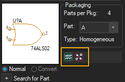
From the Parts list, select the part you wish to place.
When you select a part, the PSpice symbol is displayed for a part that can be simulated using PSpice and the layout symbol is displayed for a part that is supported for PCB Editor flow. The symbols are displayed below the Packaging box.
When you place a part, ensure the following:
- To place a convert version of the part, select Convert in the Graphic group box.
- If the package contains more than one part, select one of the parts from the drop-down list in the Packaging group box.
The part appears in the preview box. -
In case of a heterogeneous part, you need to decide which part in the package you want at this time, because you will not be able to change the part in the package after the part is placed. Whether the part is homogeneous or heterogeneous, if you are placing multiple copies of the same part in the package, you do not need to specify the part number at the time of placing the part. Capture automatically increments the part numbers as you place the parts on the schematic.
- Click the Place part button.
OR
Press Enter.
An image of the part is attached to the pointer.
Press F6 to change the cursor to a crosshairs to place the part at a specific location. - Move the part image and click to place the part.
- Press the ESC key or select another tool to dismiss the part that is attached to the pointer.
The first time a part is placed, a copy of the part is created in the design cache.
If a part is placed off the grid, it remains off-grid throughout any cut-and-paste and drag-and-drop operations.
Recommendations when Placing Parts
If you place parts so that two pins meet end to end, the pins are connected. However, it is recommended to connect the pins of the parts using a wire instead of placing them end to end. This is because, parts with direct pin-to-pin connections produce a system-generated net name to establish the connection which may pose the following limitations:
- You cannot assign your own net name in the place of the system-generated net name.
- Searching for the system-generated net name can be difficult if you are not aware of the pin to pin connection.
- If you move the parts after creating the netlist, the system-generated net name might change. This may cause net name conflicts when you run back-annotation.
It is recommended to not connect a power symbol directly to a power pin. Connect the power symbol to the power pin using a wire.
You can place a part in the middle of a wire segment without redrawing the wire by placing the part over the wire such that the two pins on the part connect with the wire segment. Then click over the part with the TAB key pressed until just the overlapping wire segment is selected. Finally, delete the wire segment.
Do not change the reference designators of heterogeneous parts for a complex hierarchical design manually. In case you want to change the reference designator for a part placed in the schematic page, delete the part, and add it again. This way all the occurrences will get updated correctly.
When you place a part, make sure that the Automatically reference placed parts check box is selected in the Miscellaneous tab of the Preferences dialog box. This will ensure that the part references for the newly placed part are unique.
Shortcut
Tool palette: ![]()
Uniquely Identifying Parts
- In the project manager, select schematic folders or schematic pages, if you want to process only a portion of the design. If you want to process the entire design, leave the schematic folders or schematic pages unselected.
- From the Tools menu, choose Annotate.
The Annotate dialog box appears.
Verify that the dialog box options are set the way you want them. For example, you specify whether to update the entire design or only the schematic folders or pages selected in the project manager, whether to assign part references to all parts or to only those that have not been previously updated, or whether to return all the part references to the unassigned state (such as C? or U?A). Note that if you choose the Reset reference numbers to begin at 1 in each schematic option, it is possible that part references will be duplicated within a schematic folder that contains multiple pages. - Click OK.
If you copy a part and then paste it onto a schematic page, Capture automatically assigns a unique reference designator to the pasted part when the following two conditions are met:
-
The Auto Reference option on the Miscellaneous tab of the Preferences dialog box is selected.
For hierarchical PCB designs, you can choose to perform design level auto-referencing by selecting the Design Level (Only PCB Designs) option in the Miscellaneous tab of the Preferences dialog box. This option is not selected by default.
- The pasted part has a reference designator assigned to it when it is copied.
Capture assigns the reference designator, updated to the next available value (one greater than the highest value used on the schematic at that point). If the pasted part has a default reference (for example, R?) Capture does not assign a unique reference designator to it.
Shortcut
Toolbar: ![]()
Creating Hierarchical Blocks
Methods to Attach a Schematic Folder to a Hierarchical Block
A hierarchical block is a representation of a schematic folder, which is attached to the hierarchical block. It provides vertical (downward-pointing) connection only. The hierarchical pins in a hierarchical block act as points of attachment for electrical connections between the hierarchical block and other connectivity objects in the attached schematic folder. A hierarchical block functions just like a part with an attached schematic folder.
A part with an attached schematic folder functions exactly as described for hierarchical blocks, and pins on such a part function exactly as described for hierarchical pins within a hierarchical block. You can use the same attached schematic folder for either method of defining a hierarchy. The only difference between the two methods is that a part with an attached schematic folder is easier to reuse.
- When you descend into an object that does not yet have a schematic folder or page associated with it, Capture creates the new schematic page and folder and names it the same as the hierarchical block. Schematic names, schematic page names, part names, and symbol names are all limited to 31 characters. Therefore, it is best to limit hierarchical block names to 31 characters.
- When you attach an existing schematic folder to a hierarchical block, Capture automatically creates the hierarchical pins that correspond with the hierarchical ports of the schematic folder. If you descend hierarchy on a hierarchical block for which a schematic folder does not yet exist, Capture automatically creates the hierarchical ports that correspond with the hierarchical pins of the hierarchical block.
Attached files work much like their counterparts in email—they do not provide an alternative definition of the part (as do attached schematic folders).
Points to Remember
- Before you create or resize a hierarchical block, ensure that the Snap to grid option is turned on (from the schematic the Options menu of the page editor, choose Preferences). If the hierarchical block is on Fine grid, the hierarchical pins inside it are also on Fine grid—even if you change the Snap to grid setting before you place them—and it may be difficult to connect to these off-grid hierarchical pins.
- Nets on a schematic page are electrically connected by name, by alias, or by connection to a named hierarchical port or off-page connector.
Attaching a Schematic Folder to a Hierarchical Block
To attach a schematic folder to a hierarchical block, do the following steps:
- From the Place menu, choose Hierarchical Block.
The Place Hierarchical Block dialog box is displayed.
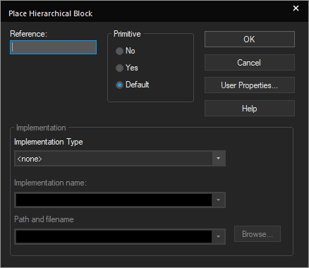
When you place a hierarchical block, you must specify a reference. However, the reference need not be updated if the hierarchical block is primitive. For example, you can specify the reference as Halfadd? when you place a hierarchical block. When you run the Annotate command, the reference of the hierarchical block is updated along with other parts. - Enter a name for the hierarchical block in the Reference text box.
- Choose Schematic View as the implementation type, in the Implementation Type list box.
- Type the name of the schematic folder in the Implementation Name text box.
- If the schematic folder is not part of the current project, specify the path to the schematic folder in the Path and Filename text box.
→ When you attach a schematic folder to a part or hierarchical block, you can specify a full path and filename in the Path and Filename text box. Although you can specify a library that has not been saved, do not descend into the attached schematic folder until the library that contains the schematic folder is saved.
→ If you do not specify a full path and file name in the Path and Filename text box, Capture expects to find the attached schematic folder in the same design as the part of hierarchical block to which it is attached. If the specified schematic folder does not exist in either the design or the library, Capture creates the schematic folder when you descend hierarchy on the part or hierarchical block.
For compatibility with future versions of Windows, the case of the path and filename specified are preserved.
→ If you attach external schematic folders or other files to hierarchical blocks in a design or parts in a library, ensure that you include the attachments when you pass the design or library to a board fabrication house or to another engineer. Attached schematic folders and other files are not carried along automatically when you copy or move a part, schematic folder, or schematic page to another library, design, or schematic folder. Only the pointers to the attached schematic folders and files—their names and the names of the designs or libraries that contain them—are carried along. - Click OK.
- Use the cursor to draw the boundaries of the hierarchical block on the schematic page.
Capture creates the new hierarchical block and automatically places the hierarchical pins according to the ports that exist in the attached schematic.
The implementation path must be empty if the Hierarchical Block or Hierarchical Part refer to the same schematic design.
Creating a Hierarchical block from a Verilog Model
In Capture, you can create hierarchical blocks from Verilog models for inclusion on your schematic page. Creating hierarchical blocks in this manner is generally termed "bottom-up" design.
To create a hierarchical block from a Verilog model, do the following:
- Open the parent schematic page in the schematic page editor.
- From the Place menu, choose Hierarchical Block. Alternatively, press ALT+p+h.
- Enter a name for the hierarchical block in the Reference text box.
- Select Verilog as the implementation type in the Implementation Type drop-down list box.
- Type the module name for the model in the Implementation name text box.
- Specify the Verilog file for which you want to create a hierarchical block in the Path and filename text box. Make sure the file is a Verilog type file (*.V).
- Click OK.
- Use the cursor to draw the boundaries of the hierarchical block on the schematic page.
Capture creates the new hierarchical block and automatically places the hierarchical pins according to the port list specified in the module section of the Verilog file.
If the port names in the Verilog model have both upper and lower case characters in their identifiers, the property Vlog_Uppercase is attached to the resulting hierarchical block. For more information about Vlog_Uppercase, see Verilog tab.
At this point, the hierarchical block is defined and ready to be wired in to the rest of the schematic.
Creating a Hierarchical Block from a VHDL Model
In Capture, you can create hierarchical blocks from VHDL models for inclusion on your schematic page. Creating hierarchical blocks in this manner is generally termed "bottom-up" design.
To create a hierarchical block from a VHDL model, do the following:
- Open the parent schematic page in the schematic page editor.
- Choose the Place – Hierarchical Block menu command.
- Enter a name for the hierarchical block in the Reference text box.
- Select VHDL as the implementation type in the Implementation Type drop-down list box.
- Type the entity name for the model in the Implementation name text box.
- Specify the VHDL file for which you want to create a hierarchical block in the Path and filename text box. Make sure the file is a VHDL type file (*.VHD).
- Click OK.
- Use the cursor to draw the boundaries of the hierarchical block on the schematic page.
Capture creates the new hierarchical block and automatically places the hierarchical pins according to the port list specified in the VHDL entity.
At this point, the hierarchical block is defined and ready to be "wired in" to the rest of the schematic.
Creating Parts
In Capture, you can create a part and add it to a new or existing library. The part may be a single part or a multiple-part package. It can contain graphics and IEEE symbols, which must be inside the part-body border, as well as text, which can be either inside or outside the part-body border. For any part that you create, you can also create a part convert.
Creating a part involves three tasks:
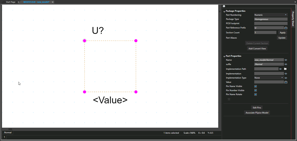
- Define the part properties in theProperty Sheet pane.
- Define the part body.
- Place pins on the part body.
You can use an existing part as a model for a new part by moving a copy of the part to a second library and then editing the copy. If you want to have the new part in the original library, rename the new part, then move it to the original library.
Creating Part Body
You define the part-body using the tools available on the tool palette. All of these tools are also available on the Place menu. Using the selection tool, you can select a placed object for editing.
You create a new part in the part editor. To create a new part, do the following:
- In the project manager, open a new
.olbfile. - Select the Library node in the project manager tree.
- Right-click a library name and choose New Part.
The New Part Properties dialog box is displayed.
- Specify the required values in each field in the New Part Properties dialog box.
- Click OK.
Part editor opens with an empty, rectangular visible part outline (the part-body border) visible. The part body border expands to accommodate the graphic elements of the part body, and pins are constrained to the part-body border.
-
To change the size or shape of the part-body border, select the border and drag the selection handles until the part-body border appears as you want it.
You can draw part bodies thicker than the pins and the rest of the part by adjusting the line style for the graphic objects you want to be thicker
Creating Part Shape
Before you begin drawing, you can specify default line and fill styles because all the lines and the shapes you draw adopt the current line style, and closed shapes adopt the current fill style. You can use a variety of line types or fill styles for any schematic page or part.
To change the snap to grid option, do the following:
- From the Options menu, choose the Preferences command
- Select the Grid Display tab.
You can set the option separately for the schematic page editor and the part editor.
To set a default line style, do the following:
- From the Options menu, choose the Preferences command and then select the Miscellaneous tab.
- Click the Line Style and Line Width list to view the options.
- Select one of the options and click OK.
Any lines or shapes you draw will have this line style.
To define a default fill, do the following:
- From the Options menu, choose the Preferences command.
- Select the Miscellaneous tab.
- Click the Fill Style list to view the options.
- Select one of the options and click OK.
Any closed shapes you draw will have this fill style.
To create the part body you use the drawing objects in the Place menu (or the Draw toolbar). These include line, polyline, rectangle, and arcs.
Notice that when you are in the part editor, most of the options on the Place menu are disabled.
To draw an object, do the following:
- From the Place menu, choose the appropriate drawing command or select the appropriate drawing command from the Draw toolbar.
- Use the mouse to draw the object.
To constrain the object by the orthogonality rules, press and hold the SHIFT key as you draw.
To edit line style or fill style of a placed object, do the following:
- Select an object.
- The Basic Attribute section appears in the Property Sheet pane.
- Select another line style or fill style and save the object.
Adding Text
You can add comment text, in the font of your choice, on a schematic page or a part. Use the text tool to document your schematic folder or to place the logic definition for a programmable logic device.
Adding Text
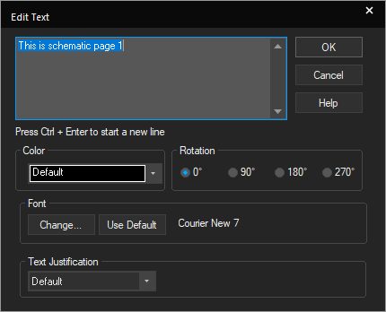
To add comment text to a schematic page, do the following:
- From the Place menu, choose Text.
The Place Text dialog box is displayed.
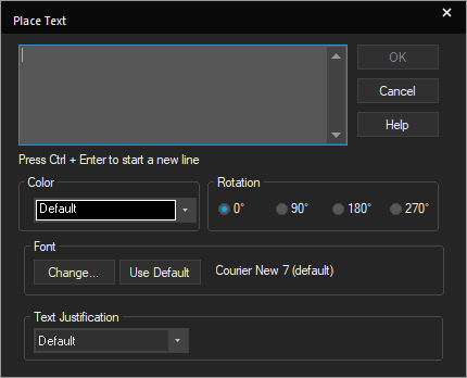
- Enter the text.
- Complete the dialog box selections—the font, color, or rotation.
- Click OK.
A rectangle representing the text is attached to the pointer. - Use the mouse to move the text.
- Click to place the text at the desired location.
- You can place multiple copies of the same text. Just click at each location where you would want the text. When you are through placing text, select the selection tool or press ESC.
- You can create multiple lines within a text object by pressing
Ctrl +Enter to create a new line. This is useful for creating piped PLD commands without having to place multiple lines of text. Piped SPICE commands must be placed on separate lines. -
A comment starting with @PSpice: is netlisted to PSpice during netlist creation only if it is placed in the root schematic.
Examples of single-line comment and multi-line comment starting with @PSpice: are:
- Single-line comment
@PSpice: R1 1 0 1k will be netlisted as R1 1 0 1k
- Multi-line comment
@PSpice: .autoconverge ITL1=1000 ITL2=1000 ITL4=1000 RELTOL=0.05 ABSTOL=1.0E-6 VNTOL=.001 PIVTOL=1.0E-10 .TEMP 125
will be netlisted as
.autoconverge ITL1=1000 ITL2=1000 ITL4=1000 RELTOL=0.05 ABSTOL=1.0E-6 VNTOL=.001 PIVTOL=1.0E-10 .TEMP 125
- Single-line comment
To add comment text in part editor, do the following:
- From the Place menu, choose the Text command.
The Edit Comment Text dialog box appears.
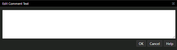
- Specify the text to place on the part page.
- Click OK.
The text is immediately attached to the cursor. - Click where you want to place the comment text.
- Select the selection tool or press ESC to complete placing the text.
Shortcut
Tool palette: 
To edit text display properties in a schematic page, do the following:
- Select the text.
- From the Edit menu, choose the Properties command.
- In the dialog box that appears, change the font, color, or rotation, then click OK.
Shortcut
Mouse: Double-click the text to edit.
To edit text display properties in part editor, do the following:
- Select the text.
- The Text Properties section appears in the Property Sheet pane.
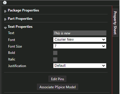
- Modify the font, color, or justification.
- Save the part.
Adding Pins
When you place a pin, you can describe it completely. To place pins, you need to be in the Part view of the part editor. If you want to place several identical pins that are not sequentially numbered on the part-body border, the Pin tool is ideal. You may place individual pins, or you may place an array of pins.
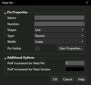
To place a pin, do the following:
- From the Place menu, choose Pin.
The Place Pin dialog box appears.
-
Edit the values as required.
Name The name can be up to 128 characters long and may include any character. If you place multiple copies of the pin and the name ends with a numeric component, the final numeric component increments by one with each successive pin you place.
If you are using Capture design with PCB Editor, ensure that the pin names do not exceed 255 characters.Number The pin number can be up to 32 characters long and may include any character. If you place multiple copies of the pin and the number ends with a numeric component, the final numeric component increments by one with each successive pin you place.
Shape Select from the given options: CLOCK, DOT, DOT CLOCK, LINE, SHORT, SHORT CLOCK, SHORT DOT, SHORT DOT CLOCK and ZERO LENGTH. If you select a pin type of POWER, the pin shape is set to ZERO LENGTH automatically.
You can also specify a user-defined pin shape if the pin shape is available in the CAPSYM.OLB library.Type Select from the given options: 3STATE, BIDIRECTIONAL, INPUT, OPEN COLLECTOR, OPEN EMITTER, OUTPUT, PASSIVE, and POWER. The Design Rules Check tool uses pin type to check electrical rules.
Width Select Scalar or Bus. If you choose Bus, the pin name must be of the form basename[m..n] where m..n specifies a range of decimal integers representing the number of bus members.
Visibility If you are placing a power pin, you can select the Pin Visible check box to cause the pin to cancel the pin's global attribute. This is useful if you want to create an isolated power net. If a power pin is visible, it must be connected to a wire. For more information on power and ground pins or Isolating power or ground, see Power and Ground Symbols.
Some netlist formats do not accept certain characters in pin names. Always check the description for the netlist format you want to use.
- Define the pin and click OK.
The pin appears attached at the periphery of the part. - Use the mouse to move the pin to its intended location and click to place it.
The pin appears in the selection color until you move the pointer. - If you want to place additional pins, repeat step 1-4.
As you place successive pins, any final numeric component of the pin name or pin number is incremented by one.
Placing a pin in one view (normal or convert), places an identical pin in the other view to prevent the parts from getting out of sync. The same is true about deleting pins. Changing the name of a pin in one view does not change it in the other. However, if you change a pin number in one view, Capture changes the pin number in the other view so the two views are in sync. - If you need to edit pin properties:
- Select the pin.
- The Pin Properties section appears in the Property Sheet pane.
- Modify the properties and save the part.
- When the pins are placed, use the selection tool, or press ESC to dismiss the pin tool.
When placed, pins are constrained to the part-body border. If the edge of the part-body coincides with this border, the pins are directly attached to the part-body. - If the part body does not coincide with the part-body border, draw a line from the connection point of the pin to the part body.
You may need to temporarily turn off the Pointer snap to grid option (Options – Preferences – Grid Display) while you draw the line.
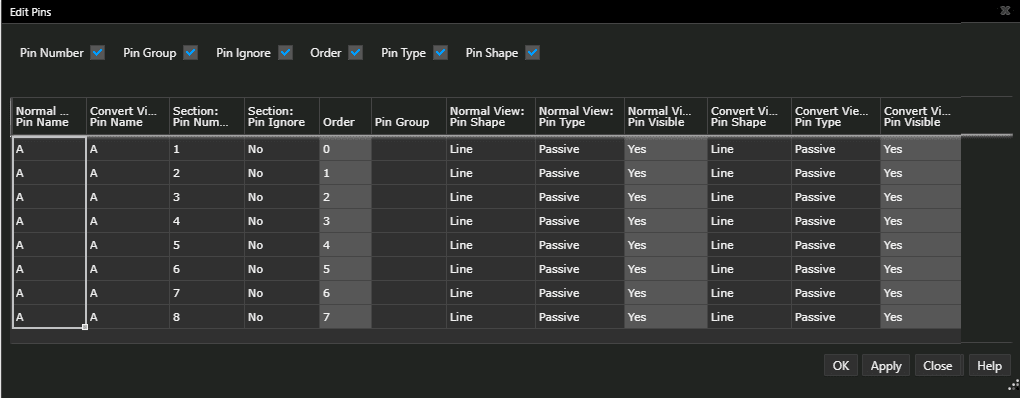
You can edit every pin in the package using the Edit All Pins dialog box (Edit – Edit Pins).
Shortcut
Tool palette: 
Adding an Array of Pins
If you wish to create multiple identical pins that are numbered sequentially on the part body border, you can place an array of pins. A pin array is defined by a single set of electrical characteristics. The Pin tool is ideal for creating multiple pins with identical properties and placing them so that the pin numbers and names are sequentially arranged on the part body border. You can also use the Pin Array command for placing large numbers of pins even though the properties or pin numbers vary.
To place an array of pins, do the following:
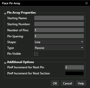
- From the Place menu, choose Pin Array.
The Place Pin Array dialog box appears.
-
Modify the values as required.
Starting Name The starting name can be up to 128 characters long and may include any character. The leftmost or upper pin of the array is assigned the starting name. If the starting name ends with a numeric component, that component increments by the increment amount from top to bottom and from left to right. Starting Number The starting number can be up to 128 characters long and may include any character. The leftmost or upper pin of the array is assigned the starting number. If the final component of the starting number is numeric, the pin numbers change by the increment amount from top to bottom and from left to right. Number of Pins An integer value. Pin Spacing A positive value. The distance between the pins is measured in grid units. Shape Select from the given options: CLOCK, DOT, DOT CLOCK, LINE, SHORT, ZERO LENGTH. If you select a pin type of POWER, the pin shape automatically is set to ZERO LENGTH. Type Select from the given options: 3STATE, BIDIRECTIONAL, INPUT, OPEN COLLECTOR, OPEN EMITTER, OUTPUT, PASSIVE, POWER. Pin type is used by the Design Rules Check tool to check electrical rules. Pin Visible Specify the pin visibility when the part is placed on the schematic page. Only power pins can be set to not visible. Pin# Increment for Next Pin
Specify the increment for the next pin number in the pin array.
Pin# Increment for Next Section
Specify the increment between pin numbers for the next section. This is valid only for homogeneous parts. - When you have defined the array, click OK.
The array is attached to the periphery of the part; the part body border automatically increases in size, if necessary. - Use the mouse to move the array to its intended location and click to place it.
The array appears in the selection color until you move the pointer. - Select the selection tool to dismiss the pin tool.
- If the part body does not coincide with the part body border, draw a line from the connection points of the pins to the part body.
You may need to temporarily turn off the Pointer snap to grid option (Options – Preferences – Grid Display) while you draw the lines.
Shortcut
Tool palette: 
Connecting Pin to Non-rectangular Part Body
To connect a pin to a non-rectangular part body, do the following:
- Place the pin on the part body border.
- From the Options menu, choose Preferences.
- Select the Grid Display tab.
- In the Part and Symbol Editor group box, deselect the Pointer snap to grid option.
- Click OK.
- Draw a line between the pin and the part body.
- If the line does not look like a pin, edit the line style and width.
- From the Options menu, choose Preference.
- Select the Grid Display tab.
- In the Part and Symbol Editor group box, select the Pointer snap to grid option.
- Click OK.
The size of a part or a symbol is limited to 32 by 32 inches.
Shared Pins
Both homogeneous and heterogeneous parts may have shared pins. A common use of shared pins is for supply (power or ground) pins, which are referred to in Capture as 'power pins'.
On heterogeneous parts, power pins can be visible on every part in the package. If the pins are visible, they must be placed on at least one part in the package, and that part must be placed in the design for the power connections to appear in the netlist. Invisible power pin types must also be in a part that is placed in the design for them to appear in a netlist.
On homogeneous parts, power pins appear on every part in the package. The pin names are filled in automatically, but you must specify the pin numbers. For the pins to be shared, verify that both the pin names and pin numbers are the same for every part in the package.
- If you place the same pin on multiple parts in a package, you can inadvertently short two nets. Use caution to avoid this problem, and always run Design Rules Check before creating a netlist.
- Pin names are shared, but pin numbers are not.
Pin Shapes
When you place pins on a part body, you can specify the shapes of the pins. You can use the predefined system-defined Pin shapes or you can create your own pin shapes.
System-Defined Pin Shapes
Capture provides a list of system-defined pin shapes that you can use when you create a new part or edit the pins shapes on an existing part.
|
|
Clock |
|
|
Dot |
|
|
Dot-Clock |
|
|
Line |
|
|
Short |
|
|
Short Clock |
|
|
Short Dot |
|
|
Short Dot-Clock |
|
|
Zero length |


User-Defined Pin Shapes
You can create your own pin shapes in Capture. You can then use these pin shapes on new or existing parts.
To create a pin shape, do the following:
- Open the CAPSYM.OLB library from the installation path: <Installation Directory>\tools\capture\library\capsym.olb.
- Select the library (capsym.olb) in the project manager.
- Choose Design – New Symbol.
Or
Right-click the library (.olb) and choose New Symbol. - Enter a name for the new pin shape.
A symbol name length cannot exceed 31 characters. - Choose the Pin Shape option in the Symbol type group and click OK.
The Part Editor page opens with an empty rectangle defining the boundary of the pin shape. - Draw the pin shape using the available shapes on the Draw toolbar.
The new pin shape is now available in the selected library.
You can now use this pin shape by placing it on a part.
Points to Remember
When creating user-defined pin shapes:
- You can choose Line, Arc, Polyline, Bezier curve, Rectangle, Ellipse, Elliptical arc shapes to create a user-defined pin shape around a dot connection point.
- The bounding box of the pin shape determines the length of the pin. If the bounding box does not completely enclose the graphics, you may see your pin offset from the boundary of the symbol. For a correct adjustment, ensure that the bounding box completely encloses the graphics.
- The Capture Part and Schematic Page editors require a dot connection point to be on the grid. For the pin start point to touch the body of the symbol, you must keep the end points on the grid.
- You should not draw objects enclosing the dot connection point. That may not show the pin shape correctly on the Capture Part and Schematic Page editor.
IEEE symbols and pictures are not supported in user-defined pin shapes.
When adding user-defined pin shapes to parts in your designs:
- The pin shape must be available in the CAPSYM.OLB library in the path %CDSROOT%\tools\capture\library\capsym.olb.
If you create your pin shape in a user-defined library, you need to copy that symbol into the CAPSYM.OLB library.
Capture reads the user-defined pin shapes from this location and populates the pin shape names in the Shape cell of the Pin Properties dialog in Part Editor. - If you place a new part in a design that has pin shapes assigned to pins, Capture searches for the pin shapes in the CAPSYM.OLB library. When the part is placed on the design and the pin shapes are found in the CAPSYM.OLB library, the pin shapes are cached to the design cache. Once you save the design, the pin-shapes are read from the design cache.
- If a pin shape is not available in the CAPSYM.OLB library, the default pin shape, which is a line, is displayed on the part.
- If you run the Replace Cache command on a user-defined pin shape, for instance A with B in the design, all instances of the user-defined pin shape A are replaced with B in the design, and the Pin Shape property on the pins is updated to the new pin shape value. This property is an instance override. At any time, if you want to revert to the library-level pin shape value, you can use the Delete property in the Property editor and it will delete the instance override and this is reflected on the schematic. However, if you edit a part, it continues to show the part level user-defined pin shape and not the instance override that exists in the schematic.
Pin Types
|
3 State |
A 3-state pin has three possible states: low, high, and high impedance. When it is in its high impedance state, a 3-state pin looks like an open circuit. For example, the 74LS373 latch has 3-state pins. |
|
Bidirectional |
A bidirectional pin is either an input or an output pin. For example, pin 2 on the 74LS245 bus transceiver is a bidirectional pin. The value at pin 1 (an input) determines the active type of pin 2, as well as others. |
|
Input |
An input pin is one to which you apply a signal. For example, pins 1 and 2 on the 74LS00 NAND gate are input pins. |
|
Open Collector |
An open collector gate omits the collector pull-up resistor. Use an open collector to make wired-OR connections between the collectors of several gates and to connect with a single pull-up resistor. For example, pin 1 on the 74LS01 NAND gate is an open collector gate. |
|
Open Emitter |
An open emitter gate omits the emitter pull-down resistor. The proper resistance is added externally. ECL logic uses an open emitter gate and is analogous to an open collector gate. For example, MC10100 has an open emitter gate. |
|
Output |
An output pin is the one to which the part applies a signal. For example, pin 3 on the 74LS00 NAND gate is an output. |
|
Passive |
A passive pin is typically connected to a passive device. A passive device does not have a source of energy. For example, a resistor lead is a passive pin. |
|
Power |
A power pin expects either a supply voltage or ground. For example, on the 74LS00 NAND gate, pin 14 is VCC and pin 7 is GND. It is not a good idea to use overbars above power pin names; if you do, any netlists that you create will have invalid power pin names. Power pins are invisible. |
Creating a Part Convert
You can store a part convert with a library part, then place either the normal view of the part or its convert.
To add a convert while you are creating a part, do the following:
- Select the library project manager window From the Design menu of the library's project manager window, choose New Part.
The New Part Properties dialog box is displayed. - Select the Create Convert View check box.
- Modify the remaining properties and click OK.
- The Convert tab appears next to the Normal tab in the part editor.
Creating a Part Alias
A part may come with several speed ratings or be made by several manufacturers. If all the variations have a common graphic and PCB footprint, you may not have the time and space to create and store a different library part for each variation. Instead, you can create a single library part and assign it multiple aliases.
To create a part alias, do the following:
- In the project manager, select the design (.OLB) file.
- From the Design menu, choose New Part.
The New Part Properties dialog box opens. - Click the Part Aliases button.
The Part Aliases dialog box opens. - Click the New button.
The New Alias dialog box opens.
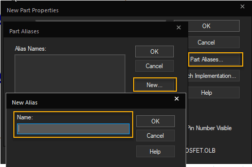
- Specify the name of the alias and click OK.
- Click OK, as needed, to close the remaining open dialog boxes.
To add or update a part alias, do the following:
- Select a part.
- In the Package Properties section of the Property Sheet pane, click the Update button next to the Part Aliases field.
The Update Alias dialog box opens. - Click the plus icon.
A new row appears.
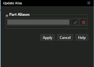
- Specify a new alias and click the check mark button to add this alias.
- Click the Apply button.
Creating a Part from a Spreadsheet
Use the New Part Creation Spreadsheet dialog box to create new parts (multi-section/single-section). This dialog box has an interface similar to a spreadsheet, where you can copy the content from a part data sheet.
Before you copy and paste part information (pin number, pin name, pin type, and so on) from a data sheet, ensure that you arrange the part information in the same column header format/sequence as it appears in the New Part Creation Spreadsheet.
To create a new part from spreadsheet, do the following:
- Select a library (
.OLB) file that will contain the new part in the project manager. - Select the Design menu and choose the New Part from Spreadsheet command. Alternatively, right-click the library file and select New Part From Spreadsheet.
The New Part Creation Spreadsheet is displayed. Each row in New Part Creation Spreadsheet corresponds to a pin while each column corresponds to properties associated with the pin. The property names are listed as the column header.
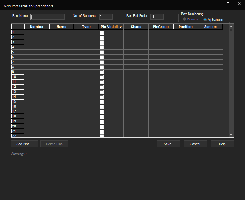
- Specify a name for the new part in the Part Name text field.
-
To create a multi-section part, specify the number of sections you want to have in your new part in the No. of Sections text field.
The New Part Creation Spreadsheet creates single-section parts, by default.The Section property column changes to a list box displaying the number of sections you specified in the No. of Sections text field. Number of sections cannot be less than one.
-
Specify a part reference prefix for the part in the Part Ref Prefix text box.
-
Select Numeric or Alphabetic in the Part Numbering group box.
If you select Alphabetic, an alphabet (between A to Z) will be added as a suffix to the current part reference for each of the new parts.
If you select Numeric, a number (between 1 and 1024) will be added as a suffix to the current part reference for each of the new parts.
The Section property column changes based on your selection in the Part Numbering group. For example, if Alphabetic is selected, the Section property column displays A. - Specify a pin number in the Number property column.
To sort on any property, double-click its name in the column header. - Specify a name for the pin in the Name property column.
- Select the type of pin from the Type property list.
- Select the Type cells for multiple pins simultaneously using the
Shift + downarrow keys and then entering the pin type. The selected Type cells get populated with the pin type of your choice.
Alternatively, you can:
- Select the Type cells for multiple pins simultaneously using the
Shift +click, then press theCtrlkey, and then select a pin type of your choice from the list box.
The selected Type cells get populated with the pin type of your choice. - Click the first cell of the range, and drag to the last cell, and then enter the pin type of your choice.
The selected Type cells get populated with the pin type of your choice.
(You can use these methods to make selections in the Shape, Position, and Section property drop-down lists also).
- Select the Type cells for multiple pins simultaneously using the
- Select a shape for the pin from the Shape property drop-down list.
You can hide or unhide a property column in the New Part Creation Spreadsheet. To do this, right-click the property column header you want to hide and select Hide from the pop-up menu. The selected property column will now not appear. To unhide a property column, right-click the property column header next on the right-hand side of the hidden property column and select Unhide from the pop-up menu. The hidden property column appears in the New Part Creation Spreadsheet.
Alternatively, you can unhide a property column by:
- Double-clicking the column handle (
 ) of the property column header.
 - Dragging the column handle of the property column header.
You can change the order in which the property columns and rows appear in the New Part Creation Spreadsheet. To do this, select the property column/row header you want to move and drag and drop it to the location where you want it in the New Part Creation Spreadsheet. - Double-clicking the column handle (
- Specify a value for a swappable (input) pin of the part in PinGroup text field.
- Select the position where you want this pin to appear in the part for the Position property drop-down list.
- Select a section number you want to associate with the pin from the Section property drop-down list.
You can select Section cells for multiple pins simultaneously using theShift +down arrow keys and enter the section number. Alternatively, you can:
- Select the Section cells for multiple pins simultaneously using the
Shift +click, then press theCtrlkey, and then select a section number of your choice from the list box. The selected Section cells get populated with the section number of your choice. - Click the first cell of the range, and then drag to the last cell, and then enter the section number of your choice. The selected Section cells get populated with the section number of your choice.
You can select alternate Section cells for multiple pins simultaneously with the
Ctrl +click action and then by entering the section number. The pins are added in the same order in the new part as the order in which the pins appear in the spreadsheet. - Select the Section cells for multiple pins simultaneously using the
-
Click the Save button to save the new part.
If any warnings are generated during the save operation, a message appears asking you whether you want to view the warnings. -
To view the warnings, click the View Warnings button. The New Part Creation Spreadsheet expands and displays a grid showing warnings messages.
If you select the Continue button, the part is saved as is. -
Click the Hide Warnings button to hide the warning messages or the Show Warnings button to display the warning messages again.
If the new part you created contains one part per package, the part created is homogeneous otherwise the part is heterogeneous.
To add a pin, do the following:
- In the New Part Creation Spreadsheet dialog box, click the Add Pins button.
The Add Pins dialog box appears.
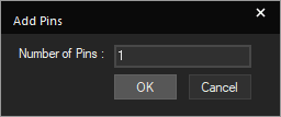
- Specify the number of pins you want to add in the Number of Pins text field.
- Click OK.
The desired number of blank rows are added at the end of the current row set in the New Part Creation Spreadsheet dialog box.
To delete a pin, do the following:
- Select a row in theNew Part Creation Spreadsheet dialog box.
- Click the Delete Pins button.
A message appears asking you to confirm the deletion. - Click OK to confirm deletion.
The selected row is deleted from the New Part Creation Spreadsheet dialog box.
Creating a Heterogeneous Part
To create a heterogeneous part in a library, do the following:
- Open the library and choose New Part from the Design menu.
- Specify the part name.
- Set the number of parts in the package.
- Select Heterogeneous in the Package Type group box.
- Enter the PCB Footprint if you want to assign one to the part at this time.
- Click the OK button.
Capture creates a the logical part with the reference designator U?A. - Draw the part body and add the pins.
- To get to the B package, choose Next Part from the View menu, or press
CTRL+N.
Capture displays the U?B part for you to edit. - Again, draw the part body and add the pins.
- Repeat this process until all the logical parts are created.
After creating the logical parts of your heterogeneous part in the library, you need to assign a unique property to each one. For example, create a property named PACKAGE.
Assigning Unique Property to a Part
To add a unique property to a heterogeneous part, do the following:
- Add a user-defined property in the Part Properties section of the Property Sheet pane.
- Open the schematic and place the A, B, C, and other logical parts of your heterogeneous parts appropriately in your design.
- After you place each logical part, double-click the part to open the property editor.
- Edit the value of the
PACKAGEproperty shown in the spreadsheet. - Leave the Value of 1 on that property for each logical part of the first set you place; assign a Value of 2 to each logical part in the second set, and so on.
Capture uses these values to group the heterogeneous parts correctly when assigning reference designators.
Assigning Reference Designators
To annotate the design, do the following:
- Add the property name to the combined property string in the Annotate dialog box.
Capture uses this property and the assigned values to annotate the parts correctly in the design. - In the project manager, select the design name, and choose the Tools – Annotate menu command.
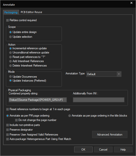
- Select Update entire design.
- Select Unconditional reference update,
- Select Incremental reference update, if you have already partially annotated your design.
- Type
{PACKAGE}in the Combined property string box.
This gives you a combined property string like {Value}{Source Package}{PACKAGE}. - Click OK,
Capture assigns the appropriate reference designators to all your parts in the design including the heterogeneous parts.
Editing Parts
If you have a library part that is nearly perfect, you can tailor the original part to suit your project requirements. You can edit the part properties and change its graphical representation or its pins.
To edit a library part, do the following:
- Open the library containing the part.
- In the project manager, double-click the part.
The part editor opens with the part displayed. - Make changes to the part body definition (such as graphics, text, and images) using the Property Sheet pane.
- To make any changes to pins, select the required pin, and modify its properties using the Property Sheet pane.
You can move pins after you select them. You can also move pin names or pin number text when you are editing a library part. - Choose File – Save.
To edit a part instance on a schematic page, do the following:
- Select the part in the schematic page editor.
- From the Edit menu, choose the Part command.
The part editor opens with the selected part displayed. - Edit the part as required.
- Choose the File – Close menu command.
The Save Part Instance dialog displays:
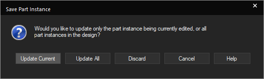
- Update Current creates a new part in the design cache. The new part has no link to the original library.
- Update All replaces the old part in the design cache with the newly edited part and breaks the link with the original library.
The part editor window closes and the updated part appears in the schematic page editor.
The Edited Part
- The edited part does not exist in a library, so the only way to place a copy of it is to use the Copy and Paste commands on the schematic page editor Edit menu.
- The edited part has no link with the original library, so it is not affected by the Update Cache command. To restore its link with the original library, choose the Design – Replace Cache menu.
- When you open the part editor from the schematic page editor, the part you are editing cannot be selected on the schematic page. The part can only be selected after you close the part editor window,.
- You can move pin names and pin number text when you are editing a part instance on a schematic page.
- When you edit the graphic representation of a part on a schematic page, you break the connection between the part and the library. To reverse your edits, use the Design – Replace Cache menu command.
Moving Pin Name and Pin Number
You can move pin names and pin numbers only when you are editing a part instance on a schematic page.
- To move a pin name or pin number, select the pin name or number text and drag it to the desired location.
- To reset a pin name movement, select the pin name text you had moved and from the Edit menu, choose Reset Location, then Pin Name.
- To reset a pin number movement, select the pin number text you had moved and from the Edit menu, choose Reset Location, then Pin Number.
To rename a part, do the following:
- In the project manager, select the part.
- From the Design menu, choose Rename.
The Rename dialog box appears. - Specify the new name and click OK.
Part Properties
When you need to edit properties for several parts, you can save time by using the spreadsheet editor, the Update Properties command, or the Export Properties command.
After you have added properties to a part on a schematic page, its properties no longer match the properties of the same part residing in the library. This part is unique in that it has properties assigned specifically to it that are not inherited from the library part definition.
- If you add a user-defined property to one part in a homogeneous multiple-part package, all the parts in the package inherit the property and its value.
- If you add a user-defined property to one part in a heterogeneous multiple-part package, the other parts in the package are not affected.
You can also edit properties on part packages, in which case the changes appear on every part in the package, and on every part instance.
When you are editing the properties of a library part in the part editor, you use the Property Sheet pane. You can add or remove user-defined properties or change the values for the following properties:
- Part Value
- Part Reference
- PCB Footprint
- Power Pin Visibility
- User Properties
Assigning Properties to a Part
Assigning Reference Designator
All the parts of the same type placed on a schematic are assigned the same part reference. For example, C? is assigned to all the capacitors. Regardless of the ultimate purpose of the design, each part needs a unique identifier.
- To assign reference to parts individually, right-click a part and choose Edit Part.
The part opens in the part editor, where you can edit the reference designator.
For PCB designs, create a swap file or packages for swapping to use with the Backannotate tool.
- To uniquely identify parts, choose the Tools – Annotate menu command on the menu.
Annotating parts assigns unique alphanumeric part references.
For PCB designs, it assigns individual parts to a package and assigns unique pin numbers to each part in a multiple-part package.
References are assigned in order—from top to bottom and left to right. Parts located at the top of the page have the lowest numerical designation. If two parts share a vertical coordinate, the part further to the left has the lower numerical designation. If you add parts after you have assigned part references, you can easily remove part reference assignment and run the Annotate command again.
- Use the Annotate command after you have placed all the parts and before you use any other Capture tools.
See Design Annotation for an overview of the design processing tools. - Update references incrementally, so that previously-assigned part references are not changed.
- Capture automatically updates either instances or occurrences depending upon the type of the design. In general, you can update instances for FPGA and PSpice projects, and update occurrences for PCB and schematic projects.
- To preserve a reference designator during annotation, right-click a part on the schematic page and choose User Assigned Flag - Set. Alternatively, you can open the part in Property Editor, right-click Reference, and choose User Assigned Flag – Set. The User Assigned Flag is set by the tool if the reference designator is changed using the Property Editor or Schematic Editor or through Backannotation.
If the property does not exist on the occurrence, the User Assigned Flag is set for the instance and is used for all occurrences of that part unless the property is explicitly overridden on the occurrence. If you want to set the User Assigned Flag for the occurrence value, set the property on the occurrence from the property editor and then set the flag.
Changing Visibility of Pin names and Numbers
To globally change the visibility of pin names or pin numbers, do the following:
- In part editor, select a part.
The Part Properties section in the Property Sheet pane appears. - Select the Pin Name Visible property to control pin name visibility.
- Select the Pin Number Visible property to control pin number visibility.
- Save the part to apply the changes.
Property Tables
You can assign many properties to your library parts.
Some of the properties used in schematic to layout flow are listed in the following table:
|
Part Property Name |
Example Value |
Description |
|
|
|
If the value is YES, the part such as an edge connector is permanently fixed to the board. |
|
|
|
An integer value that assigns the part to a group for placement. The value must be numeric, and between |
|
|
|
Used to designate a component as the key component in a given group. The key component is placed first with all the other components in the group placed in close proximity. |
|
|
|
Part location on the board as |
|
|
|
If the value is |
|
|
|
Part rotation in degrees and minutes counterclockwise from the orientation defined in the Layout library. Use a period (.) to separate degrees and minutes. |
|
|
|
Determines which side of a board a part will reside on, |
|
|
|
An explicit definition of the footprint name to attach to the component. |
|
|
|
Comma-delimited list of alternative footprints to attach to the components to ease switching between footprints. |
|
|
|
Identifies gate swapping restrictions within a component. To be swapped, two gates must belong to the same gate group. |
|
|
|
A customer part number that is generally unique for each customer and identifies the exact part, including the manufacturer and case type. |
|
|
|
Defines non-wired pins, such as unusual voltages as belonging to a particular net. |
|
|
|
Sets the track width, leaving |
|
|
|
If the value is |
|
|
|
Sets the maximum track width. |
|
|
|
Sets the minimum track width. |
|
|
|
Identifies grouped nets. Use this to select or color nets as a group in the layout editor for editing or routing. |
|
|
|
Integer between |
|
|
|
Assigns a net to a plane layer. Values are |
|
|
|
Specifies the reconnect rules for each type of reconnect. Values are |
|
|
|
Restricts the layers on which this net can route. |
|
|
|
Net spacing for one or more layers. |
|
|
|
If the value is |
|
|
|
Via types allowed for net. |
|
|
|
Track width value assigned to the |
|
|
|
Net width for one or more layers. |
Editing Part Properties
You can rename and delete a part property in every part instance that contains the property for an entire design.
To rename a part property, do the following:
- In the project manager, select the design file or the schematic page.
- Choose the Edit – Rename Part Property menu command.
The Rename Part Property dialog box is displayed. - In the Find User Property text field, specify the current property name.
- In the Replace with User Property text field, specify the new property name.
- Click OK.
To delete a part property, do the following:
- In the project manager, select the design file or the schematic page.
- Choose the Edit – Delete Part Property menu command.
The Delete Part Property dialog box appears. - In the Property Name text box, specify the property name.
- Click OK.
Updating Properties using an Update File
To add specific information to a part, such as stock number or supplier, you can add a property and set the property value in the library. When you place the part in a project, the information is available.
You can edit parts individually in the part editor. To update properties of a number of parts simultaneously, use the Update Properties command.
Before you run the Update Properties command, create an update file as described in Update File.
To identify the parts to update, you can specify an identifying property or combination of properties called a combined property string. For each combined property string you use, you must create a separate update file and run the Update Properties command.
To update part properties, do the following:
- In the project manager, select schematic folders or schematic pages if you want to process only a part of the design.
To process the entire design, do not select the schematic folders or schematic pages. - Choose the Update Properties menu command.
The Update Properties dialog box appears. - Verify that the dialog box options are set as required.
For example, you specify, among other things, whether you are updating parts or nets, whether you want to overwrite existing property values, and the name and location for the update file. Unless you select the button to unconditionally update the property, properties that currently hold a property value are not updated. - In the Property Update File box, enter the name and location of the update file.
OR
Use the Browse button to navigate to the file. - Click OK.
- If you edit a Capture library, assign a new library name so that the changes made are not overwritten when you upgrade or update your software.
- Capture preserves the case of part names and net names, but ignores the case when comparing names for electrical connection.
- Capture report files are text files and can be opened in any text editor. You can use the tab alignment capability of your word processor to line up reports correctly. Spreadsheets automatically align the columns of Capture-generated report files.
Design Cache
When you place the first instance of a part in a project, a copy of the part is created in the design cache. The design cache stores a copy of every part used in the design similar to an embedded library. All instances of the part normally refer to this copy in the design cache.
A cache part also retains a link to the library part on which it is based, so you can update or replace all of the parts in the design cache to synchronize them with the parts in the libraries.
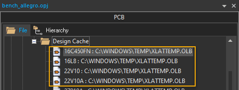
The project manager updates the display of the design cache every time you open the cache. You can click the Design Cache node to close or open the design cache, and run commands to replace or update parts in the cache.
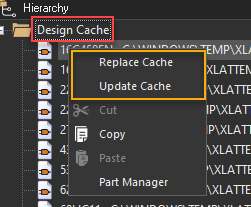
Cache Handling Commands
You can replace a selected part in the design cache based on its current definition with a different part in any library using the Replace Cache command. You can also update selected parts in the design cache based on their current definitions in their original libraries using the Update Cache command. The Update Cache command works when one or more parts are selected. You can also select all the parts.
When you copy pages from one design or library to another, parts displayed on the copied pages may appear different due to differences in each design or library cache. If a part is not already present in the destination design cache, Capture copies it from the cache of the source design. Otherwise, it continues to use the existing part in the cache of the destination design.
When you use the Replace Cache or Update Cache command, all the properties of the part are retained, but the pin reflects the properties of the library part. This means you lose any changes made to pin properties after the part was placed, including those made by the Back Annotate or the Annotate tools.
To modify a part's link to the library—part name, path, and library, use the Replace Cache command. The Update Cache command only brings in the new data when the path has not changed and the part is modified in the library after it is placed on the schematic. If the path and library names do not change, the Replace Cache command reloads the part definition into the design. However, if the Update Cache command finds that the part name and the library names are the same, it does not bring in part changes.
The Replace Cache and Update Cache commands are quite similar, but they have the following differences:
- You can modify the part’s link to the library, part name, path, and library, with Replace Cache; you cannot modify the part’s link with Update Cache.
- If you move a library after you place a part, the connection between the part and its library is broken. In this case, the Update Cache command will not find the library; you will need to use the Replace Cache command and specify the new path to the library.
- Using Replace Cache, you can replace multiple parts selected in the design cache with a single part.
- Using Update Cache, you can update multiple parts at a single instance.
The following table lists the impact of the Update Cache and Replace Cache commands on various design elements and attributes:
|
|
Update Cache command |
Replace Cache command |
||
|---|---|---|---|---|
| Preserve schematic properties |
Replace schematic properties without preserve Refdes |
Replace schematic properties with preserve Refdes |
||
| Part (Symbol) Graphics and Pins |
Updated | Updated | Updated | Updated |
| Part’s library level property values |
Updated if property edited on schematic. |
Updated if property edited on schematic. |
Updated | Updated |
|
Part’s schematic |
Preserved | Preserved | Updated | Updated |
| Part’s reference designator reference values |
Preserved | Preserved | Updated | Preserved |
| Pin properties values |
Updated if property value edited on schematic. |
Updated if property edited on schematic. |
Updated | Updated |
| Package Level properties values (such as PCB Footprint) |
Preserved | Preserved | Updated | Updated |
| Display location settings & coordinates for pin properties |
Updated | Updated | Updated | Updated |
| Display location settings & coordinates for part properties |
Preserved | Preserved | Updated | Updated |
When you use these commands with the option to preserve schematic part properties, the part retains all the instance and occurrence properties. All the changes made to pin properties after the part was placed are retained, including those made using the Back Annotate or Annotate commands.
Replacing and Restoring Parts
Use the Replace Cache command to replace or restore parts in a design.
To replace a part throughout a design, do the following:
- From the design cache, select the part you want to replace.
- Choose the Design – Replace Cache menu command. Alternatively, right-click and choose Replace Cache.
The Replace Cache dialog box is displayed. - In the dialog box, enter the name of the replacement part and the library that contains it.
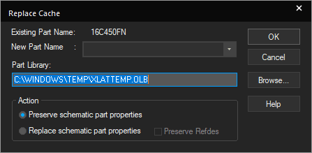
- Select the Replace schematic part properties action to completely replace the part and its properties. Otherwise, use the default action to preserve schematic part properties.
- Click OK.
- When the project manager appears again, double-click on the design cache to verify that the replacement part is listed instead of the original part.
- Click Cancel to return to the project manager.
Replace Cache
The part name and the library and path are listed in the dialog box that appears.
Restoring Parts in a Design
When you delete a part, you also delete all of its properties. However, you can restore the part and the properties of the part instance using the Replace Cache command. The pin properties, though, are not restored.
You can also use the Replace Cache command to undo edits to a part on a schematic page and restore the part's link to its library.
Synchronizing Parts
When you place a part in a design and that part is modified in the library, you need to update the design so that the modified part reflects the changes you have made in the library. To update the part in the design, yo use the Design – Update Cache menu command. When you use the
Update Cache command, the part properties are retained; however, the pin properties of the part instance are lost.
To update a part in the design cache, do the following:
- In the part editor, edit the parts in the library as required.
- Open the project manager window for the design.
- Select the parts in the project manager.
- Choose Design – Update Cache command.
The design cache and all part instances are updated to match the library parts.
Part Packages
Parts are the basic building blocks of a design. For PCB designs, part may represent one or more physical components; or it may represent a function, a simulation model, or a text description for use by an external application. The behavior of a part is described either by a SPICE model, an attached schematic folder, or HDL statements.
Parts in PCB designs usually correspond to physical objects—gates, chips, connectors, and so on—that come in packages of one or more parts. Multiple-part packages are physical objects that comprise more than one part.
Each logical part consists of graphics, pins, and properties that describe it. As you place the parts in a package to suit your design requirements, Capture maintains the identity of the part package for back annotation, netlisting, bills of materials (BOM), and the processes that require it. Parts inherit this information from the package.
When you place a part on a schematic page, you actually create an instance of the part. A part instance is like a snapshot of the part in the library because it inherits all the properties of the library part. After a part instance is placed on the schematic page, you can edit the properties of that instance without changing the properties of any other instance. The instance values of those properties supersede the values of any identical properties that exist on the library part.
When using multiple-part packages in your design, you must either make all the shared pins visible and connect them to power and/or ground nets, or make them all invisible, in which case they are connected according to their pin names.
Creating a Package
At the time of creating a part, you can specify packaging information to mark it as a package. The parts in a package may have different pin assignments, graphics, and user properties. You can also change it in the Package Properties section of the part editor.
To create a multiple-part package, do the following:
- Open the library to which the part is to be added.
- Choose Design – New Part.
The New Part Properties dialog box appears.
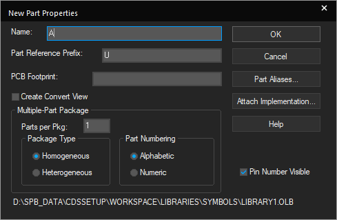
-
In the Parts per Pkg field, specify the number of parts in the package.
- Select the package type as Homogeneous if all the parts in the package are same. Else, select Heterogeneous.
If all the parts in a package are identical except for the pin names and numbers, the package is homogeneous. If the parts in a package have different graphics, numbers of pins, or properties, the package is heterogeneous.
For example, a hex inverter is homogeneous: the six inverters are identical, except for their pin numbers. A relay, which has a normally opened switch, a normally closed switch, and a coil, is heterogeneous as the three physical parts differ in graphics, number of pins, and properties. - Click the Attach Implementation button to display the Attach Implementation dialog box where you can attach a schematic folder to create a hierarchy.
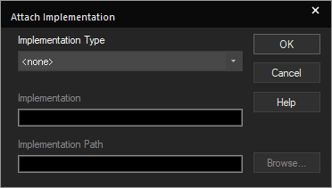
- Select Schematic View in the Implementation Type field.
-
Specify the name of the schematic folder in the Implementation field.
-
If the schematic folder is not in the current project, specify the library or path name of the schematic folder.
When you attach a schematic folder to a part or hierarchical block, you can specify the library path and file name. If you do not specify a full library path and file name, Capture expects to find the attached schematic folder in the same design as the part of hierarchical block to which it is attached. If the specified schematic folder does not exist in either the design or library, Capture creates the schematic folder when you descend the hierarchy on the part or hierarchical block. For compatibility with future versions of Windows, Capture preserves the case of the path and filename as you specify them in the Library text box.
If you attach a schematic folder to a homogeneous part, it is attached to each part in the package, not the package itself. You cannot attach a schematic folder to a heterogeneous part.
- Click OK to close the Attach Implementation dialog box.
- Specify the other properties and click OK.
The part editor opens with an empty part outline. - Edit the part properties as required in the Property Sheet pane.
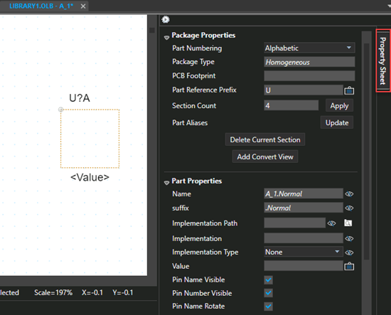
- Choose File – Save.
If you are creating the part in a new library that has not yet been saved, the Save As dialog box appears to name the library file.
- If you edit a library provided by OrCAD X, it is important that you assign a new library name so that your changes are not overwritten when you upgrade or update your software.
- After a part is created, you can add to or decrease the number of parts in the package, even if the part starts out as a package of one.
Ignoring Package Pins
The IGNORE property, available for package pins, provides a method for you to specify that certain pins on a part are ignored when the part is placed on a schematic page. Pins that have the IGNORE property assigned to them do not appear on the schematic page. These pins are not included on the part footprint for any downstream PCB layout tools. Also, note that ignored pins are not included in any back annotation from a layout tool.
- Open a part in part editor.
The part editor is displayed along with the Property Sheet pane.
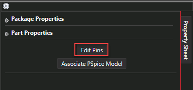
- Click the Edit Pins button.
- In the Edit Pins dialog box, select the Pin Ignore check box for all the pins that you want to ignore.
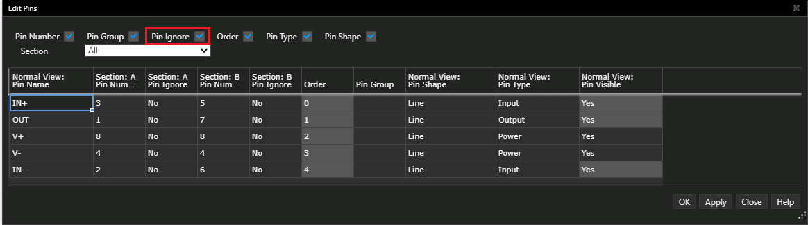
- Click the Apply button.
- Click OK.
- Save the part.
Adding Multiple Parts in Single Package
To add multiple parts into a single package, do the following steps:
- Identify the parts.
- Select one property that the parts share and assign the same value to that property for each part.
You can add a user-defined property to each part. - In the project manager, select schematic folders or schematic pages to process only a portion of the design. To process the entire design, leave the schematic folders or schematic pages unselected.
- Choose Tools – Annotate.
The Annotate dialog box appears. - In the Combined Property String text box, enter the property name. The name must be enclosed in braces: "{" and "}".
- Verify that the remaining dialog box options are set as required.
For example, you can specify whether you are updating all references unconditionally or only those that are set to the unassigned (?) reference. - Click OK.
Shortcut
Toolbar: ![]()
Managing a Package
As with part properties, you can edit package properties in the library or on the schematic page. If you edit package properties on the schematic page, the changes affect only the parts in the project. In effect a new part is created, which is not stored in any library. Package properties are inherited by every part in the package and by every part placed on a schematic page. Packages do not support user-defined properties. You can also delete a part from a heterogeneous package.
Editing a Package
To edit package properties, do the following:
- Select and open a part in the part editor.
The Package Properties section in the Property Sheet pane appears. - Make the required changes in this section and save the part.
You can change the number of parts in the package or the Section Count, PCB Footprint, and Part Reference Prefix. The changes are reflected in the part editor, but they are not committed until you save the part.
To edit pin-specific package properties, do the following:
- Select and open a part in part editor.
- In the Property Sheet pane, make the required changes in the Package Properties section and the Section Pins section.
- Click Apply Pin Changes button.
Capture updates pin property information and checks for duplicate pin numbers.
Editing Part or Net Properties in a Package
Using properties, you can conveniently store part and net information.
- To change part properties on a single part or on every instance of the part in a design, edit the part in the schematic page editor.
- To set part properties on every instance of the part that you place, edit the part in the part editor.
Editing Multiple Part or Net Properties in a Package
You can make changes to a number of parts or nets in the Update Properties dialog box using the using the Tools – Update Properties command. Before you run this command, you need to create an update file where you specify an identifying property or a combination of properties to identify the parts or nets to be updated. For each identifier you use, you must create a separate update file and run the Update Properties command.
To make changes to a number of parts or nets, do the following:
- Choose the Tools – Update Properties menu command.
The Update Properties dialog box is displayed.
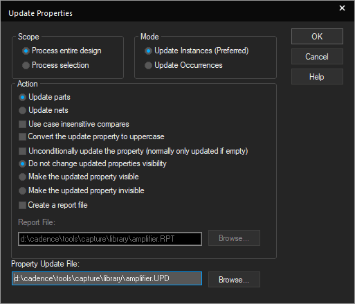
- Select the scope of the updates, whether to process the entire design or a selection.
- Select the mode of updates as required, whether to update the instances or the occurrences.
Capture automatically selects to update either instances or occurrences depending on the type of the design. In general, you should update instances for FPGA and PSpice projects, and update occurrences for PCB and schematic projects.
- Select the required options in the Action section.
You can annotate unconditionally, changing all the parts across all the schematic pages processed.
- Specify the location of the update file.
You can edit any properties except part value, part reference, and netname. - Click OK to commit the changes.
Deleting a Part in a Package
To delete a part in a package of a heterogeneous part, do the following:
- Open part editor for the part package.
- In the Package Properties section of the Property Sheet pane, reduce value of the section count to delete a section.
You cannot undo the deletion of part from a package. Once a section is deleted from a package, all the information regarding the part is lost.
Viewing a Part in a Package
To view a section of a part package, do the following:
- Select the section number from the drop-down list in the lower left corner of the part editor window.
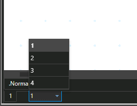
- Choose View – Next Part to switch to the next part in the package. Alternatively, press
CTRL+n. - Choose View – Previous Part to switch to the previous part in the package. Alternatively, press
CTRL+b.
Part Instances and Occurrences
A part instance is a part you have placed on a schematic page. A part occurrence is created each time the part instance occurs in a schematic that is within the design hierarchy. For example, placing a part on a schematic page in your design creates both an instance and an occurrence. You can assign properties to the part instance, in which case the property and its associated value manifests in each part occurrence unless the value is specifically replaced by a value on an individual part occurrence. Property Editor window graphically illustrates the state of instance and occurrence properties.
The instance property values manifest in the occurrence as long as the occurrence property values have not been edited in any way. When you explicitly edit an occurrence property value or when Capture modifies it through one of its tools, the occurrence value overrides the instance value. Only the occurrence value is placed in the netlist.
|
If you... |
The result is... |
|
place a part on an unused page in your design |
only instance properties on that part. |
|
place one part in the root schematic |
one set of instance properties and one set of occurrence properties on that part. |
|
do not modify the occurrence properties on an object |
instance properties manifest in the occurrence. The instance properties may also manifest from the library definition or design cache if the two differ. |
|
edit a part in a library |
no effect on the part in any project. Use the Update Cache command or Replace Cache command to bring library changes into a design. |
How Capture uses Instance and Occurrence Properties
The type of property you update or use in Capture depends on the type of project in which you are working. If you are working with an FPGA project or a PSpice project, Capture defaults to update instances when you use the Annotate, Update Properties, or Export Properties commands. It is recommended to use instances properties to create Cross Reference and Bill of Materials reports, as well.
When you work with a PCB or schematic project, it is recommended to update occurrences when you use the Annotate, Update Properties, and Export Property commands. In these projects, Capture also uses occurrences to create reports with Cross Reference and Bill of Materials.
While modifying occurrence properties, open only one occurrence at a time.
The EDIF 2 0 0, VHDL, and Verilog netlist formats generate true hierarchical netlists. Capture uses the instance property values on nets and parts when it generates a netlist for a design with one of these formats. All other netlist formats in Capture produce flat netlists and use occurrence property values.
Preferred Modes for Design Processing
Capture determines and recommends a preferred mode for processing your design based on the type of project flow, type of design with respect to complex or simple hierarchy, and whether occurrence properties exist on the design.
The Cross Reference Parts dialog box is an example of where you can choose to use instances or use occurrences as the preferred mode.
|
Use instances |
If you are in an FPGA, PSpice, or digital simulation project, or if your design does not have occurrence properties. |
|
Use occurrences |
If your design has at least one schematic used multiple times or a schematic from an external library. Using occurrences is also the preferred mode if the design already has some occurrence properties. |
Removing Part Reference Assignments
To incrementally update a design in which some of the schematic pages have already been updated, you can use the Annotate command to remove part references from those schematic pages.
To remove part references from a design, do the following:
- In the project manager, select schematic folders or schematic pages if you want to process only a portion of the design. To process the entire design, leave the schematic folders or schematic pages unselected.
- Choose Tools – Annotate.
The Annotate dialog box appears.
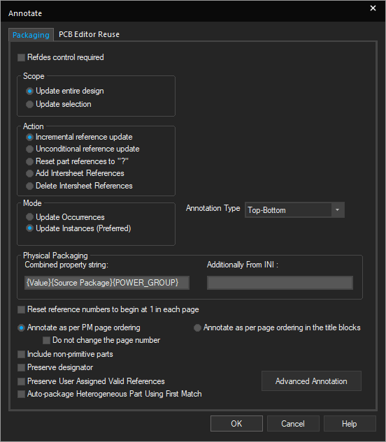
- In the Action group box, select Reset part references to "?".
- Select other options as required.
- Click OK.
Part references are removed from the design.
Shortcut
Toolbar: ![]()
Generating Library Parts
You can generate a part with pins matching all the hierarchical ports on the root schematic of the design for design reuse. If a destination library file does not exist, Capture creates a library part file (.OLB) that contains the newly generated part and a copy of the top-level schematic. The new .OLB appears in the Outputs directory of project manager along with the new part and schematic. The new part has a reference back to the design where the source schematic resides so that when you descend the hierarchy from the placed part, it opens the source schematic from the destination library.
Generate a Part from a PSpice Model Library
To generate a part from a PSpice model library, do the following:
- Choose the Tools – Generate Part menu command.
The Generate Part dialog box is displayed. - In the Netlist/source file text field, enter the path and name of the file you want to use to generate the part, or click the Browse button to browse for it. Ensure that you change the type of files in the Browse File dialog box to PSpice Model Library Files (
*.cir, *.net, *.lib). - Select the Implementation name from the drop-down list box in the Implementation options. If more than one model is available, you can choose one from the drop-down list, or you can keep the default setting of <ALL> that appears in the Implementation name and the Part name text boxes. Choosing <ALL> will create a part from all available models.
- In the Destination part library text field, you can choose to accept the default path and file name, enter the path and name of the file you want to use for the new library, or click the Browse button to search for another one.
- Click OK.
Generating a Part from a Schematic or Library
To generate a part from a schematic design for reuse, do the following:
- In the project manager, select a schematic folder from which you want to create a part. The schematic can be in a design (
.DSN) file or a library (.OLB) file.
The design file you use for the source must contain ports or the Generate Part operation will fail. - Choose the Tools – Generate Part menu command.
The Generate Part dialog box is displayed. Capture fills in the default settings in the Generate Part dialog box. - Browse to change the Netlist/source file or keep the default settings. You can generate a part from an external design or from the current design in the active project manager window.
- Select the Netlist/source file type.
For example, you can select a Capture/Schematic Design to generate a design reuse module. - Keep the default Part name or enter another name from the design.
- If the source design has more than one schematic and no schematic is selected, or if more than one schematic is selected, the Part name setting defaults to the root schematic.
- If the source design is not opened in the current project manager window, its root schematic will be the default Part name.
- Browse to change the Destination part library or keep the default settings. The default setting creates a new
.OLBfile that matches the name of the source .DSNfile. If the source design is a library (.OLB), the default part library name gets the same name as the source file. - Set Primitive property of the new part using the Primitive radio buttons. The default value is No. You can descend from the placed part to its schematic if the Primitive is set to No. For a design reuse module, select Default.
-
Select the Copy schematic to library check box to include a copy of the schematic in the new
.OLBfile along with the new part. This option is unavailable if the source and destination files are the same.If you are generating a design reuse module, do not select the Copy schematic to library option. This can lead to the loss of occurrence properties that are critical in the design reuse module. Also, selecting this option overwrites the custom library. You must specify a used library name unless you intend to overwrite the existing library.
- Click OK.
If the source schematic is copied and is locally available in the library, the implementation path is the same as the destination library. If the source schematic is not copied, the implementation path is the same as the source design or library.
To reuse an existing hierarchical design, do the following:
- Create a new project or open a working design.
- In the project manager, choose the Tools – Generate Part menu command.
- Click the Browse button to select a source design file.
- Select the schematic to reuse.
- Enter a resulting library name or keep the default.
- Select the Copy Schematic to Library check box and click OK to create a part.
- Select the schematic page editor window to place instances of the part to reuse its schematic design.
- Click OK.
To create a pin on a symbol using Generate Part, the pin must have a pin to port mapping in the pin file.
Managing Split Parts
You can split or divide a part into multiple sections, using the Split Part Section Input Spreadsheet.
Creating a Split Part
To split a part into multiple sections, do the following:
- Select the part that you want to split from the Library folder in the project manager.
You need to select a single-sectioned part from a library. You can split a multi-sectioned part only when it has already been split using the Split Part Section Input Spreadsheet. -
Choose the Tools – Split Part menu command. Alternatively, right-click the selection and choose Split Part.
The Split Part Section Input Spreadsheet appears displaying all the pins and their corresponding properties for the selected part. You can resize the window by dragging the borders as required.To sort on any property, double-click its name in the column header.
The Part Name and Part Ref Prefix fields display the name of the selected part and its part reference. These fields are view-only.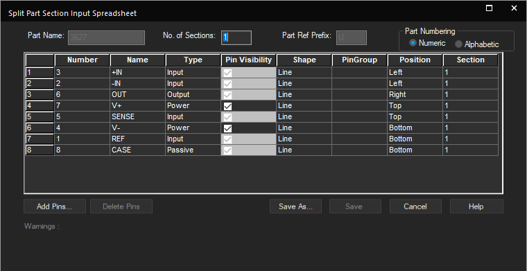
- Select Numeric or Alphabetic in the Part Numbering group.
-- Alphabetic: A letter between A and Z is added as a suffix to the current part reference for each of the split parts. With this selection, you can create up to a maximum of 26 sections.
-- Numeric: A number between 1 and 1024 is added as a suffix to the current part reference for each of the split parts. With this selection, you can create up to a maximum of 1024 sections.
The Section property column changes based on your selection in the Part Numbering group. For example, if Alphabetic is selected, the Section property column displays “A”. - Specify the number of sections you want to have in the split part in the No. of Sections text box.
Number of sections cannot be less than one. The Section property column changes to a list box displaying the number of sections you specified in the No. of Sections text box. -
Click a cell in the Section column for a specific pin and select a section number from the list box.
The selected cell displays the new section number. The pins will be added in the same order in the split part as the order in which the pins appear in the spreadsheet. -
Click the Save button to save the changes to the current part. If any warnings are generated during the save operation, a message box appears prompting you to view the warnings.
-
To view the warnings, click the View Warnings button.
The Split Part Section Input Spreadsheet expands and displays a grid showing warnings messages. -
If you select the Continue button, the split part is saved as is.
-
- Click the Hide Warnings button to hide the warning messages or the Show Warnings button to display the warning messages again.
- Use Save As to retain the original part and save the changed part as a new part in the same library.
You can hide or show a property column in the Split Part Section Input Spreadsheet. To do this, right-click the property column header you want to hide and select Hide from the pop-up menu. The selected property column will not appear now. To show a property column, right-click the property column header next on the right-hand side of the hidden property column and select Unhide from the pop-up menu. The hidden property column appears in the Split Part Section Input Spreadsheet. Alternatively, you can show a property column by:
- Double-clicking the column handle (
 ) of the property column header.
 - Dragging the column handle of the property column header.
- (only the last two methods can be used to show a property column, which is the last column in the Split Part Section Input Spreadsheet).
If the number of Sections specified in the Split Part Section Input Spreadsheet is greater than one, then the resulting part will be of heterogeneous package type.
You can change the order in which the property columns and rows appear in the Split Part Section Input Spreadsheet. To do this, select the property column/row header you want to move and drag and drop it to the location where you want it in the Split Part Section Input Spreadsheet.
You can use standard copy and paste features to copy all the data from the Split Part Section Input Spreadsheet to MS Excel. You can later use the MS Excel file for archiving or documentation. It is recommended that you avoid using MS Excel to paste information into the Split Part Section Input Spreadsheet.
Adding pins to Split Part Section Input Spreadsheet
You can add more pins to the Split Part Section Input Spreadsheet. The pins are added at the end of the current set of pins. The pins numbers for the added pins is generated automatically.
To add a pin
- From the Split Part Section Input Spreadsheet, Click the Add Pins button. The Add Pins dialog box appears.
- Specify the number of pins you want to add in the Number of Pins text box.
- Click OK. The required pins are added at the end of the current pin set in the Split Part Section Input Spreadsheet.
All the pins added are populated with default property values. The default value for the Section property column is one.
Deleting pins from Split Part Section Input Spreadsheet
You can delete pins along with their corresponding properties in the Split Part Section Input Spreadsheet.
To delete a pin
- Select a row in the Split Part Section Input Spreadsheet.
- Click the Delete Pins button. A message box appears asking you to confirm the deletion.
- Click OK to confirm deletion. The selected row containing the pin information is deleted from the Split Part Section Input Spreadsheet.
Once you delete a pin from the Split Part Section Input Spreadsheet, you cannot retrieve it later.
Viewing Split Part Properties
When you split a part, Capture assigns the following properties to it:
- SWAP_INFO—This property is assigned to each section and its value is determined by the number of sections you specified in the No. of Sections text field in the Split Part Input Spreadsheet. For example, if you split a part into 3 sections then all the 3 sections will be assigned the SWAP_INFO property with value (S1+S2+S3).
- SPLIT_INST=TRUE
Ensure that you use ‘(‘ and ‘)’ brackets for defining single sections. For example, If you have a split part having 6 sections (S1 to S6) and wish to add the SWAP_INFO property such that swapping happens only between sections S5 and S6, you need to add the SWAP_INFO value as (S1), (S2), (S3), (S4), (S5+S6).
Saving a multi-section split part will remove any existing SPLIT property. Instead, it will add the SPLIT_INST property.
Saving a multi-section split part will overwrite any existing SWAP_INFO property value with the value (S1+S2+S3+...Sn), where n is the number of sections specified.
To view split part properties, do the following:
- Double-click a split part from the Library folder in the Project manager. The Part editor window displays.
-
Select the Options menu and choose Part Properties. The User Properties dialog box is displayed. The following figure shows a split part with the two properties assigned to it.

The SWAP_INFO and SPLIT_INST properties appear in the User Properties dialog box for only those parts that are heterogeneous.
Viewing split part package and its properties
A split part is a multi-sectioned package. You can view a split part in package view.
To view split part package, do the following:
- From the part editor, select the View menu and choose the Package command. An image of all the sections in the package appears.
OR - You can also double-click a split part from the Library folder in the project manager to open the part editor window.
The part reference for each of the sections contain a suffix entry. For example, J?A, J?B, and J?C, where A, B, C are the section numbers.
To view split part package properties, do the following:
- From the part editor, select the View menu and choose the Package command.
- Select the Options menu and choose the Package Properties command.
The Edit Part Properties dialog box displays.
The Multi-Part Package group displays the properties for your split part package, like parts per package, package type, and part numbering.
Deleting a Part
To delete a part
- Open the library containing the part to delete.
- In the project manager, select the part.
- Right-click the part and choose Delete.
- To save the changes to the library, choose Save from the File menu.
Creating Components
You can create components in the local library workspace using existing symbols, models, footprints properties. You can add existing CAD models of the following types into the workspace at %HOME%\workspace\ and build parts using the models in the Cloud workspace:
- Symbols – (.
olb) - Footprints – (
.dra, .psm, .pad) - PSpice models – (
.lib) - 3D – (.
stp) - Technology file –
techfile
To create a new component, follow these steps:
- Choose the Place – Component menu command.
- In Component Explorer, right-click the My Workspace node in the Categories pane and choose New Component.
Alternatively, use one of the following ways to create a new component: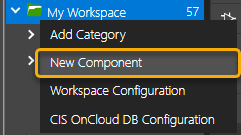
-- Click the New Component button in the Component Explorer interface.
-- In the project manager:
1. Open a new.olbfile.
2. Select the Library node in the project manager tree.
3. Right-click a library name and choose New Component.
The Component dialog box is displayed providing you an interface to create a new component using existing symbols and footprint information.
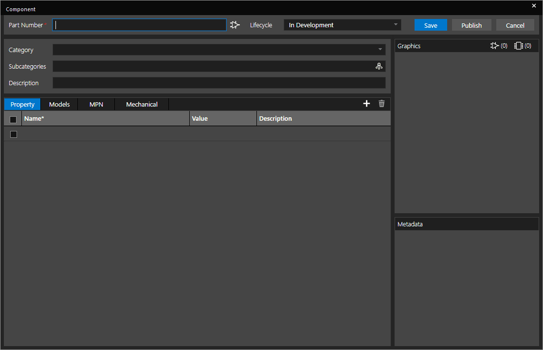
- Specify a part number in the Part Number field.
The image next to the Part Number field indicates the type of the part. You can create the following types of components:
- Electrical
- Mechanical
The type is determined by the seeded category. The default category is Electrical. To create a Mechanical component, you first need to create a category of the type and then create the component. -
Select the lifecycle status of the component from the Lifecycle field.
This field helps in understanding the availability status of a component: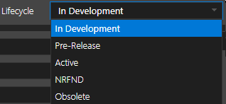
Lifecycle Stage Component Availability Status In Development The component is being developed. Pre-Release The component is developed but not released yet. Active The component is actively available for use in the designs NRFND The component is Not Recommended for New Designs. Obsolete The component is no longer available for use. You can create a component from scratch or use an existing category.
- Optionally, select a category from the Category list.
You can choose an existing category from the Category list to use as a template to create the component. When you select a category, the symbol, footprint, description, and part-level properties are automatically assigned to the component as illustrated in the following image:
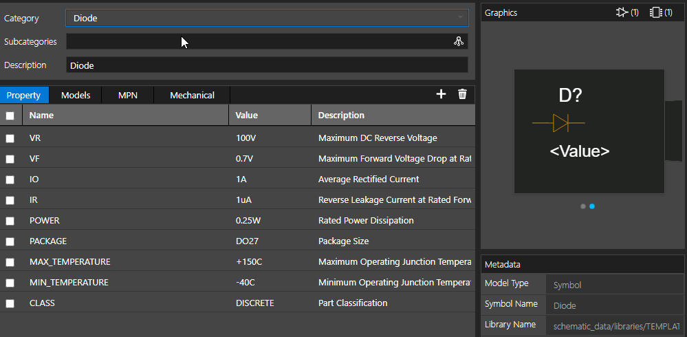
- Specify a brief description of the component or update the entry if you selected a category.
- In the Property tab, click the Add icon (plus sign) to add a new property. You can add more properties by clicking the plus sign.
-
Specify a property name, value, and description for the property.
Alternatively, you can copy data from Excel-like grids into the Property or MPN grid in the Category or Component dialog boxes as illustrated in the following example:
-- Copy the rows in the following table:Property Name Value RDSON 19.2mVDS 20ID 10PD 2.5VGS 1.45
-- Now, click an empty row in the Property grid and press CTRL+v. The data is copied as new property rows: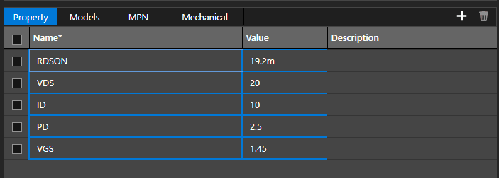
To remove a property from the component, select the check box to the left of the property name, and click the Delete icon.
-
Click the Models tab.
You can add a symbol, a PSpice model, and a footprint to the component in the Models tab. -
Click the Attach icon and choose Symbol.
The Symbols dialog box displays a list of symbols from the available libraries.
For the components based on a category, symbols and footprint are pre-selected. You can select any other symbol or footprint from the list of available symbols and footprints. - To search for symbols across libraries, specify a search string in the Search bar and click the magnifying glass icon or press
Enter.
The string is searched in both the library list and the symbol list sections. The symbol library list displays the library files that include the string and the symbol list displays all the symbols in the selected library containing the string.
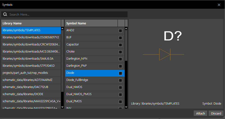
- To associate a symbol with the component, select the check box next to the symbol.
The name of the first symbol you select starts appearing in bold and is set as primary. This indicates that the selected symbol is set as the primary symbol for the component. You can change this by selecting another symbol and choosing Set as Primary from the shortcut menu on the symbol.
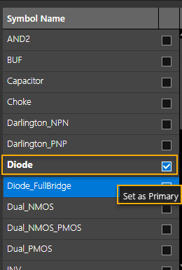
- Click the Attach icon and choose Footprint to associate the footprint information.
The Footprints dialog box displays a list of available footprints for you to choose.
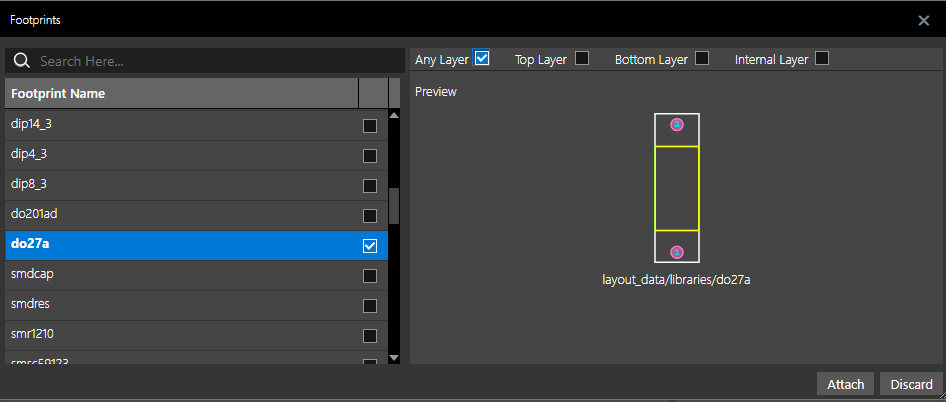
- To associate a footprint with the component, select the check box next to the footprint.
- Choose the layers to which the footprint is to be associated: Any Layer, Top Layer, Bottom Layer, and Internal Layer.
The first footprint you select appears in bold text. It is the default footprint and the
PCB_FOOTPRINTproperty gets assigned to this footprint on symbol. You can also select one or more alternative footprints. These alternative footprints are associated with theALT_SYMBOLSproperty. - Click Attach.
- To associate a PSpice model with the symbol, click the Attach icon and choose PSpice Model.
The Associate PSpice Model dialog box opens. -
Select the PSpice model library containing the model to be associated with the component in the Model Library drop-down list.
All the PSpice model libraries available in the Cloud database can be accessed from the Model Library list. You need to ensure that the required PSpice model library is present at the following location: $HOME\cdssetup\workspace\schematic_data\libraries. You can access Cloud data from the File Manager user interface.You need to add the path to the PSpice models library (
LIBPATH) inpspice.inito run the PSpice simulation. Else, the simulation will fail.LIBPATH=”$HOME\cdssetup\workspace\schematic_data\libraries”The Matching Models section is populated with the list of models that can be associated with the selected component.
The Model Text section displays the model definition of the model selected in the list.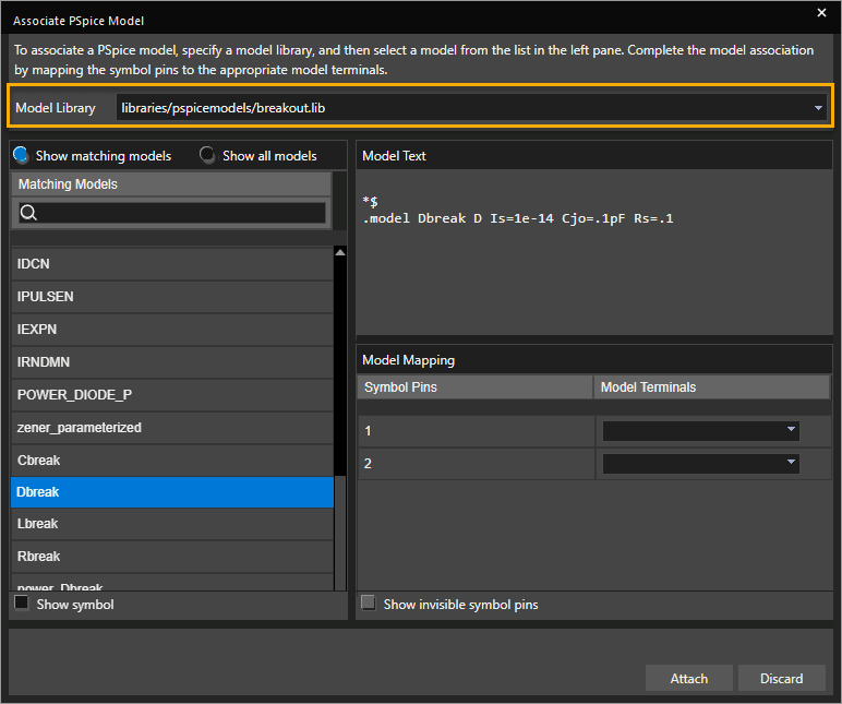
- Select the required model from the list or search for a specific model.
- In the Model Mapping section, map the symbol pins to the correct model terminal. For this, select a port from the Model Terminals for each symbol pin.
- Click Attach.
The associated symbol, footprint, alternative footprint, and the PSpice model display in the Models tab.
Associated symbol and footprint graphics and the metadata for the selected symbol and footprint also display in the right pane: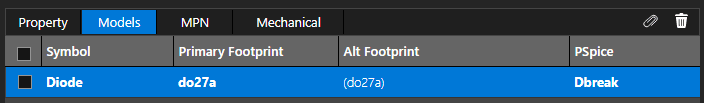
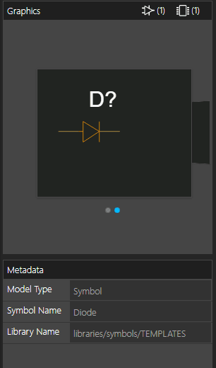
- Click the MPN tab.
- Click the Add icon to add a Manufacturer Part Number (MPN) to the component.
- Specify required values for the MPN, manufacturer name, datasheet URL, and RoHS (Restriction of Hazardous Substances) compliance.
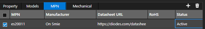
- Click the Mechanical tab and then click the plus sign to add a Mechanical part.
The Add Mechanical Part dialog box opens. A list of available mechanical parts is displayed if the mechanical parts exist in the workspace.
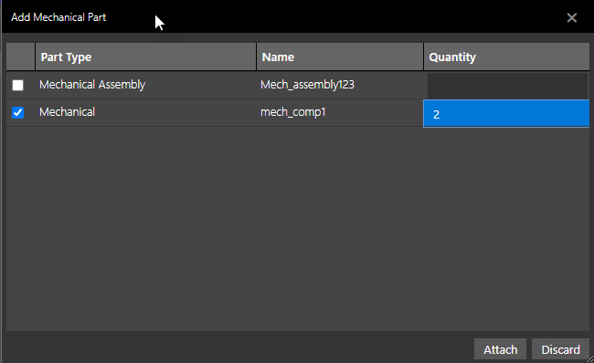
- Select the check box to the left of Mechanical Assembly or Mechanical part types.
- Specify the quantity of the mechanical parts to be included in the assembly.
- Click Attach.
The selected part is added in the Mechanical tab.
When you have added all the details to the component, you can choose one of the following actions:
-- Publish - Saves the component and publishes it to a shared workspace, simultaneously. When you click the Publish button to publish the component, first it is saved and then the Publish dialog box is displayed, where you select the shared workspace to publish the component.
-- Save - Saves the component to My Workspace. - Click Save.
The component appears in the list of available components in My Workspace. Note that the component properties display in the properties browser on the right and the associated symbol and footprint appear in the Symbols and Footprints section.
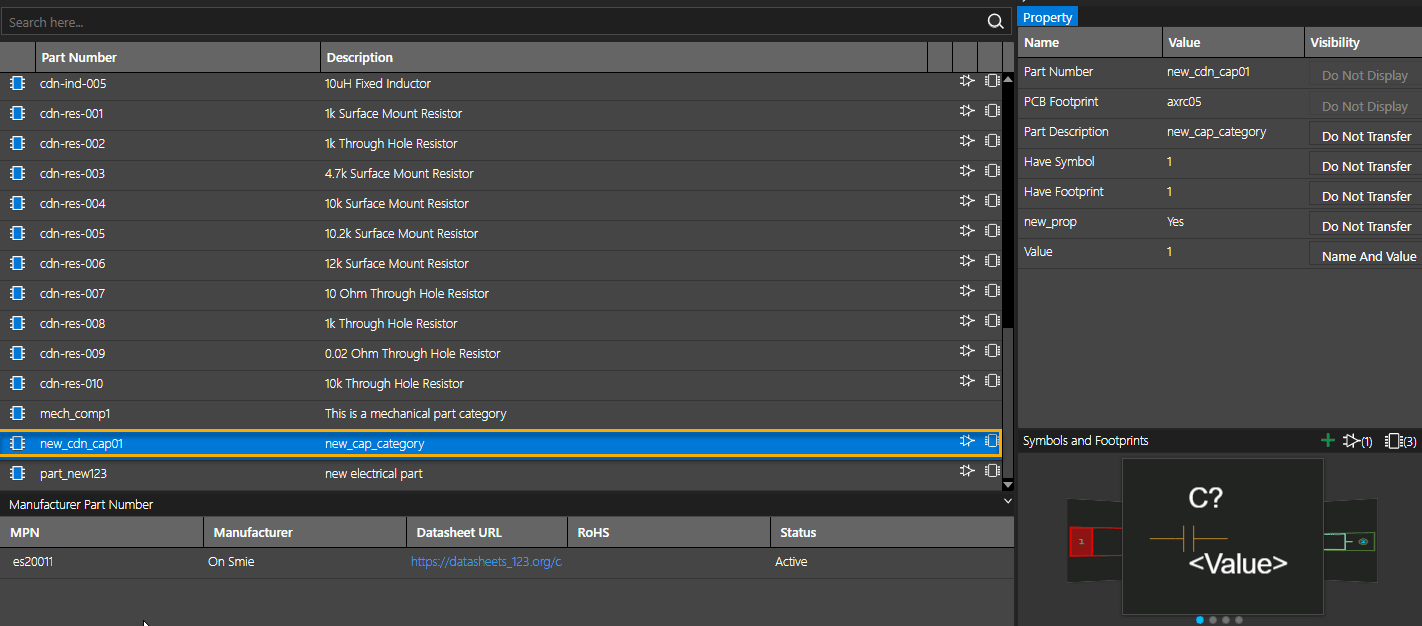
Annotating Properties on Schematic
Component property annotation and visibility are set to default values defined in the category on which the component is based. For a component created from scratch, the default value of properties is set to Do Not Transfer. You can override this behavior by changing the value of the Visibility column for a property in the property browser of the Component Explorer interface.
To annotate a property on schematic canvas with visibility settings different from those defined in the category, do the following:
- In the property browser (the right pane) of the Component Explorer interface, click the Visibility column for a property.
- Select one of the available options to change the visibility of the property:
When you place this component on the schematic, the properties display as selected in the Visibility column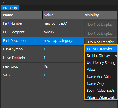
Sharing Components
You can publish a component in your local workspace to create its copy in the shared workspace. All the team members with access to this workspace can work on the component.
To share a copy of a component in your local workspace, do the following:
- Right-click the component to be shared and choose Publish. Alternatively, click the Publish button in the Component dialog box.
-
In the resultant Publish Part dialog box, select the target workspace where the components are to be published for sharing.
Note that My Workspace is selected by default in the Source Workspace field. The component and any MPN associated with the component is also listed. The Action column lists the most recent action done on the object since the last time it was published. ADDED indicates the component is being published for the first time. Similarly, UPDATED and DELETED indicate if a component was updated or deleted since the last time it was published. -
Select Minor, Major, or Custom depending on how you want to save the version.
By default, the published part is saved with a Minor version.If ASME revision standard is enabled in the Extended Preferences dialog box, the revision pattern switches from numeric to alphabetic, and and the standard delimiter (.) is replaced by the selected ASME delimiter.
- If you select Custom, specify a revision value.
- Select the object to be checked out.
- Select Delete from My Workspace, if you want to delete the component from the local workspace.
- Click Publish.
- Click the shared workspace in the Categories pane.
The published component appears in the shared workspace.
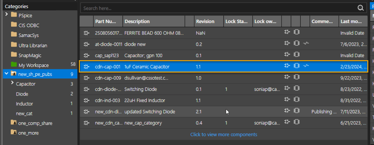
Component Locking
When a component is checked out, it is locked by the current user (lock owner). The Lock Status and Lock Owner columns are updated to reflect the status. This component will be available for editing by other users only after the lock owner checks it back into the shared workspace by publishing it or unlocks the file explicitly using the Unlock command. Any user trying to edit a component locked by another user is notified of the status.
When publishing a component from a source shared workspace to a target shared workspace, it is checked whether the component is locked in the destination workspace. The check is not done on lock status of the component in the source workspace. This is done because the components in the two shared workspaces are independent of each other. A component can be published to a shared workspaces and then copied to My workspace for editing. From My Workspace, the component can be published back into the shared workspace.
As the components in the two shared workspaces are independent of each other, they can have the same revision, but different content.
Editing Shared Components
All the members with access to this shared workspace, can use this component depending on the assigned roles. To edit a shared component, it needs to be moved to the local workspaces (My Workspace).
To edit the component, do the following:
- Right-click the component and choose Edit.
The component will be published to My Workspace for editing - Click OK.
The Lock Status and Lock owner columns are updated to reflect the status of the component.
The component is copied to the local workspace where you can edit it.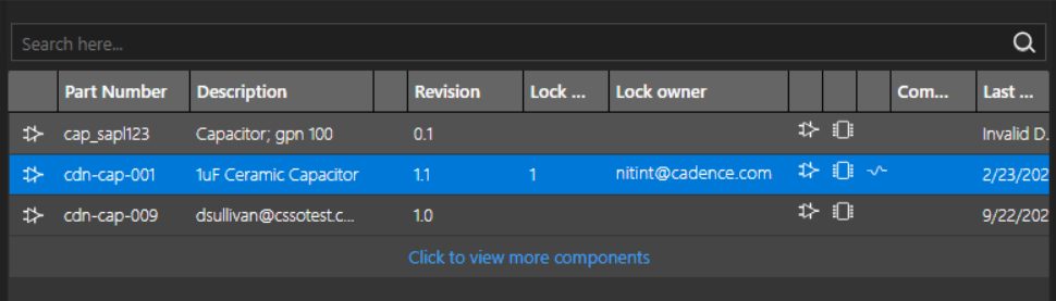
After making the required changes to the component, you need to check it back in to the shared workspace. - Right-click the component in My Workspace and choose Publish.
- Select the Minor, Major, or Custom revision options as required and add any tags or comments.
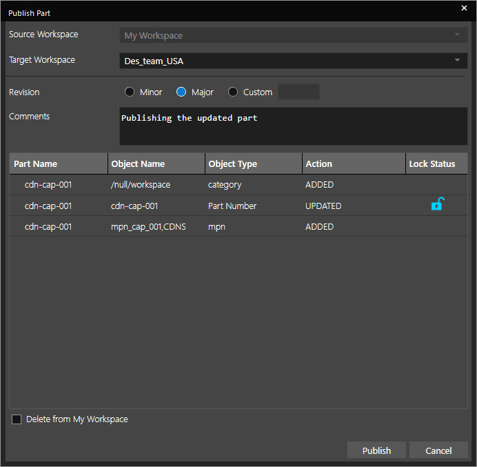
- Click Publish..
If the regions of the destination workspace and the source workspace do not match, the following message is flagged:
- Click Yes.
The component is updated in the shared workspace. The version number of the component is modified as specified and it is unlocked as well.

The History tab lists the previous version of the component. Each time this component is modified and checked in, a new row is added for the previous version. You can restore or roll back to a previous version of the component using the Edit command from the shortcut menu. You can also copy a read-only version to the local workspace or delete it from the workspace.
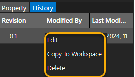
Managing Categories
A category is a template that simplifies and speeds up the creation of components. You can create a category with pre-defined symbols, footprints, and properties, and then create components based on the category. A category not only helps in categorizing parts in the category tree, but also acts as a template at the time of creating a new component.
Adding a New Category
To create a new category, follow these steps:
- Right-click My Workspace and choose Add Category.
The Category dialog box opens. This is where you create a new category. Note that the properties from the CIS database are included by default.
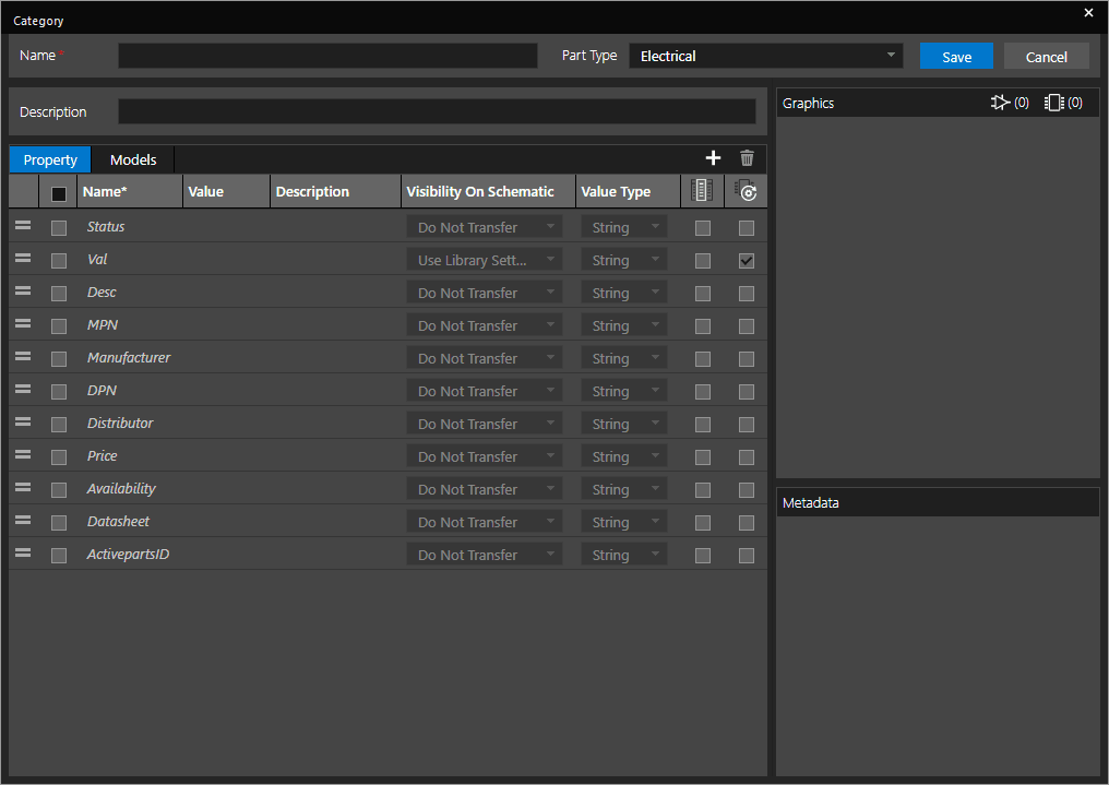
- Specify a name and description for the new category.
- Select a part type from the Part Type List. The default part type, Electrical, is pre-selected.
You can choose from the following options:
- Electrical
- Mechanical - In the Property tab, click the Add icon (plus sign) to add a new property to a category.
Any component created based on this category inherits the properties defined for the category.
A blank row is added for a new property where you specify the property details
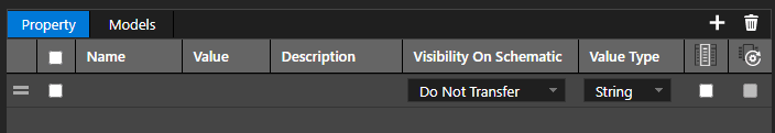
- Specify a name, value, and description of the property. Alternatively, copy data from Excel-like grids into the Property grid.
A category controls how a property is transferred to the schematic. You can specify the default behavior of property transfer while defining the category in the Visibility On Schematic column.
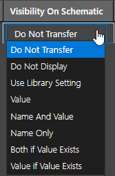
The following table provides a description of the options the Visibility On Schematic column provides:
Option Description Do Not Transfer The property is not annotated to the schematic design. Do Not Display The name or the value of the annotated property is not displayed on the schematic canvas. Use Library Setting With this option selected, the property is annotated to the schematic design. If the same property is also defined at the library level, its visibility is set by the display option set in the library. Value The value of the annotated property is displayed on the schematic canvas. Name and Value The name and value of the annotated property is displayed on the schematic canvas. Name Only Only the name of the annotated property is displayed on the schematic canvas. Both if Value Exists Both the name and the value of the annotated property are displayed on the schematic canvas, if the value exists. Value if Value Exists The value of the annotated property is displayed on the schematic canvas, if it exists. - To display this column alongside the component in the part browser after a component is placed, select the checkbox in the Show in Place Component field.
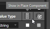
- Select the checkbox in the Update Part Property field to update the part property with this property when you choose the Link Database Component menu command or click the Update button in the View Database dialog box,.
- Click the Models tab to associate symbol, footprints, and PSpice models with the category.
For details see, Creating Components. - Click Save.
The category is displayed under the My Workspace node.
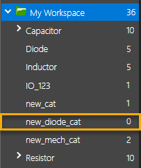
The numeral next to the category indicates the number of components created using this category.
Adding Subcategories
Subcategories further help you organize the categories into logical groups for easier identification.
To create a subcategory, do the following:
- Right-click the category under the My Workspace node and choose Add.
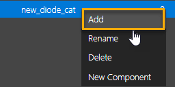
- Specify a name for the subcategory and press ENTER.
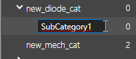
The subcategory is created. You can create multiple levels of subcategories within a subcategory.
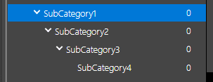
Modifying a Category
You can edit, duplicate, or delete an existing category.
You can modify a category in the following ways:
- Right-click the category under the My Workspace node and choose the desired option from the following list:
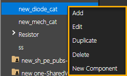
- To edit a category, choose Edit.
The Category dialog box opens where you can change the category details. - To create a copy of the category, choose Duplicate.
The Category dialog box opens where you can specify a new name for the category and save it as a new category. - To delete a category, choose Delete.
The selected category is deleted. - To create a new component based on the category, click New Component.
The Component dialog box opens with pre-seeded values from the category. You can specify a part number for this component and save it.
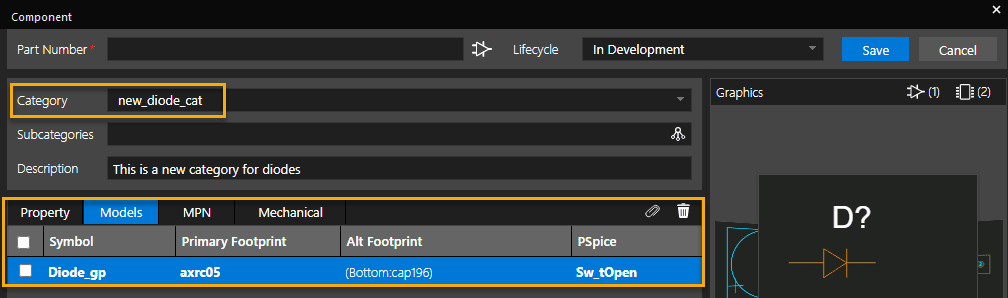
Managing Mechanical Assemblies
In addition to electrical components, some non-electrical components on a PCB are used for mechanical support, such as screws and connectors. You can create categories or templates for mechanical assemblies and parts and then associate them with electrical components.
Creating a Mechanical Category
To create a mechanical category, do the following:
- In Component Explorer, right-click the My Workspace node and choose Add.
- In the Part Type field, select Mechanical.
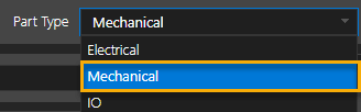
- Specify details, such as name and description.
- Associate mechanical symbols and footprints from the available libraries. See Managing Categories.
Note that the PSpice Model option is deactivated for a mechanical symbol.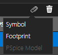
- Click Save.
The new mechanical category is created.
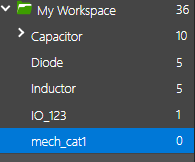
Creating a New Mechanical Part
To create a new mechanical part, do the following:
- Right-click the mechanical category and choose New Component.
The Component dialog box opens. Note the icon next to the Part Number field. It indicates that the component type is mechanical.

- Specify the details to create the component. See Creating Components for details.
- Click Save.
Creating a New Mechanical Assembly
To create a new mechanical assembly, do the following:
- Right-click the mechanical category, choose New Mechanical Assembly to create a new mechanical assembly.
The Component dialog box appears where you specify the required details.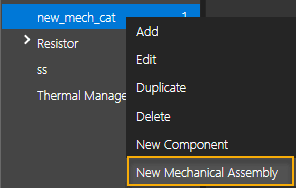
- Click the Mechanical tab.
- Click the Add (plus) icon.
The Add Mechanical Part dialog box opens. A list of available mechanical parts is displayed.
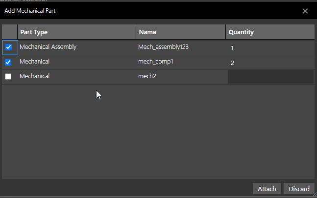
- Select the check box to the left of Mechanical Assembly or Mechanical.
- Specify the quantity of the mechanical parts to be included in the assembly.
- Click Attach.
Selected part added in the Mechanical tab. - Click Save.
Configuring CIS OnCloud Database
To reuse an existing CIS database in the OnCloud environment, you configure the CIS OnCloud database. You can also import a CIS Database Configuration file (.dbc) to any workspace. After the database configuration file is imported, any new category you create is pre-seeded with the common database properties.
To configure the CIS OnCloud database, do the following:
- In Component Explorer, right-click a workspace node and choose CIS OnCloud DB Configuration.
The common properties in the CIS part database are listed in the CIS OnCloud DB Configuration dialog box. The database property names are mapped and displayed along side the corresponding schematic property names.
Note that the database properties, PART_NUMBER, PCB_FOOTPRINT and PSPICE_MODEL appear italicized, indicating that they cannot be edited, while the editable schematic property names appear in bold.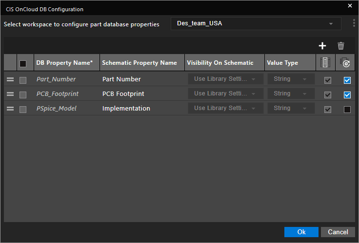
You can select the workspace to configure the part database properties. Database properties can be configured for each workspace, separately. The workspace from where you launch this dialog box is pre-seeded. - Edit the schematic property names, as required.
The property names on the schematic of these properties can be changed as illustrated in the following example:
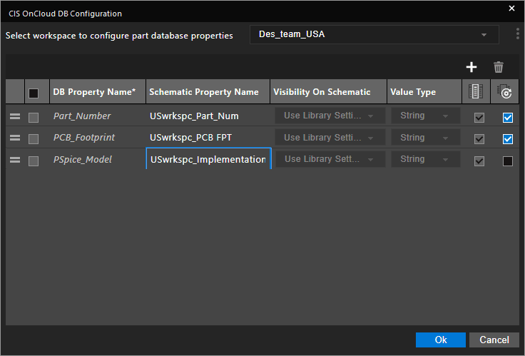
- Click Ok.
The updated property names are reflected in the part and property browser in Component Explorer.

Importing from DBC
To use an existing CIS DBC settings in the OnCloud environment, do the following:
- In Component Explorer, right-click a workspace node and choose CIS OnCloud DB Configuration. For example, right-click My Workspace.
The CIS OnCloud DB Configuration dialog box is displayed.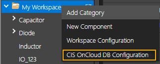

- Select the workspace to configure the part database properties.
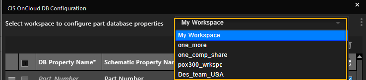
- Click the hamburger menu (vertical ellipsis icon) on the top-right of the window.
The Import from DBC button pops up.
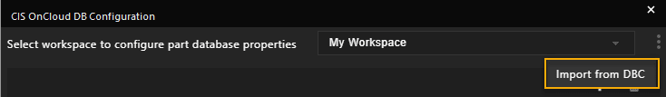
- Click the Import from DBC button.
All the common CIS database properties are imported to the OnCloud workspace.
You can edit the property names, their values types, and visibility on the schematic as illustrated in the following image: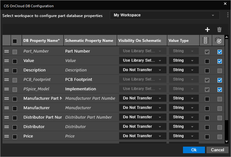
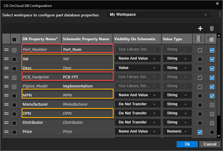
If DB Configuration from which properties are imported doesn't have the PSpice_Model property configured, the default database property, PSpice_Model gets deleted in the CIS OnCloud DB Configuration dialog box.
You can even add a new database property.
- Click the Add (+) button.
- Add a property name in the new row, and specify the value type and visibility of the property.
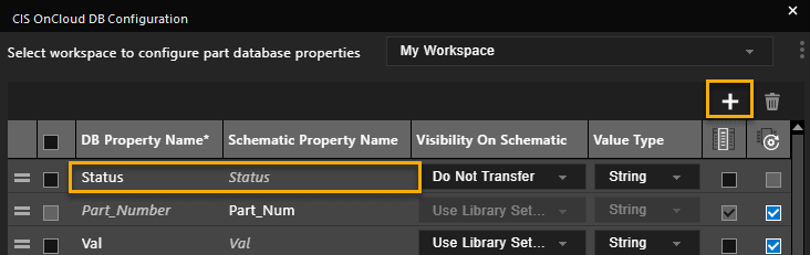
- Click Ok to commit the changes.
When you create a new category after importing the DBC, all the imported properties and the new properties you added are pre-seeded in the category definition.
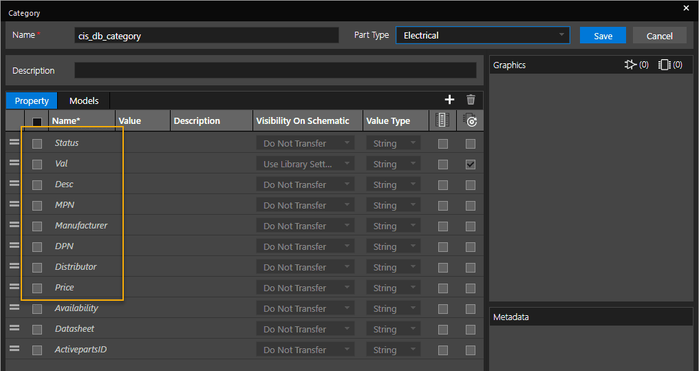
If you have any questions or comments about the OrCAD X platform, click on the link below.
Contact Us