How to Do Transient Analysis in PSPICE
Key Takeaways
- PSpice transient analysis lets you simulate circuits' time-dependent behavior, which is ideal for observing startup, switching, or oscillation dynamics.
- With OrCAD X and PSpice, setup is simple: define a simulation profile, configure time-domain parameters, and visualize results with probes.
- The Checkpoint Restart feature speeds testing by letting you resume simulations from saved points—perfect for tuning components post-startup.

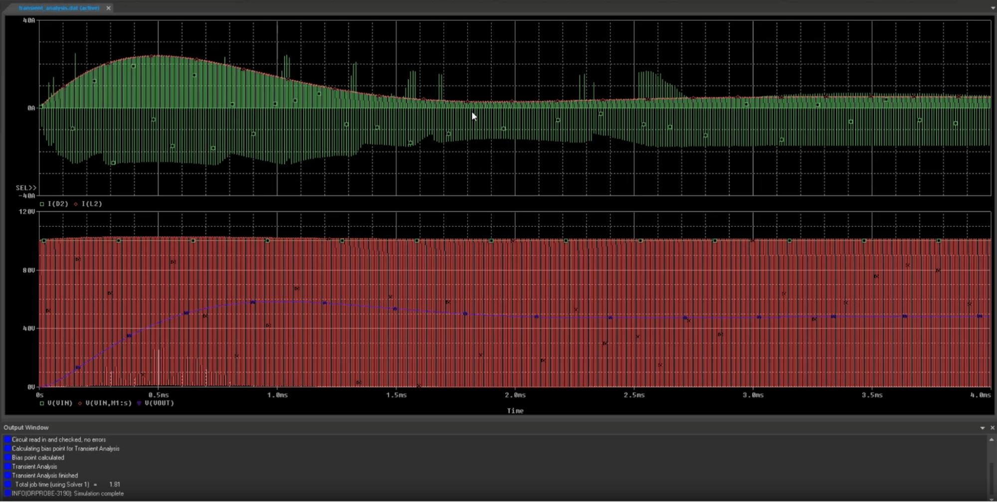
Transient Analysis of a buck converter circuit in OrCAD X
Understanding how a circuit behaves over time, especially when subjected to changing inputs or switching events, is crucial for verifying its functionality and stability. These conditions are where transient analysis becomes an indispensable simulation tool. PSpice, integrated within the OrCAD X environment, allows engineers to perform detailed time-domain simulations, which calculate circuit responses—such as -voltages and currents—as they vary continuously over time due to dynamic or non-steady-state conditions. This guide will walk you through how to do transient analysis in PSpice, from setting up your circuit to interpreting the results.
Why Perform Transient Analysis?
|
Aspect |
Description |
Example Use Case |
|---|---|---|
|
Time-Domain Response |
Evaluates how circuits respond to time-varying inputs like steps, pulses, or sine waves. |
Analyzing the output waveform of a low-pass RC filter with a pulse input. |
|
Startup Behavior |
Shows how voltages and currents evolve when the circuit is first powered on. |
Observing how a power supply ramps up voltage when first turned on. |
|
Switching Characteristics |
Analyzes the behavior of switches and transistors (e.g., in DC-DC converters or digital circuits). |
Checking voltage spikes and switch timing in a buck converter. |
|
Oscillations & Stability |
Helps detect undesired oscillations and assess damping in resonant circuits (like RLC networks). |
Investigating ringing in an LC tank circuit or amplifier feedback loop. |
|
Timing Parameters |
Measures rise/fall times, delays, and pulse widths critical in digital and analog design. |
Verifying timing constraints in a logic gate or clock pulse chain. |
Setting Up for Transient Analysis in OrCAD X
Set up your OrCAD X environment and schematic before learning to do transient analysis in PSpice.
- PSpice-Enabled Project:
- When creating a new project (File > New > Project), make sure the "Enable PSpice Simulation" checkbox is selected. This selection activates the PSpice menus and toolbars necessary for simulation.
- If opening an existing project, confirm if PSpice is enabled.
- Transient analysis requires a time-varying input source to observe a dynamic response. Common PSpice sources for this include:
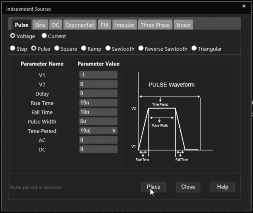
- Pulse: For generating square waves, pulses, or step functions. You'll define parameters like initial voltage (V1), pulsed voltage (V2), time delay (TD), rise time (TR), fall time (TF), pulse width (PW), and time period (PER).
- Sine: For sinusoidal inputs, defining offset, amplitude, frequency, and phase.
- PWL Sources: For creating arbitrary piecewise linear waveforms defined by time-voltage/current pairs.
- Place these sources using Place > PSpice Component > Source or via the Modeling Applications (Place > PSpice Part > Modeling Application), which provides a guided interface for setting source parameters.
- You might replace a DC source with a VPULSE source for an RC circuit to observe the capacitor charging and discharging.

The Modelling Application allows you to create many voltage sources with simple inputs
Getting Started with Transient Analysis in PSpice
|
Step |
Action |
Details / Description |
Notes / Tips |
|---|---|---|---|
|
1 |
Create a New Simulation Profile |
In OrCAD X Capture go to PSpice > New Simulation Profile. Name it (e.g., Transient_Pulse_Response), then click Create |
Use descriptive names for clarity and project tracking |
|
2 |
Configure Transient Analysis Settings |
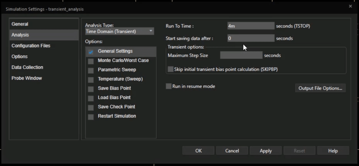
The Simulation Settings dialog opens automatically |
Located under Analysis type: Time Domain (Transient) |
|
Set Run to Time |
Total duration for simulation (e.g., 5ms, 100µs) |
Ensure it's long enough to capture full circuit behavior |
|
|
Start Saving Data After |
Set to 0 to record from the beginning or specify a delay (e.g., 1ms) to skip transient startup |
Useful for focusing on steady-state behavior |
|
|
Maximum Step Size (Optional) |
Leave blank for automatic adjustment or enter a value for higher resolution (e.g., 10ns) |
Helps with fast signal transitions or noise smoothing |
|
|
Save Settings |
Click Apply, then OK |
The simulation profile is now ready |
|
|
3 |
Place Voltage/Current Probes (Markers) |
Use toolbar icons or PSpice > Markers |
Required to visualize data post-simulation |
|
Voltage Probes |
Place on the nets or component pins |
Measures voltage relative to ground |
|
|
Current Probes |
Place directly on component pins |
Measures current into/out of a device |

Transient Analysis Simulation Settings
How to Do Transient Analysis in PSpice
|
Step |
Action |
Details / Description |
Notes / Tips |
|---|---|---|---|
|
4 |
Run the Simulation |
Click the green Run PSpice icon or go to PSpice > Run |
Starts the transient simulation using your profile |
|
5 |
Analyze Results in Waveform Viewer |
Opens automatically when the simulation completes |
Visualizes voltage and current waveforms |
|
Reading Waveforms |
X-axis: time, Y-axis: voltage or current; traces are color-coded |
Matching trace names with probes simplifies analysis |
|
|
Add Plots & Traces |
Creates new Y-axis plots: Plot > Add Plot to Window, then add new markers Select node voltages, device currents, or expressions: Trace > Add Trace |
Use separate plots for voltage and current for clarity |
|
|
Add Cursors for Measurement |
Enables cursors: Trace > Cursor > Display |
Track voltage/current levels at specific times, measure time differences, peak values, and rise/fall times |
|
|
Save Plot Configurations |
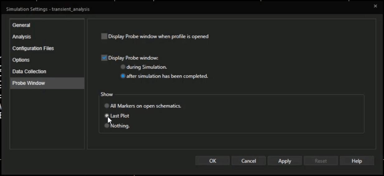
Probe Window Settings > Last Plot |
Reuse display settings across runs or for documentation |

Reuse Plot Setup with "Last Plot" in the Probe Window
Advanced Transient Analysis Feature: Checkpoint Restart
PSpice Checkpoint Restart feature allows you to save the simulation state at defined intervals during a transient run and restart from any of these points later, even after modifying component values. This feature significantly reduces simulation time, especially for circuits with long startup transients or when validating steady-state behavior after small design changes. It's ideal for improving efficiency during iterative design and analysis workflows.
How to Use Checkpoint Restart
- Enable Save Checkpoint: In the Simulation Settings (Transient analysis), check the "Save Checkpoint" option. Specify the file path for saving checkpoints and the "Simulation interval" at which states should be stored (e.g., every 1ms).
- Run Initial Simulation: PSpice will save checkpoints at the specified intervals.
- Restart from Checkpoint: To restart, go back to Simulation Settings. Deselect "Save Checkpoint" and select "Restart simulation." Choose the desired simulation time (e.g., 3ms) from the dropdown menu of saved checkpoints.
- Re-run: The simulation will start much faster, beginning from the selected checkpoint time.

Restart your simulation checkpoint at any time.
Any circuit designer must know how to do transient analysis in PSpice. Whether you're analyzing the response of a simple RC filter, the switching characteristics of a buck converter, or the stability of an amplifier, transient analysis in PSpice provides the flexibility to virtually test and validate various designs before hardware development, saving time, money, and materials in the long run.
Ready to explore the dynamic world of your circuits? Try OrCAD X for free, which includes PSpice, or explore the complete OrCAD X platform to unlock even more advanced simulation and analysis capabilities.
Leading electronics providers rely on Cadence products to optimize power, space, and energy needs for a wide variety of market applications. To learn more about our innovative solutions, subscribe to our newsletter or our YouTube channel.