Aerospace PCB Design Standards with Allegro X
Key Takeaways
- IPC-6012DS and AS/EN 9100 are essential for ensuring the high reliability and performance of aerospace PCBs under extreme conditions.
- AS9100 and IPC Class 3A standards enforce stringent quality management, risk management, and performance requirements.
- Allegro X System Capture's electrical stress analysis aids in early identification and correction of potential failures, enhancing PCB reliability.
Aerospace PCB design standards ensure that jets, satellites, planes, and more are reliable and failure-free.
When designing aerospace PCBs, a precise understanding of PCB design and manufacturing is critical to ensure long-term operation under extreme conditions. For this reason, following aerospace PCB design standards is essential.
Ensuring structural strength, corrosion resistance, heat dissipation, and electrical capabilities adhere to a high degree of reliability and robustness without leaving room for error is critical. Aerospace PCB assembly faces significant challenges due to these harsh environmental conditions. This article will explore various aerospace PCB design standards including, guidelines for aerospace PCB design.
Important Aerospace PCB Design Standards
|
Standard |
Description |
|
IPC-6012DS |
An addendum to IPC-6012D for aerospace and military applications, offering enhanced qualification and performance requirements for rigid PCBs. |
|
AS/EN 9100 |
Internationally adopted quality management system standard for the aerospace industry, with additional requirements beyond ISO 9001 for quality and risk management. |
|
AS9100D |
Lists QMS requirements for aerospace industry suppliers. |
|
AS9101E |
Provides guidelines for QMS reporting and auditing. |
|
AS9102B |
Specifies first article inspection (FAI) requirements. |
|
AMS2750E |
Covers pyrometric requirements to ensure adherence to heat treatment specifications for instruments, thermal processing equipment, and sensors. |
|
AS478N |
Details the type and location of markings for aerospace components and sets fabrication standards. |
|
AS5553A |
General requirements for the aerospace supply chain, ensuring integrity of components. |
|
AS9006A |
Requirements for software and support components that are part of an aerospace system. |
|
MIL-PRF-31032 |
Ensures the military performance of PCBs. |
|
MIL-PRF-5511 |
Performance and qualification requirements for rigid single-sided, double-sided, and multilayer PCBs with or without plated through holes. |
|
IPC-2221 & IPC-2222 |
General design requirements for printed boards and other component mounting/interconnecting structures, covering materials, mechanical, and electrical properties. |
|
DO-160 |
Environmental conditions and test procedures for airborne equipment to ensure PCBs withstand temperature, vibration, and humidity. |
|
MIL-STD-461 |
Requirements for controlling electromagnetic interference (EMI) to ensure PCBs do not emit or are not susceptible to EMI. |
|
MIL-STD-810 |
Test methods to determine the environmental effects on equipment, ensuring PCBs operate reliably in harsh aerospace environments. |
|
NASA-STD-8739.1 |
NASA workmanship standard for soldered electrical connections, setting forth soldering quality and inspection requirements for aerospace applications. |
Aerospace Design Standards
Aerospace PCB design demands the highest levels of mechanical and electrical reliability, even exceeding the requirements for military PCB assembly. All aerospace PCB assemblies, regardless of the modules or systems they are used in, should meet the IPC Class 3A acceptance level, — the highest IPC reliability standard, other specific reference standards like IPC and AS/EN 9100 also should be adhered to.
IPC-2221
IPC-2221 is a generic standard for PCB design. Within the 2220 series, there are also specifications for specific types of PCBs, such as rigid, flex, and MCM-L. This standard addresses various aspects of PCB design, including design layout, parts lists, materials, mechanical and physical properties, electrical properties, and thermal management.
AS/EN 9100
AS9100 incorporates ISO9000 standards and adds increased audits along with other quality and safety requirements tailored for the aerospace industry. These additional requirements include:
- product safety,
- configuration management,
- operations risk management,
- special requirements
- on-time delivery, counterfeit parts prevention,
- critical items,
- and expanded requirements for production and subsuppliers.
Additionally, AS/EN 9100 provides guidelines for quality and risk management for aerospace PCBs, which are far more stringent than ISO9000 standards.
IPC 6012ES
PCB designers and manufacturers must also adhere to other standards, such as IPC 6012ES, an amendment that sets performance and certification requirements for aerospace printed circuit boards.
Aerospace PCB Regulatory Bodies
The primary regulatory bodies are the:
- Federal Aviation Administration (FAA) in the United States, follows FAR Part 21, requiring specific documentation and testing.
- European Union Aviation Safety Agency (EASA) in Europe, with EASA Part 21, Subpart G being notable, that mandates Production Organisation Approval (POA) for factories.
Both agencies require environmental testing for PCBs, including assessments of temperature extremes, humidity, vibration, and electromagnetic interference. Safety and reliability are prioritized by both, often requiring compliance with standards like IPC Class 3 or IPC-6012ES.
Supplier qualification, such as AS9100 certification, comprehensive documentation, and international cooperation between the FAA and EASA, is mandatory.
Manufacturers must stay updated on regulations and work with aerospace engineering and compliance professionals to navigate the certification processes and ensure PCBs meet all necessary requirements for safe and reliable operation in aircraft.
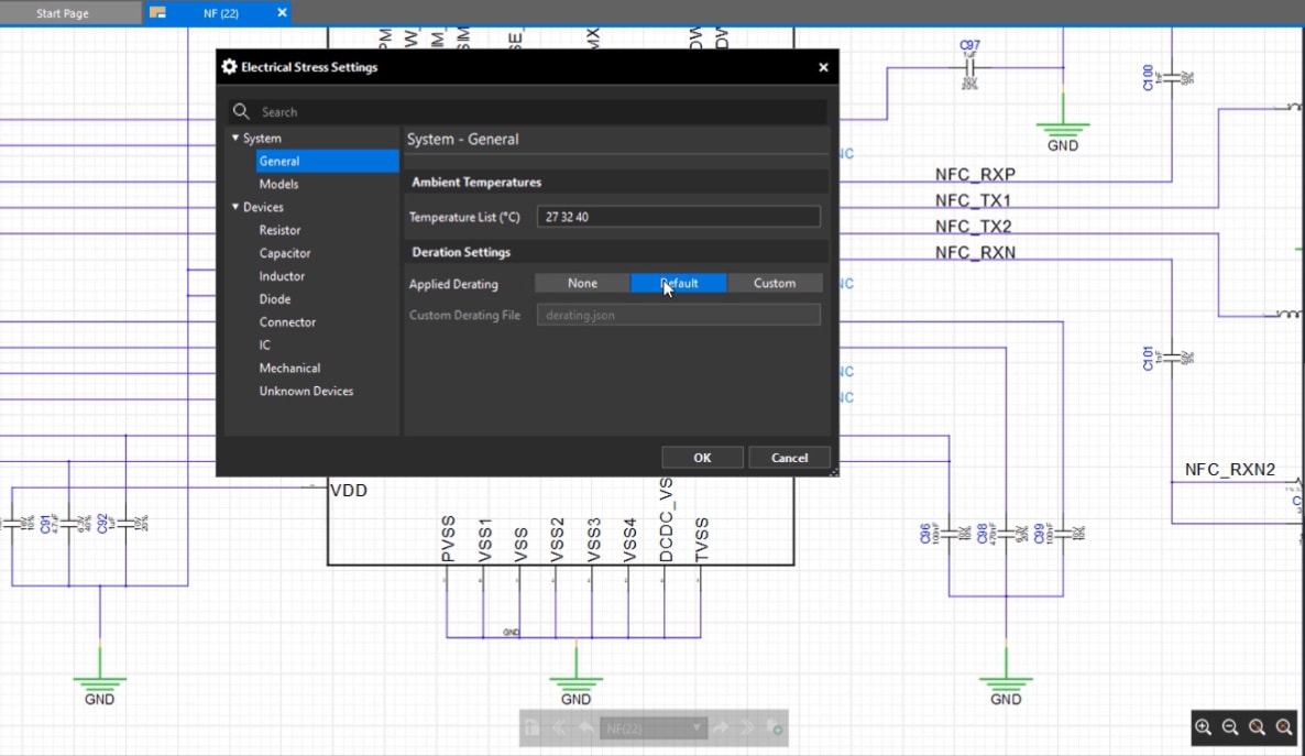
Electrical stress settings configuration panel in Allegro X System Capture
Allegro X for PCB Design with Electrical Stress Analysis
In aerospace PCB design, the Allegro X System Capture features for electrical stress analysis provide essential tools to ensure reliability and prevent field failures. The integrated reliability analysis allows designers to simulate their entire circuit without the need for SPICE or proprietary models, making it easier to identify overstressed components.
Designers can configure electrical stress settings specific to their design by inputting desired test temperatures and applying property derating to components. With a single click, they can analyze the electrical stress within the circuit and use a customizable results dashboard to get an overview of analyzed devices, categorized by their stress levels.
This functionality allows for easy toggling between different reporting views and stress levels, as well as real-time search and filtering for specific components. For instance, if a capacitor is found to be overstressed, it can be quickly replaced with a higher-rated part, and the analysis can be rerun to ensure the updated design is robust. The results can also be exported as PDFs or CSVs for team sharing, facilitating early identification and prevention of component failures.
Design for Aerospace Reliability with Allegro X
Additionally, Allegro X System Capture design for reliability features help aerospace PCB designers produce robust circuits by allowing for early identification and correction of potential failures. The customizable results dashboard provides an overview of component analysis, enabling quick identification of overstressed components and design violations.
Designers can filter by component types, such as capacitors, and cross-probe to the schematic to replace parts easily. Once adjustments are made, the analysis can be rerun to verify that components are within their limits.
Furthermore, schematic integrity checks can be configured before running a design audit, with the ability to filter by protocol checks and categorize issues by severity (information, warnings, or errors). By addressing these issues early on, designers can ensure that their circuits meet the rigorous reliability standards required for aerospace applications.
Understanding and adhering to aerospace PCB design standards is crucial for ensuring the reliability and performance of PCBs in extreme environments. For further information on how Cadence can support your aerospace PCB design needs, visit our PCB Design and Analysis Software page and explore the powerful features of Allegro X for reliability analysis and robust design verification.
Leading electronics providers rely on Cadence products to optimize power, space, and energy needs for a wide variety of market applications. To learn more about our innovative solutions, talk to our team of experts or subscribe to our YouTube channel.