OrCAD X and Allegro X
Key Takeaways
-
OrCAD X and Allegro X are the latest upgrades from the respective Cadence circuit design software.
-
Allegro X offers additional functionality, but both are extremely capable of meeting the challenges of modern-day printed circuit DFM.
-
A 30-day free trial of OrCAD X is available to test the new features and simplified design environment.
OrCAD X and Allegro X give design teams options to decide which tool best suits their organization’s needs.
Finding the best circuit design tool shouldn’t be a massive undertaking: designers or design teams want a solution scalable to their organizations’ needs. Powerful feature sets and ease of use also grace the top of the list – no one wants to spend more time learning a new tool than being able to work in it OrCAD X and Allegro X actively fill this niche as the latest offerings from Cadence’s legendary line of circuit design software, and both have full compatibility with familiar software like Sigrity and PSpice.. No matter the selection, either option carries the renowned performance designers have come to know and love.
OrCAD X and Allegro X at a Glance
|
OrCAD X PCB Editor has… |
Allegro X PCB Editor additionally has… |
|
|
What’s New With OrCAD X?
OrCAD X is the latest release of the OrCAD design platform, intended to provide designers with a best-in-class and comprehensive PCB design and layout environment with the new OrCAD X Presto PCB Editor. The focus of OrCAD X is to streamline and simplify the usability and customization of tools to keep designers engaged with the board design. The new user interface makes it easy to accelerate printed circuit development with these key features:
-
Live DOC - Documentation can be the last thing a designer wants to deal with at the end of a rigorous layout. Yet inconsistencies, ambiguities, and errors in manufacturing documents can scuttle precious work hours and dollars on revisions. Live DOC automates this process, ensuring accurate translation from design intent to documentation and quicker documentation output overall. Because Live DOC automatically synchronizes documentation to the board file, designers have no fear that board manufacturing files and the current revision are unaligned. Users can rapidly edit standard templates pre-output or adjust document layouts to suit the needs of manufacturers and internal organization records.
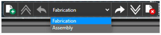
Users can select from templates to quickly generate manufacturing documentation.
-
Design Markup - Printed circuit design and manufacturing is an intensely collaborative process spanning diverse disciplines; communication is vital because of the stakes involved with production timelines and budgetary constraints. Comments and markups from Design Markup highlight critical design information for review and easy recall. Design teams can archive this information for record-keeping to exclude internal-facing markups with potentially sensitive data from externally shared project documentation.
-
3DX Canvas - MCAD-ECAD integration is becoming increasingly critical as form factor and enclosure challenges grow. Designers must be able to visualize the entirety of their device to facilitate a proper fit between the printed circuit(s), cable assembly, and other sub-system elements. OrCAD X supports this endeavor by allowing user-defined cutting planes in any combination of the x, y, and z-axes. Additional visibility features, like the ability to assign colors to create a manufacturing-similar visualization or adjust layers' opacity, further empower user customization in the 3D view mode. DRC violations and air gap measurements are also viewable in 3D.
How Allegro X Further Simplifies DFM Workflow
For design teams looking to push their printed circuit design capabilities even further, Allegro X PCB Editor has shared functionality with OrCAD X Presto PCB Editor (including cross-compatibility between file types) with enhancements that provide expert real-time feedback on the layout’s performance. New refinements in Allegro X PCB Editor include a greater emphasis on streamlining manufacturing. Whether rigid-flex or complex drilling (microvias, counterbores, countersinks, etc.), users can expect a slate of tools that minimize revisions:
-
Rigid-flex - For the layout team, the difficulty of working with flex materials is the broad span of electrical and mechanical properties a typical layout may encounter. Users can define zone boundaries that flag a DRC violation if all of a component’s pins don’t land within the same boundary. It’s even possible to specify a nested zone where manufacturing requirements for the innermost zone diverge from the outer; these nested zones will require a separate stackup as the driving document. Fortunately, the Fill-In Material column of the Cross-section Editor is a perfect solution: users can import or export Cross Section files to correct construction. Data from the Cross-section Editor is consumable by Sigrity for more accurate simulations.
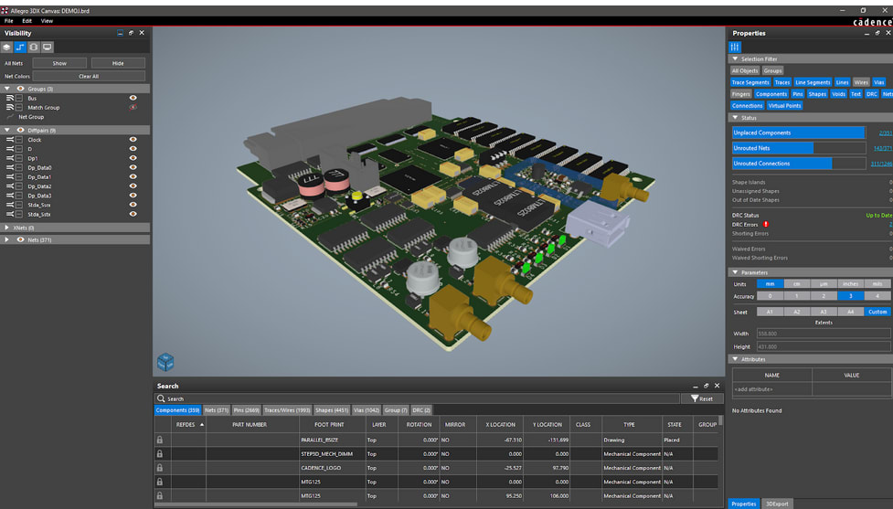
The new 3DX Canvas supports flex and rigid-flex assembly modeling.
-
Drill settings - Users can now designate countersink/counterbore options from the secondary side, with the corresponding drill information automatically included in the NC Drill Legend for the fabricator. Padstack creation allows microvia slot drilling and defining drilled hole dimensions pre-plating for connectors with tight tolerances.
-
Creepage/clearance settings - Users can set a high-voltage constraint that checks for distance violations along the surface (creepage) and through the air gap (clearance). A quick simulation result informs designers which part locations exceed the maximum allowable voltage – a welcome benefit in high-power boards.
Speaking of power, Allegro X PCB Editor users can leverage the Power Plane Generator to create dynamic planes. Parameter adjustment allows for more advanced control of plane dimensions to reduce unnecessary necking that increases impedance, starving power and generating excess heat. By default, plane generation does not require additional settings, but users can select from Via, Plane, and Outline options for more explicit plane design.
Whether OrCAD X or Allegro X, Cadence Powers Next-Gen Design
Designers interested in OrCAD X or Allegro X are well served to see how easy and powerful circuit design can be. And just like their predecessors, OrCAD X and Allegro X have the support of Cadence’s PCB Design and Analysis Software for a seamless and thorough dsign process.
Leading electronics providers rely on Cadence products to optimize power, space, and energy needs for a wide variety of market applications. To learn more about our innovative solutions, talk to our team of experts or subscribe to our YouTube channel.