Circuit Board Testing for Manufacturing Verification
Key Takeaways
-
The need for automated circuit board testing.
-
Types of circuit board testing systems.
-
Design for test (DFT) recommendations for full PCB test coverage.
Automated circuit board testing with a flying probe test system
Circuit board testing usually brings to mind images of technicians armed with probes and scopes, checking and debugging assembled boards. The job of these technicians is to test the functionality of the board and look for design problems that need correcting or circuitry performance that needs enhancing. While this method of testing is an essential part of the electronics development cycle, it isn’t the only verification process that the board will go through.
The mass production of circuit boards requires a combination of automated and manual component assembly processes. These processes position parts on a board and then solders them in place. The job of validating these assembly processes falls to automated circuit board testing systems that confirm whether the board has been correctly manufactured. Let’s take a deeper look into automated testing, and what circuit board layout designers need to do to best accommodate this testing.
Automated Circuit Board Assembly: What Needs to Be Tested
There are three different automated processes used for assembling printed circuit boards: wave soldering, re-flow soldering, and selective soldering.
Wave Soldering
Used mostly for thru-hole components, the circuit board passes through a wave of molten solder that wicks up through the holes of the board and around the inserted pins forming a solder joint. Wave soldering can also be used for some surface mount components, but often these parts have to be isolated from the wave.
Solder Reflow
Mainly used for surface mount components, the parts are “glued” onto the metal pads of the board with a solder paste made up of metal solder particles and flux with a sticky consistency. Once all the components are in place, the board is passed through an oven and heated until the solder paste melts or re-flows, forming a solder joint between the part and board.
Selective Soldering
This system uses molten solder pumped up from a reservoir through a nozzle to deposit solder directly on specified locations. Although slower than the other two systems, selective soldering enables automated assembly of thru-hole pins that are difficult for wave soldering.
While modern electronics could not be built today without these automated assembly processes, there always is the possibility that soldering problems may occur. To find these errors, automated testing is used to detect whether or not each component pin is soldered correctly to its corresponding pin or hole on the board. Here are some of the soldering problems that can happen during automated PCB assembly:
- Solder shorts: With the larger pin-counts and smaller pin-pitches of the electronic components in use today, there is an increased possibility of solder bridging between two or more pins. This situation will result in an electrical short between the bridged pins.
- Sunken joints: Thru-holes can sometimes fail to retain the solder that has wicked up through the hole before it can create a good solder joint. In this case, the solder joint could easily be broken or not exist at all.
- Insufficient solder: When components are not placed optimally for the wave solder, larger parts can sometimes prevent smaller parts behind them from getting enough solder for a good connection.
- Incomplete connections: Circuit boards that are not optimized for solder reflow can sometimes inhibit the proper amount of airflow in the oven, preventing some connections from getting enough heat to form a good solder joint.
To find these solder joint problems, manufacturers rely on automated PCB testing systems. Next, we’ll see what these systems are and how they are used.
Testpoint locations flagged in a PCB CAD system
Types of Automated Circuit Board Testing Systems
There are many methods of examining a circuit board, from manual tests conducted by technicians with various diagnostic tools to different automated test systems. Additionally, there are also different inspection tools used to visually validate PCB assembly. These tools include X-ray equipment and automated optical inspection (AOI) systems. But the automated test systems we are focusing on involve probing designated points on the board to validate solder connections, which can be separated into two main types: in-circuit tests and flying probe systems.
In-Circuit Tests
Commonly known as ICT, in-circuit test systems use a uniquely created fixture with precisely placed probes and an associated test program to test each board developed. The fixture’s probes will contact each test point on the board, allowing the system to simultaneously test all the connections on the board very quickly. Although most boards are tested from the bottom, some ICT systems will test both sides of the board at the same time. The test fixture is designed to draw the boards down onto the spring-loaded probes with a vacuum seal to ensure the electrical connectivity of the probes to their corresponding testpoints on the board.
ICT fixtures are expensive and time-consuming to develop and build and can be difficult to modify to match enhancements or modifications in the PCB design. For this reason, ICT systems are usually reserved for mass production of proven designs to test large quantities of circuit boards quickly. ICT systems can also be used for some functional testing of the board in addition to its assembly validation tasks.
Flying Probe Systems
These test systems use probes to test the same testpoints on a circuit board that the ICT system uses. The difference, however, is that a flying probe system doesn’t use an expensive test fixture. Instead, it moves a handful of probes around the board to test each net sequentially.
The individual testing of each testpoint causes the flying probe system to be much slower than ICT, and without multiple simultaneous connections, it cannot conduct functional testing. However, where flying probe testing shines is in the setup and expense, which is minimal. Not only can a circuit board be readied for testing quickly, but any changes to the PCB design can be easily reprogrammed into the system. This makes the flying probe test system ideal for prototype production of circuit boards going through multiple design changes and interactions in their development. Flying probe testing is also useful for limited production runs of circuit boards or larger boards that ICT cannot accommodate.
Now that we’ve talked about the type of test systems used to validate PCB assembly, it’s time to turn our attention to the design requirements of circuit boards for this testing.
Setting up padstacks that can be used for testpoints in Allegro X
Preparing the Circuit Board Layout for Automated Test
We’ve been talking a lot about where the probes of an automated test system contact each circuit on the board, and these contact locations are called testpoints. To be clear, testpoints differ from actual probe points, which are easily accessible locations for a technician to probe critical nets of the board. Probe points are typically marked with their net, such as “GROUND,” and often have a post soldered into them for the technician’s test leads to clip onto.
Testpoints, on the other hand, are exposed areas of metal on the board that have enough clearance around them for the test system’s probes to contact. Thru-hole pins are usually the first choice for a testpoint if the board has thru-hole parts on it. Otherwise, existing vias can be flagged as testpoints, or new metal pads can be added and flagged as a testpoint as required. In the picture above, you can see some of the padstack selections available for testpoints in a typical PCB CAD system. Testpoint pads are often round, but designers sometimes use square shapes to make them easier to find on the finished PCB. Many different types of probe tips can be used for automated testing, including conical, flat, spherical, or others, depending on whether the testpoint is a metal pad, via, or thru-hole pin.
When flagging thru-holes or vias as testpoints or adding testpoint pads, there are a couple of design rules that PCB layout engineers need to keep in mind:
- Grids: Some manufacturers prefer testpoints to be on grid, so check with your assembler before you begin the layout of the board.
- Spacing: This will change depending on your manufacturer, but 75 mils spacing between testpoints is a good value to start with. However, the safe bet is to check first.
- Clearances: These also change depending on who is building the board, but often manufacturers require 50 mil clearances to components and pads, and 100 mils to the edge of the board for a good vacuum drawdown.
- Board side: Many manufacturers can test both sides of the board simultaneously, but be sure to check first.
- Coverage: For full test coverage, each net of the design needs to have a testpoint on it.
Once the testpoints are completely installed on the printed circuit board layout, you can create the testpoint files needed for the manufacturer to build the test fixture or program the system. This data usually consists of an XY location file containing each testpoint on the board as well as the net it is assigned to and a complete netlist of the design. Usually, this data can be extracted automatically from the PCB CAD system you are using, along with many other useful testpoint functionalities that we will explore next.
Some of the Testpoint Parameters that can be set up in Allegro X PCB Editor
Putting Your PCB Design Tools to Work
Before you start adding testpoints to your design, the CAD system will have multiple parameters that can be set up. These will include items like specifying a testpoint grid if you want one, selecting what design elements can be flagged as a testpoint, and what padstacks can be considered for converting to testpoint locations. You can also set up the text that will be used for denoting testpoint identification references (again, only if you want them), and unique testpoint clearances to other design objects. You can see some of these choices in the Automatic Testprep options in Allegro X PCB Editor, shown above.
Once your parameters are set up, you can start flagging testpoint locations. Typically, this is done automatically, although you also can manually select which design elements will be flagged as testpoints. Once circuit board testing is complete, you can export testpoint design data in the file formats required by your manufacturer.
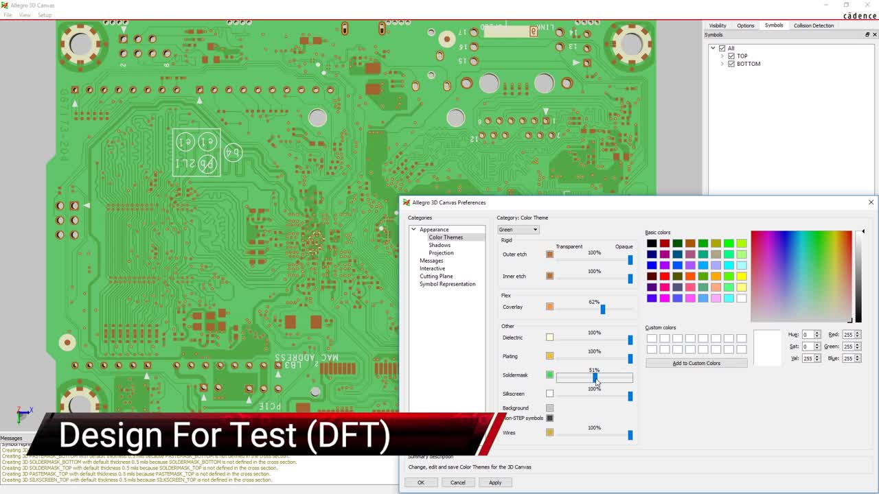
Allegro X has many other PCB test features that can help with circuit board testing, such as the design for test functionality shown in the video at the top of this article. For more information on designing your printed circuit board for full testability, take a look at this E-book.
If you’re looking to learn more about how the Allegro X Design Platform has the solution for you, talk to our team of experts.