Showing Components in 3D with OrCAD X
Key Takeaways
- OrCAD X enables detailed 3D visualization of PCB components.
- Seamlessly map mechanical enclosures with the advanced features in OrCAD X.
- Utilize the visibility panel to toggle component visibility and adjust opacity.

The 3D engine in OrCAD X allows you to easily show components in 3D.
OrCAD X enables 3D functionality that facilitates the design, review, and verification of PCB designs. Designers can configure component visibility, add and map mechanical enclosures, and adjust 3D view options. This allows for inspecting components and interactions, including visibility toggles, opacity adjustments, and measurements between objects. To show components in 3D using OrCAD X, start with the Visibility Panel.
The Visibility Panel in OrCAD X
How to Show Components in 3D Using OrCAD X
|
Step |
Action |
Description |
|
1 |
Select 3D Mode |
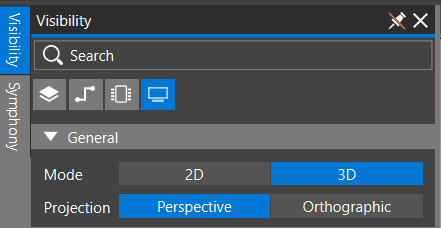
You can access the 3DX viewer in OrCAD X Presto by selecting Visibility to open the Visibility Panel. Next, choose the Display mode tab and select 3D to activate the 3D view of the board. This will allow you to view and interact with the board in three dimensions. This will display settings for viewing the design in 2D and 3D, including components on the TOP and BOTTOM layers, as well as any added mechanical components. |
|
2 |
Use the 3D Control Cube Icon |
Click the 3D control cube icon at the bottom-right of the design canvas to view 3D graphical data. |
|
3 |
Choose Projection Type |
Select the Perspective projection type to view the design from above the center of the assembled board, where objects farther away appear smaller. This is the default option. Alternatively, choose the Orthographic projection type to view the design as if you are directly over each object, with all objects appearing the same size. |
|
4 |
Adjust Layer Visibility |
In the layer toolbar, click on any layer to toggle its visibility within the 3DX canvas. |
|
5 |
Set 3D Object Transparency |
Adjust the slider or specify a value in the 3D Opacity section to set the transparency of 3D objects. The opacity value can range from transparent (25%) to opaque (100%). |
|
6 |
Select 3D Components |
In 3D mode, select the Components tab within the Visibility Panel. Choose 3D Bodies as Model, Place, or DFA. Expand the groups Top, Bottom, and Mechanical to view a list of components placed on these layers. |
|
7 |
Toggle Component Visibility |
Click on a component from the list and use the visibility icon to toggle its visibility. Repeat this process to modify the visibility of individual components or use the header-level visibility icon to disable visibility for all components in a group. |
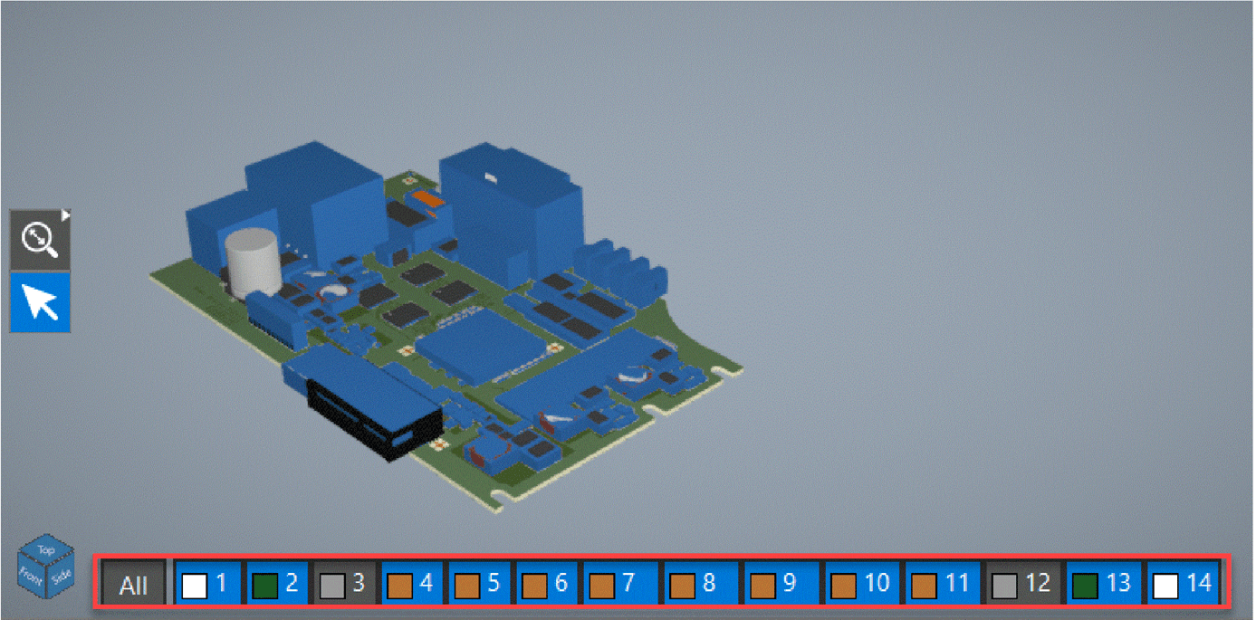
Toggling layer visibility, associated with step 4
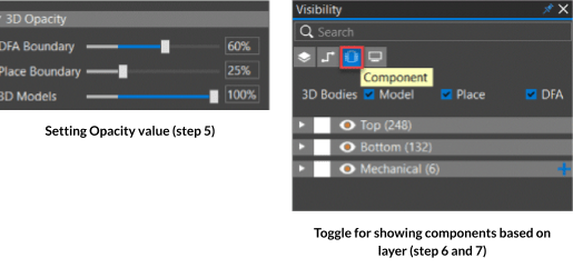
Setting opacity and showing components based on layer in OrCAD X.
Integrated 3D Capabilities in OrCAD X
Showing Enclosure Components in 3D
The OrCAD X 3D mapper feature enables seamless integration with mechanical components and enclosures. As PCBs become denser and product form factors shrink, ensuring that the board properly interacts with mechanical elements in the final assembly is crucial in avoiding mismatches. Traditionally, incorporating 3D models of cases, connectors, and hardware—typically sourced from MCAD teams or external vendor websites—into the PCB design has been a cumbersome process, often plagued by alignment and orientation challenges.
OrCAD X addresses these challenges by supporting various native CAD formats, including STEP, Dassault Systèmes SOLIDWORKS, Siemens NX, Autodesk Inventor, and PTC Creo. Its powerful automatic mapping algorithm allows designers to align and orient components with a single click, significantly streamlining the mapping process.
3D Design Rule Check Errors
The OrCAD X environment helps streamline the detection of placement errors in 3D designs. The software allows for the easy definition and application of 3D clearance rules via its constraint manager, while the properties panel indicates any 3D Design Rule Checks (DRCs). Users can delve into specifics with a pie chart that categorizes the types of 3D DRCs encountered, and clicking an error directly in the search panel navigates you to the problematic area on the canvas, where corrections can be made in both 2D and 3D views.
For those working with rigid-flex designs, defining flex and bend zones is made simple by selecting the design outline in the properties panel. Users can then determine if zones or bends have been set and make adjustments, as needed by unlocking and altering bend lines directly. This flexibility extends to visualizing bends in 3D after defining them in 2D, allowing for dynamic adjustments.
Model Visibility Control
OrCAD X also offers enhanced visibility controls within the components tab, where users can adjust the transparency and visibility of models and enclosures for better focus during design reviews. It supports importing mechanical files in various formats, enabling precise alignment with PCB elements. This holistic approach ensures that the mechanical components integrate seamlessly with the electronic design, providing a comprehensive and interactive 3D visualization that ensures design integrity from the outset.
By leveraging OrCAD X, designers can efficiently show components in 3D. Through OrCAD X 3D tools, design reviews, and verification processes can be streamlined, reducing errors and enhancing productivity. Discover more about how Cadence's solutions can optimize your design workflows by visiting our PCB Design and Analysis Software page and exploring OrCAD X.
Leading electronics providers rely on Cadence products to optimize power, space, and energy needs for a wide variety of market applications. To learn more about our innovative solutions, talk to our team of experts or subscribe to our YouTube channel.