MTBF and Reliability Standards in PCB Design | Cadence
Key Takeaways
-
MTBF quantifies the average operational lifespan of devices.
-
Various standards like FIDES and MIL-HDBK-217F guide MTBF analyses.
-
Allegro X System Capture integrates MTBF analysis with Electrical Overstress (EOS) results for comprehensive design evaluations.
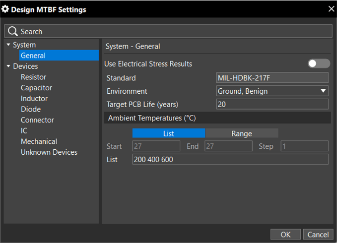
Access the Design MTBF Settings dialog box by choosing Configure — Design MTBF Settings from the Design Integrity menu.
What is Mean Time Between Failure (MTBF) Analysis and Why is it Useful?
Mean Time Between Failure (MTBF) is used to predict the reliability and operational longevity of a device, system, or printed circuit board. It quantifies the average time that a device is expected to operate without failure. This metric is useful for estimating the reliability of products over time and planning maintenance schedules.
Importance of MTBF
MTBF serves as a single, comprehensive metric that communicates a product's reliability. By analyzing MTBF, engineers can anticipate potential failures and take steps to mitigate them, enhancing product longevity.
Leveraging MTBF in System Capture
In Allegro X System Capture, MTBF analysis can be integrated with Electrical Overstress (EOS) results. This integration allows for a thorough evaluation of a design against electrical stress, allowing designers to better predict operational lifespan.
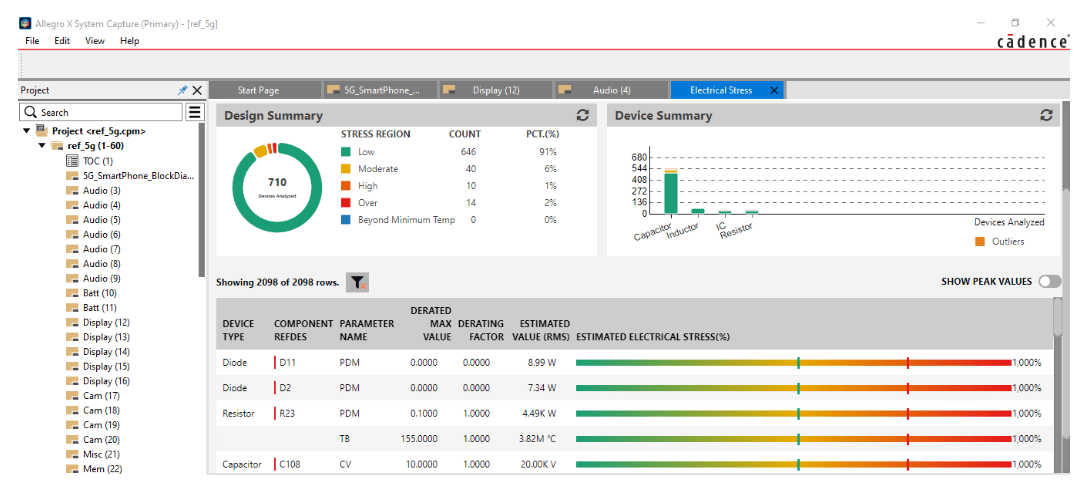
Electrical stress analysis window.
MTBF and Reliability Standards for Specific Industries
Failure In Time/Duration Equivalent Standard (FIDES)
FIDES is used across many high-reliability industries including aeronautics, military, transportation, space, telecommunications, and data processing. This standard takes into account a variety of factors such as:
-
Electrical Overstress (EOS)
-
Operating Temperature
-
Thermal Cycling
-
Vibration
-
Relative Humidity
-
Pollution Level
-
Process Quality
-
Manufacturing Quality
By considering these variables, the FIDES standard can provide an assessment of a product’s reliability in demanding environments.
Other Standards
Apart from FIDES, several other standards are available in MTBF analyses, including Siemens SN29500 and MIL-HDBK-217F. These standards provide guidelines tailored to specific applications and industries, ensuring that reliability assessments are aligned with the products' operational contexts.
Manual Calculation of MTBF: Challenges and Limitations
Manually calculating the Mean Time Between Failures (MTBF) has been common practice, especially when evaluating the reliability of electronic components or systems. The manual process typically involves calculating the failure rate (λ) for each component and then determining the MTBF as the reciprocal of this rate. The challenge lies in accurately determining the failure rates, which can vary significantly depending on factors such as the operating environment, thermal stress, and load conditions.
Challenges of Manual MTBF Calculation:
-
Complexity and Time-Consumption: Manually calculating MTBF requires detailed knowledge of each component's failure rates, which are often derived from standards like MIL-HDBK 217F or Siemens SN 29500. This process can be extremely time-consuming, especially for designs with numerous components.
-
Inaccurate Failure Rate Estimation: Failure rates are determined through various methods, such as the "Parts Count" method or a more detailed analysis based on electrical stress and thermal conditions. The "Parts Count" method, although quicker, is often less accurate, leading to unreliable MTBF estimates.
-
Difficulty in Accounting for Environmental Factors: Accurately incorporating environmental conditions such as temperature and humidity into the manual failure rate calculation is challenging. These factors are critical to reliability, and overlooking them can lead to significant underestimations or overestimations of MTBF.
-
Limited Visualization and Analysis Tools: When calculated manually, MTBF results are often presented in basic tabular formats without advanced visualization. This makes it difficult to quickly identify reliability issues or compare results across different operating conditions.
Benefits of Using Allegro X MTBF Analysis Solution:
-
Automated and Accurate Calculation: The tool automates the calculation of MTBF based on the latest electrical stress data and environmental conditions, ensuring higher accuracy. By selecting recognized reliability standards like MIL-HDBK 217F or FIDES, users can be confident in the reliability estimates produced.
-
Comprehensive Visualization: The MTBF results are presented in a dynamic dashboard with temperature tabs, bar charts, and doughnut charts. This makes it easier to visualize reliability trends and identify components with low MTBF that may require design changes.
-
Error Resolution Support: The solution not only calculates MTBF but also helps users address any reliability issues flagged during the analysis. Users can directly navigate to
problematic components in the schematic and make necessary adjustments, improving the overall design reliability. - Efficient Reporting and Data Management: Users can generate detailed MTBF reports in PDF or CSV formats, making it easier to share and document reliability analysis. The reports are synchronized with design data, ensuring consistency and accuracy.
Applying MTBF Analysis to Designs With Allegro X
With Allegro X MTBF analysis, designers can optimize elements of their design, particularly in component selection. For example, if MTBF analysis within Allegro X System Capture reveals that a product has an MTBF of approximately 3 years, but the product specification requires a 5-year operational life, designers can adjust the design or modify operating conditions to meet the specification.
Utilizing Live BOM for Component Selection
When MTBF analysis indicates the need to change components due to operating conditions, features like Live BOM in Allegro X System Capture can be invaluable. Live BOM helps identify components with the desired properties, thus increasing the MTBF metric and ensuring the design meets reliability standards.
Avoiding Over-Design
MTBF analysis can also reveal instances where a design may be over-engineered for reliability. This insight allows designers to consider cost optimizations while still meeting product specifications or MTBF standards, ensuring that resources are used efficiently.
Planning Maintenance
Understanding the MTBF of a product is crucial for maintenance planning. Knowing when a product is likely to fail enables timely maintenance, preventing unexpected downtime and ensuring continuous operation.
Running and Interpreting MTBF Analysis in Allegro X System Capture
Configuring MTBF Settings
To conduct an MTBF analysis, configure the design MTBF settings by selecting the appropriate standards (such as MIL-HDBK-217F or FIDES) and setting the target PCB life expectancy. These settings influence the analysis and ensure it aligns with industry requirements and operational goals.
Conducting the Analysis
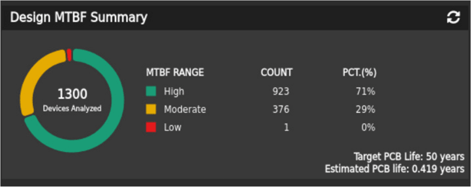
Once configured, MTBF analysis can be run using data from the last electrical stress analysis or based on newly defined settings. The results are displayed in a comprehensive dashboard, highlighting components categorized as Low, Moderate, or High based on their MTBF values relative to the target PCB life.
Results Interpretation
The MTBF results dashboard provides insights into the reliability of each component under various ambient temperatures. It includes tools for filtering and searching specific device types or parameters, making it easy to pinpoint areas that require attention.
Error Resolution
Any errors identified during MTBF analysis can be resolved by navigating to the specific component in the schematic and making necessary adjustments. This iterative process ensures that the design evolves to meet the desired reliability standards.
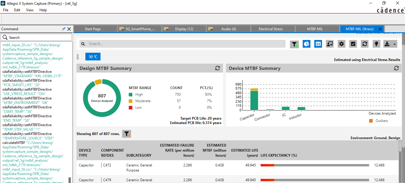
Example image of MTBF stress analysis with a capacitor failure rate 100x of a standard one.
Incorporating MTBF analysis and adhering to reliability standards are crucial for designing robust and durable PCBs. Allegro X designers can seamlessly integrate MTBF analysis. To learn more about how Cadence tools can assist in your PCB design and analysis, visit our PCB Design and Analysis Software page and explore the capabilities of Allegro X.
Leading electronics providers rely on Cadence products to optimize power, space, and energy needs for a wide variety of market applications. To learn more about our innovative solutions, talk to our team of experts or subscribe to our YouTube channel.