PCB Schematic File Formats in OrCAD X
Key Takeaways
-
Learn how .opj files streamline project management by referencing associated schematic and library files.
-
Understand how .dsn files serve as the core blueprint for electrical connections in a PCB project.
-
.olb files define component symbols used in schematics.
Major PCB schematic file formats in OrCAD X
The first major stage of PCB production is the schematic design. When working on a project, it’s crucial to understand how the design is organized on your computer. Each major PCB design software uses its own file structure, but the general principle remains the same:
-
There are file types for individual components,
-
File types for the interactions between them, and
-
File type for managing the project as a whole.
In this article, we’ll focus on pcb schematic file format, specifically in how they apply within OrCAD X, helping users gain a clearer understanding of how these files work together.
OrCAD X PCB Schematic File Format Types Summarized
|
File Type |
File Extension |
Description |
|
Project File |
.opj |
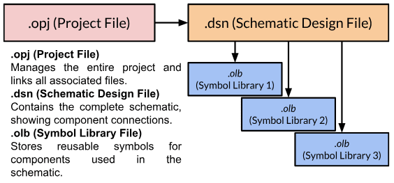
Organizes and manages the entire project. Tracks all associated files like schematics, libraries, and configurations. |
|
Schematic Design File |
.dsn |
Contains the full schematic design, including component connections and references to symbols from libraries. |
|
Schematic Symbol Library |
.olb |
Stores schematic symbols representing electronic components. Used by the .dsn file to build the schematic. |
|
Netlist File |
Various (.dat, .txt) |
Defines the electrical connections between components as derived from the schematic. Although defined in the schematic, used primarily out of it: guiding PCB layout and routing, verifying connectivity, running simulations to validate circuit behavior, and supporting manufacturing and testing processes. |
Understanding PCB Schematic File Formats: An Analogy
Wrapping your head around these various pcb schematic file formats can feel a bit confusing. To make things a bit easier to understand, let’s think of it like a movie production. Each file type plays a specific role, just like the various parts of a movie's creation—scripts, storyboards, and production plans—all working together to bring the final film to life. Using this analogy, we can break down the functions of schematic file formats in a way that makes sense.
.opj (Project File)
Analogy: The Director's Notebook or Production Binder
-
This is the master organizational tool for the movie project.
-
It keeps track of all the scripts, storyboards, cast, shooting schedules, and other documents.
-
If someone needs to know how the movie is structured or where to find specific parts, they look in this notebook.
-
However, the notebook doesn't contain the actual movie script or scenes—it simply points to where those are.
What it does: Keeps the project structured by pointing to the actual design files (like .dsn), libraries (like .olb), and configurations.
.dsn (Schematic Design File)
Analogy: The Movie Script
-
This is the core of the production—it lays out the entire movie, including the plot, dialogue, and scene descriptions.
-
Everything needed to understand how the movie progresses is in the script.
-
However, the script refers to external references (like storyboards or costume designs) for specific details—it doesn’t embed them.
What it does: Contains the full schematic design, showing how components are connected and interact. It references .olb files for component symbols.
.olb (Symbol Library File)
Analogy: The Character Design Sheets or Storyboards
-
These sheets define what each character (or visual element) looks like.
-
They include details like what the character wears, their expressions, and their basic attributes.
-
While the movie script calls for a "hero" or "villain," the design sheets show how they appear visually.
What it does: Holds the visual and logical representations of components (symbols). These symbols are used by the .dsn file to build the schematic.
Technical Details of PCB Schematic File Formats
Now that we understand broadly how they work, let’s delve into the specifics of the major components.
PCB Schematic File Format: .opj Projet File
The .opj file serves as a container or index file for the entire project. It organizes and manages all the files that belong to the design.
-
It does not store the actual schematic data or design content but instead keeps a reference to all associated files, such as the schematic (.dsn), libraries (.olb), and other configurations
-
If lost, the .opj file can typically be recreated by opening the .dsn file, but it’s essential for maintaining project-level organization.
.dsn Schematic Design File
The .dsn file contains the actual schematic design data. It holds:
-
The electrical connections between components.
-
References to component symbols from linked libraries (.olb).
-
Hierarchical and multi-sheet organization for complex designs
The .dsn file links to external .olb files for the symbols. It does not embed the symbols but references them
.olb Symbol Library File
The .olb file is a library of schematic symbols. Each symbol represents an electrical component and includes attributes like:
-
Pin definitions and numbers.
-
Labels for designators and values.
-
Optional parameters like power ratings or tolerances.
The .dsn file references the symbols in the .olb file to visually and logically construct the schematic.
Where do Footprints come in? How are they different from Symbols?
-
Footprints represent the physical layout of the component on the PCB, including pin placements, dimensions, and solder pads.
-
They are stored separately in layout libraries, typically in .dra (drawing) and .psm (physical symbol model) files for OrCAD PCB Editor.
-
Each symbol in the .olb file has attributes or properties that specify its corresponding footprint for PCB layout.
-
These attributes include a footprint name that matches a specific footprint in the layout library.
Back to our analogy, if the schematic is like a movie script, the footprints for the PCB layout are like set designs for filming. They represent where each character (component) stands and interacts in the physical space (PCB).
-
Symbols (in .olb) define the electrical role of a component in the "story" (schematic).
-
Footprints define how that component physically fits into the "set" (PCB).
They are separate but linked—just like the script references specific characters, and the director ensures those characters fit into the right sets.
PCB Layout File File Types
Although not explicitly connected to the schematic, other relevant file types are essential for completing the PCB design process.
-
The PCB layout file (.brd) represents the physical layout of the board, including the placement of components and routing of connections.
-
The symbol drawing file (.dra) defines the physical shape and layout of a component’s footprint, ensuring it aligns with the PCB’s design.
-
The netlist files, typically in formats like .dat or .txt, specify the electrical connections between components, derived from the schematic.
-
The footprint library file (.psm) contains the physical symbol model of a component, which is crucial for accurate placement in the PCB layout.
-
Lastly, the padstack file (.pad) defines the shapes and sizes of pads used in footprints, providing the foundation for reliable component mounting and soldering
Each file type warrants a deeper dive in dedicated articles to fully understand their roles and applications.
Netlist Vs Design File
If the schematic design file (.dsn) is like the blueprint of a house, the netlist is like a list of electrical wiring instructions that specifies how to connect the outlets, switches, and fixtures. The schematic is broader and visual, while the netlist is targeted and precise.
Key Differences of Netlist and OrCAD X Design Files
|
Aspect |
Schematic Design File (.dsn) |
Netlist File |
|
Format |
Binary or proprietary file format for software use. |
Plain text, standardized formats (e.g., SPICE, IPC). |
|
Scope |
Entire schematic design, including symbols and metadata. |
Only the connectivity between components. |
|
Use |
Editable in schematic design tools for circuit building. |
Read by PCB layout tools to guide component placement and routing. |
|
Components & Nets |
Includes components, their properties, and connections. |
Focuses solely on connections between component pins. |
|
Human Readability |
Mostly visual and editable within the design tool. |
Text-based, easy to parse but not editable visually. |
OrCAD X Free Viewer
For viewing these files without a full OrCAD license, Cadence offers the OrCAD X Free Viewer. This tool allows users to open and review various design files, including schematics (.opj, .dsn, .olb), PCB layouts (.brd, .dra), and more.
Leverage Cadence's OrCAD X tools to streamline your PCB design and manage pcb schematic file formats effectively. Visit our PCB Design and Analysis Software page or learn more about OrCAD X.
Leading electronics providers rely on Cadence products to optimize power, space, and energy needs for a wide variety of market applications. To learn more about our innovative solutions, talk to our team of experts or subscribe to our YouTube channel.