PCB Design File Formats in OrCAD X
Key Takeaways
-
how schematic, layout, and netlist file formats like .DSN, .BRD, and .NET form the backbone of PCB design in OrCAD X.
-
Discover how technology parameter files (.TPF, .TCH) and stack-up configurations bridge design and production seamlessly.
-
Understand manufacturing file formats like Gerber, ODB++, and IPC-2581 that ensure accuracy and compatibility with fabricators.
PCB design file formats associated with PCB layout
PCB design file formats work together to bring your PCB designs into the physical world, ensuring every component, trace, and layer detail is accurately represented for manufacturing and assembly. Read on as we discuss PCB design file formats in OrCAD X, from schematic to layout to export.
PCB Design File Formats for Schematic
Major PCB schematic file formats in OrCAD X
PCB design starts with the schematic, and so that’s where we’ll start here too. Discussed in depth in our piece dedicated to schematic file formats, OrCAD X has three major schematic file types to be aware of..
-
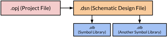
The .OPJ file is a project management file that organizes all related schematic and layout files into a single project. It maintains structure, enabling efficient navigation and linking between schematics, PCB layouts, and simulations. Think of it as the backbone of your PCB project workflow in OrCAD X.
-
The .DSN file is the primary design file for OrCAD X Capture, and it contains the schematic data for your PCB project. It is the starting point for creating and editing circuit designs, holding information like component symbols, netlists, and connectivity details. This file is essential for translating schematic diagrams into PCB layouts.
-
The .OLB file is a symbol library file that contains reusable component symbols, saving time by allowing designers to drag-and-drop parts into schematics. Custom .OLB files ensure your design adheres to specific requirements and standards.
Now, let’s go ahead and move from the schematic to file types associated with your PCB layout.
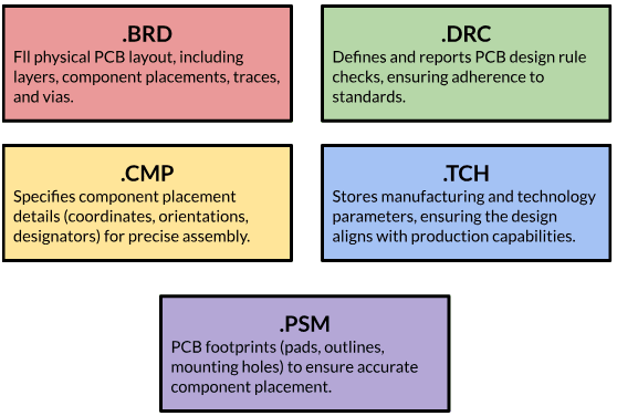
PCB Design File Formats for PCB Layout
|
File Extension |
Description |
|
.BRD |
The .BRD file contains the physical layout of the printed circuit board, including layers, component placement, traces, and vias. This file is crucial for manufacturing and is often exported to formats like Gerber for production. |
|
.DRC |
The .DRC file contains design rule check settings and results. These rules ensure that the PCB layout complies with manufacturing and electrical standards, flagging issues like trace spacing violations or overlapping components. Regularly generating and reviewing .DRC files helps avoid costly production errors. |
|
.TCH |
The .TCH file stores specific manufacturing and technology parameters, such as layer stack-ups, material specifications, and trace width rules. It ensures that your design aligns with fabrication capabilities, bridging the gap between design and production. |
|
.PSM |
The .PSM file stores PCB footprints for components, including pads, outlines, and mounting holes. These footprints are essential for accurately placing components on the PCB layout, ensuring alignment with the schematic design and physical assembly. |
|
.CMP |
The .CMP file provides details about the placement of components on the PCB layout, including exact coordinates, orientations, and designators. This file is essential for assembly processes, ensuring components are positioned accurately. |
Pads-Associated Filetypes: .DRA and .PAD
-
.DRA files define specific pad shapes and sizes for components, such as round, square, or irregularly shaped pads.
-
.PAD files are associated with .DRA files, detailing how pads are implemented across multiple layers (e.g., top, bottom, or internal layers).
Now lets go ahead and dive into some specific, comparing netlist file types.
Comparing Netlist File Types
|
File Type |
Purpose |
Contains |
Use Stage |
|
.LIB |
Logical-to-physical mapping |
Component pin assignments and connectivity |
Schematic to layout |
|
.NET |
Electrical connectivity |
Netlist of connections |
Schematic to layout initiation |
|
.MNL |
Manufacturing netlist |
Post-layout net connections for fabrication |
Post-layout/fabrication |
.LIB – Library File
The .LIB file is primarily a netlist library file that maps logical components from the schematic to their physical representations in the PCB layout. It bridges the gap between the schematic design and layout processes by defining the connectivity (nets) and pin configurations for each component. Key features include:
-
Logical to Physical Mapping: It specifies how a schematic component symbol relates to a physical PCB footprint.
-
Connectivity Information: It includes pin assignments and netlist details for proper routing in the PCB layout.
-
Reusable Data: .LIB files are reusable across multiple designs, making them an efficient tool for standardizing components.
-
Part of the Netlist Flow: It is often used in tandem with .DSN files to generate the .NET file.
.NET – Netlist File
The .NET file is an intermediate file generated from the schematic design that lists all the electrical connections (nets) between components. It serves as a direct input to the PCB layout process, ensuring that the physical connections in the PCB match the schematic design. Key features include:
-
Component Connections: It specifies which pins of components are electrically connected.
-
Input to Layout: This file is crucial for initiating PCB layout, as it tells the layout tool what needs to be connected.
-
Collaboration: Often used to transfer design intent between tools (e.g., from Capture to Presto or other Cadence layout editors).
.MNL – Manufacturing Netlist File
The .MNL file is a manufacturing-specific netlist, generated as part of the PCB layout process. It differs from the .NET file because it includes not just design connections but also physical attributes, optimized for manufacturing and testing.
-
Production-Oriented: Includes information relevant to fabrication and testing, such as pin-to-pin distances, impedance, and physical constraints.
-
Post-Layout Netlist: Unlike the .NET file, which is schematic-based, the .MNL reflects the completed PCB layout.
-
Testing and QA: Used for automated testing systems to verify electrical continuity and functionality in manufactured boards.
Comparing Stackup Files
Similarly, a couple of files are associated with the PCB stackup. Below, we’ll be explaining the differences between them. Note that we’ve already discussed the .TCH and .BRD files above.
.TPF – Technology Parameter File
The.TPF file in OrCAD X focuses on design rules and stack-up configurations customized for a specific technology or fabrication processes. It is similar to .TCH but with focus and flexibility for modern workflows.
-
Custom Stack-Up Parameters: Specifies layer definitions, including thickness, materials, and dielectric constants.
-
Design Rule Configuration: Contains trace width, spacing rules, and via constraints optimized for the chosen fabrication process.
-
Reusable Across Projects: Can be applied to multiple designs to ensure consistency in rules and parameters.
-
Interactive Editing: In OrCAD X, .TPF files allow advanced edits with real-time validation, making them more versatile than .TCH.
|
File Type |
Purpose |
Focus |
Key Difference |
|
.TPF |
Stack-up and rules |
Advanced, flexible configuration for specific tech |
Editable and modernized for OrCAD X |
|
.TCH |
Technology parameters |
Basic layer and trace rules |
Often static and less flexible |
|
.BRD |
Layout data |
Physical board design |
Comprehensive but not technology-specific |
Finally, once you’re ready for export, these are the PCB design file formats associated with PCB export you should know about.
PCB Design File Formats for Export
|
File Format |
Purpose and Details |
Common Extensions |
|
Gerber Files |
- Industry standard for PCB manufacturing. - Represents individual PCB layers (e.g., copper, silkscreen, solder mask). - RS-274X (modern) includes embedded metadata; RS-274D (older) requires aperture files. |
.GBR, .GTL, .GBL, .GTS, .GBO |
|
Drill Files |
- Defines drilling information, including coordinates, hole sizes, and sequences. - Used for vias, mounting holes, and cutouts. |
.DRL, .TXT |
|
ODB++ |
- Comprehensive format combining layer, drill, component placement, and design rules. - Minimizes errors by consolidating all data into a single file. - Often preferred by manufacturers for its completeness. |
.TGZ |
|
IPC-2581 |
- Open, vendor-neutral format for manufacturing data exchange. - Combines connectivity, stack-up data, and design rules into one file. - Gaining traction as an alternative to proprietary formats. |
.XML |
|
DXF |
- Used for exchanging mechanical and outline data with CAD tools. - Supports board outlines, cutouts, and overlays. - Common in workflows that involve enclosure or mechanical design. |
.DXF |
|
Pick-and-Place |
- Provides assembly machines with x/y coordinates, rotation, and layer (top/bottom) for components. - Essential for automating the placement of parts during PCB assembly. - Often exported as a delimited text file for easy processing. |
.TXT, .CSV, .PNP |
|
Netlist Files |
- Defines electrical connections between components. - Used for verification, layout imports, and manufacturing checks. - Ensures the design meets schematic connectivity requirements. |
.NET, .XML |
|
Bill of Materials |
- Lists all components in the design for procurement and assembly. - Includes part numbers, quantities, designators, and specifications. - Exported in spreadsheet-friendly formats for easy review and sharing. |
.CSV, .XLSX |
Although important to know about, you can take the complexity out of managing PCB design file formats with Cadence tools. Explore how OrCAD X can streamline your design-to-production process by visiting our PCB Design and Analysis Software page.
Leading electronics providers rely on Cadence products to optimize power, space, and energy needs for a wide variety of market applications. To learn more about our innovative solutions, talk to our team of experts or subscribe to our YouTube channel.