Unlocking New Features in OrCAD X Presto: A PCB Layout Recap (Webinar Recap)
Key Takeaways
-
OrCAD X Presto features a new UI that focuses on the design canvas, limiting the amount of time designers have to spend in menus or off-screen.
-
The UI carries across the design environment for footprint creation (manual and wizard tool).
-
New features like Analysis Workflow, Constraint Management Panel, and Live DOC help improve manufacturing outcomes.
Unlocking New Features in OrCAD X Presto: A PCB Layout Recap
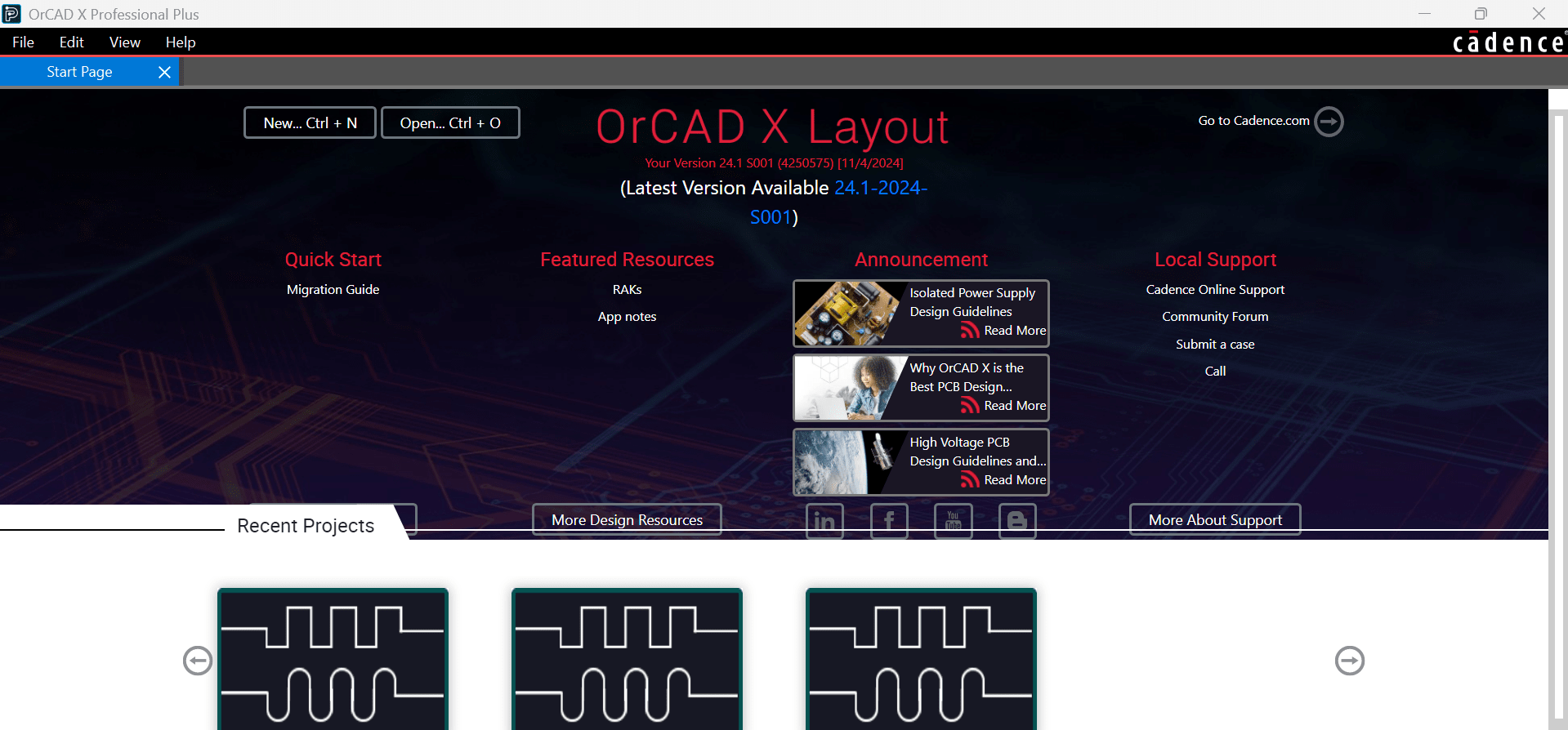
OrCAD X Presto offers designers a customizable, readable UI built on trusted Cadence layout software. Users familiar with OrCAD or Allegro should have no problem becoming accustomed to the tool, but new users may need help navigating it. Unlocking New Features in OrCAD X Presto: A PCB Layout Recap gives designers a broad overview and an in-depth dive into Cadence's new layout tool.
Unlocking New Features in OrCAD X Presto: A PCB Layout Recap
|
UI |
The UI focuses on the design canvas, with panels that users can pin, hide, dock, and rearrange. |
|
Footprints |
Whether creating/editing footprints manually or through the new Footprint Generator, the UI format from the board design remains the same. |
|
Analysis Workflows |
Check design signal integrity with impedance and coupling analysis tools. |
|
Constraint Panel |
Add or edit design rules within a docked menu instead of a separate window. |
|
Design Markup and Review |
Communicate ECOs directly within the project and track the progress of changes with comments embedded within the board design. |
|
Live DOC |
Template-based manufacturing documentation ensures the design sent to manufacturers matches the latest revision. |
A Guide to Unlocking New Features in OrCAD X Presto
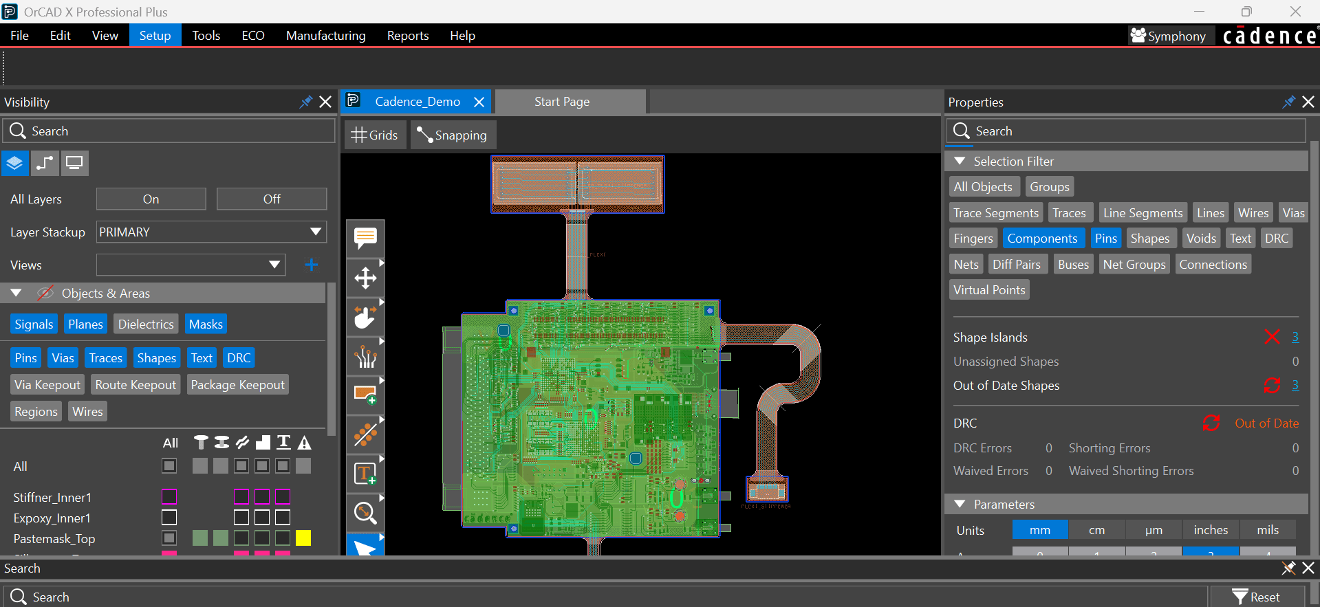
The OrCAD X Presto UI helps designers focus on the board, not menus.
OrCAD X Presto uses a straightforward (and customizable) UI structure:
-
The left side of the window is the Visibility panel, which controls the objects displayed to the user, organized by layer and object type. Users can color-code layers and objects quickly using a rainbow layer distribution for high-contrasting colors and color scaling for different object types on the same layer. Additional Visibility options like Geometries, Components, Manufacturing, Rigid Flex, Surface Finish, and Data Layers give users complete control of what’s present in the design canvas. Preset and customizable Views allow users to lock in multiple visibility and quickly jump between them.
-
The Visibility panel also includes a list of all the nets in the design as defined by the schematic’s netlist in the Nets tab. Using Groups, Diff Pairs, and XNet designations, it’s easy to organize and view similar nets together or assign layer/object overriding colors. Lastly, the Display tab allows users to switch between 2D and 3D views of the design, toggle objects’ net labels, and adjust general visibility like saturation, opacity, and brightness.
-
The top center of the window is the design canvas, where users will shape the board (primarily, placement and routing). A floating toolbar on the left side of the design canvas shows the commands available for the objects within the canvas, like Move, Slide, and Add Connect. Right-clicking on any toolbar icon opens a sub-menu of related commands for object creation or manipulation.
-
Selecting any of these tools will produce an Options menu either docked as a panel on the side of the design or a floating menu within the design canvas (users can toggle between these modes by clicking the command tab above the top of the design canvas or pressing “X” on their keyboard). These command menus show a visual guide for how different options or modes will change how the command interacts with appropriate objects within the design. Similarly, pressing the right mouse button when actively operating a command (e.g., routing a trace) produces a contextual dropdown menu with secondary commands (and their corresponding shortcut commands) for streamlined design navigation.
-
The right side of the window is the Properties panel highlighting various key features, such as the Selection Filter (for narrowing object selection), board completion status, the DRC, and design units. Any hyperlinked text cross-references the Search panel for easier viewing of the corresponding list of objects. Selecting multiple objects of the same type lets users apply changes concurrently across the group, i.e., aligning/rotating/changing layers of multiple components. The Properties panel will update dynamically to match the object type selected with the Selection Filter.
-
The bottom of the window is the Search panel, which allows users to query the design for a specific object or object type. The panel contains a spreadsheet-like tabulation of the different canvas objects, custom net objects, and DRC violations. Users can use additional filter options to search the design objects.
Footprint Creation/Editing
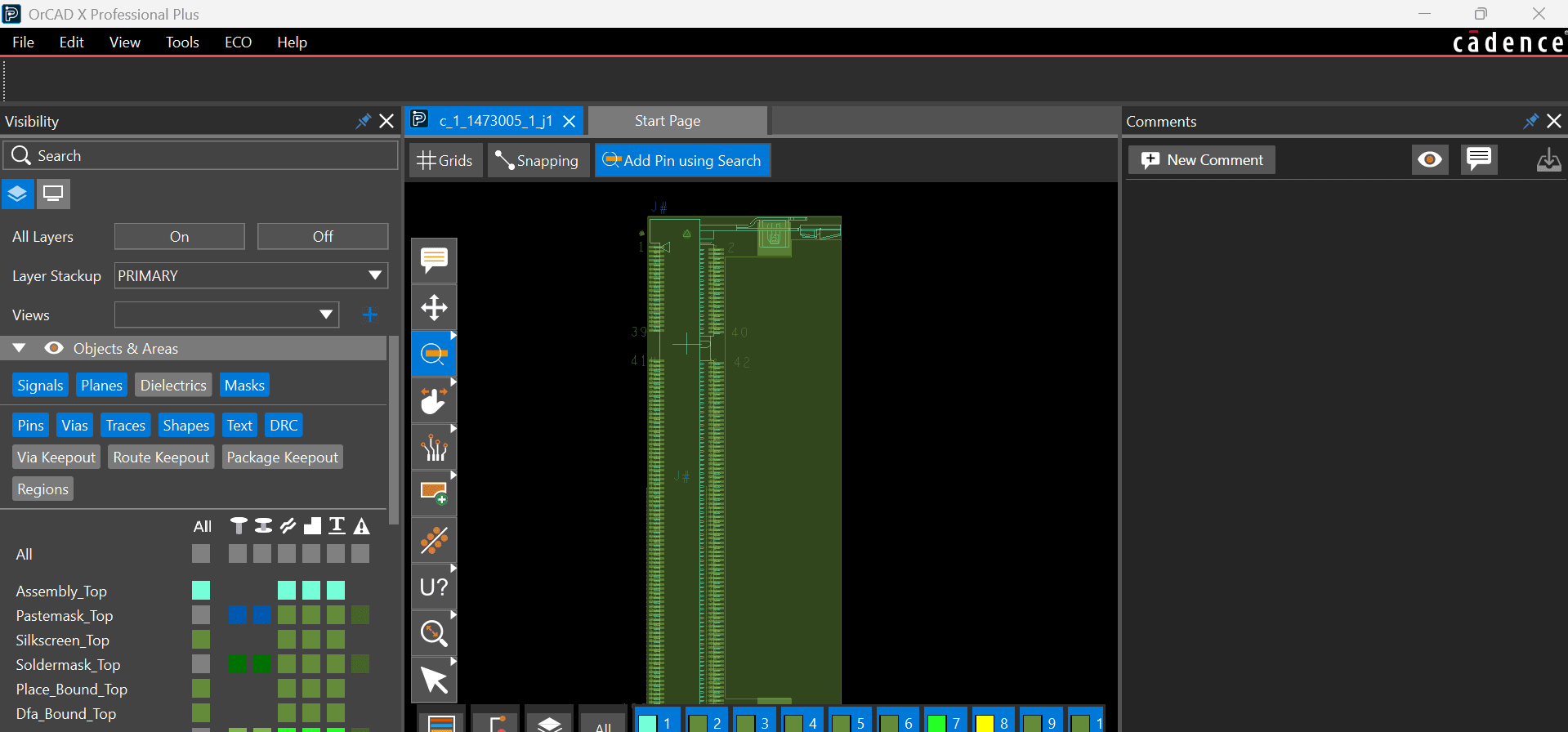
Footprint drawings use the same UI as board files.
One advantage of this UI is that users will see the same features for different project file types in the same locations. For example, opening up a footprint (.drawing or .dra extension) will have the design canvas flanked by the Visibility panel on the left (sans Nets), the Properties panel on the right, and the Search panel on the bottom. The floating toolbar within the design canvas contains additional footprint options: pin-searching and a padstack wizard creation tool.
Footprint Generator
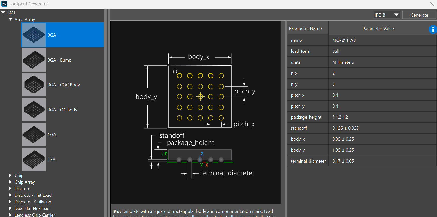
The Footprint Generator makes IPC-compliant padstacks, footprints, and 3D models a breeze.
The Footprint Generator uses a standard set of IPC-defined packages with user-populated geometric data to build footprints, padstacks, and 3D models for standard packages and pinouts. The properties panel displays useful library information, such as the associated pad stacks, the last time a user saved the design, and a comment box for tracking changes. Users can edit the footprint within the wizard by relaunching the Footprint Generator from properties – librarians don’t have to worry about adding or removing multiple versions of the same footprint.
New Design Analysis Workflow Tools in OrCAD X Presto
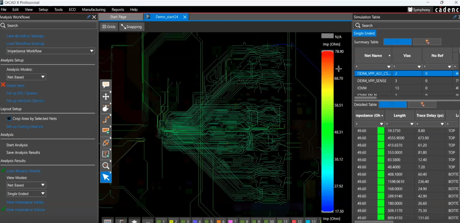
Analysis Workflows give layout designers a tool to check signal integrity.
By launching the Analysis Workflow (under “View” > “Panels” > “Analysis Workflow” in the top navbar), users can investigate the impedance or coupling of the design in visual and tabular formats. After setting the analysis options and running the analysis, users can view all trace segments on a color-coded scale (red = highest, blue = lowest, green = nominal) for single-ended traces and differential pairs. Sliding the top or bottom of the scale, users can see only the impedances/coupling coefficients that fall within the bracketed range (helpful in locating high/low values) and update the design in real time as the design analysis overlays on top of the layout. In the docked Simulation Table, the analysis displays sortable net characteristics depending on the analysis mode in a Summary and Detailed Table:
-
Impedance - Max/minimum impedance, length, via count, delay, inductance, capacitance, resistance
-
Coupling - Net, aggressor net, coupling coefficient, coupling coefficient length
Besides net-based analysis, users can also run directed group analysis, which uses signal drivers/receivers to measure impedance/coupling. With the directed group analysis, users can generate an additional plot that visually indicates the analysis along the trace length (in “Bar/Expanded”) or graph the segments by value/segment length independent of the trace run.
Constraint Panel Update
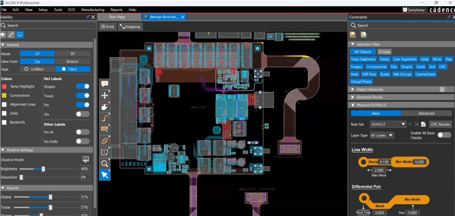
The Constraint Panel facilitates quick editing of the design rules.
New in OrCAD X Presto: users no longer have to navigate to Constraint Manager to view or change their constraint rules – they are conveniently located within the Constraint Panel in the Design Canvas to keep the focus on the layout. Users create a rule set and apply those rules to nets with similar requirements (e.g., power, high-speed, differential pairs, etc.) Like in the Constraint Manager, rules have four categories – Electrical, Physical, Spacing, and SameNetSpacing – with a toggle option for basic and advanced rules.
Design Markup and Review
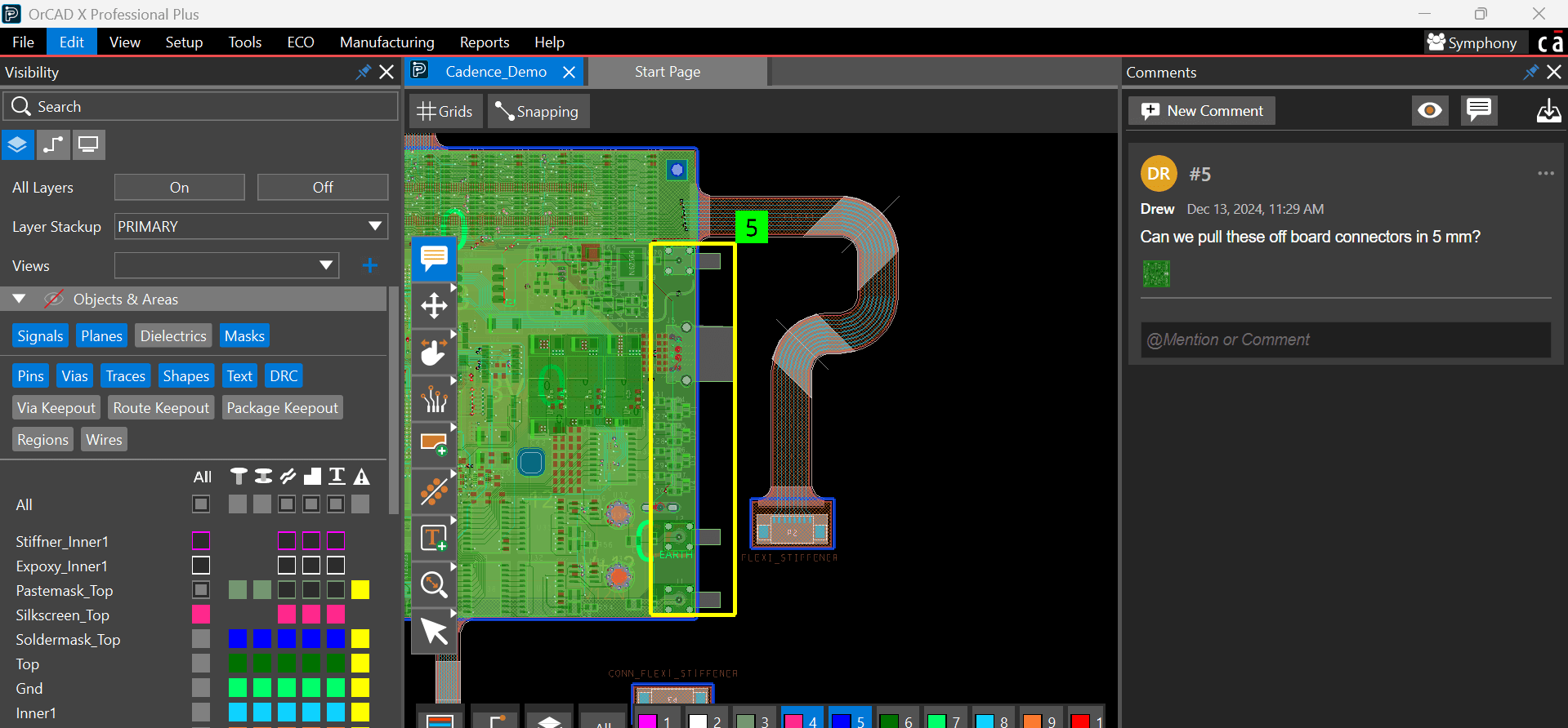
Design Markup and Review keeps communication within the project.
It’s easy for designers, engineers, managers, and others to jump into the design and assign review tasks or communicate directly within the project. Any comments contain a snapshot of how the design appeared at the time, so updates to the board don’t overwrite comments. Team members can reply, resolve, or delete comments to track the review's progress.
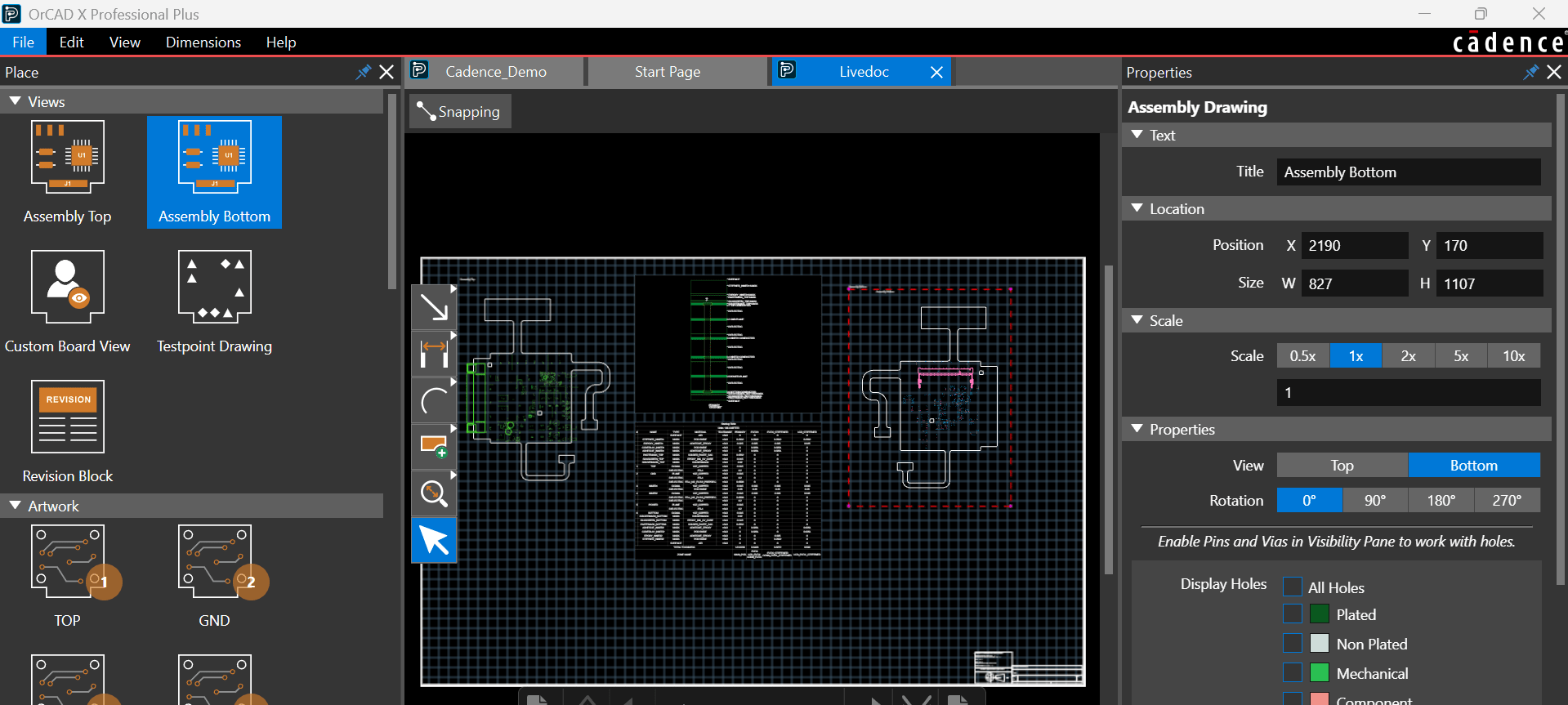
Live DOC template-based manufacturing documentation makes customization easy and clean.
Live DOC is a template-based tool for creating manufacturing documentation. Since the user builds the template that views the current design, unsynced manufacturing documentation cannot be saved or sent. Similarly, organizations need only create a single template for each type of manufacturing document and dimension/annotate accordingly instead of starting from scratch every time.
Cadence Solutions for PCB Layout and More
Unlocking New Features in OrCAD X Presto: A PCB Layout Recap covers some basic functionality and exciting new tools for layout designers. OrCAD X is more than just layout, however, offering designers industry-leading tools for all aspects of PCB project development and revision. Interested in learning more? See the Cadence PCB Design and Analysis Software page for a full list of products that are helping design teams accelerate electronic productions.
Leading electronics providers rely on Cadence products to optimize power, space, and energy needs for a wide variety of market applications. To learn more about our innovative solutions, talk to our team of experts or subscribe to our YouTube channel.