Everything You Ever Wanted To Know About Chamfering in PCB Design
source: wikipedia
Everything You Ever Wanted To Know About Chamfering in PCB Design
Take any corner, cut it off, and you’re left with a chamfer. From your child-proof tables to the iconic walls of the Taj Mahal, humans have long used chamfers to solve corner-related problems both functional and aesthetic.
A chamfer occurs whenever you have two surfaces meeting at an angle other than 90°, especially 45°, but instead of a point they terminate at a flat edge, which has the effect of “rounding” out the corner.
Here are two common reasons chamfering will come up in the context of PCB design.
The first is relatively straightforward—you’re building a PCB that you intend to mate with an edge connector, such as a PCI.
The second is a little less so—it has to do with a commonly touted but misunderstood engineering heuristic: avoid 90° corners when routing your traces in high speed signal designs.
Whether your goal is to build better PCBs for common edge connectors or to improve your trace routing, here’s how chamfering works.
PCB chamfering for edge connectors
An edge connector is a female connector that mates with the contact pads lining the edge of a PCB. Think of those PCI and PCIe slots that make it easy to add memory cards into the motherboard of your PC. When a product supports hardware upgrades, edge connectors are often the standardized interface of choice.
As the designer, it’s your job to make sure your board can easily mate with the standard edge connector on the mating board. That’s where chamfering comes in—you need to ensure that the mating edge of your PCB meets the chamfer angle and tolerances specified by the edge connector manufacturer. You’ll also want to make sure the fabrication house you choose is capable of meeting the tolerances and chamfer angle you desire. To give you an idea, here are some common design parameters you’ll encounter for PC and PCI cards:
-
Chamfer angle: 45° for PC, 20° for PCI
-
Chamfer depth: 0.5 mm for PC and PCI
-
Gold finger spacing: 0.7mm for PC, 2.0mm for PCI
Sometimes you’ll also encounter another term: beveling. The main difference between beveling and chamfering is best summed up with the photo below:
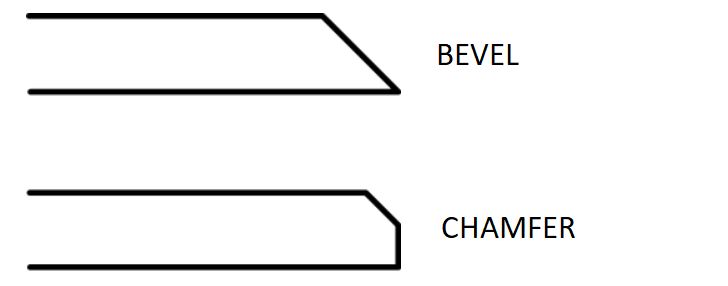
The bevel terminates into a point. Confusingly, sometimes manufacturers will refer to chamfering as beveling when the chamfer angle is not 45°. Others will refer to chamfer angles such as 20° and 30°. Be sure you understand what your manufacturer is referring to when they use this terminology.
Beveling and chamfering are also used during manufacturing to remove burrs from the edges of PCBs to reduce risk of FOD (foreign object debris) that could cause problems with some components.
Chamfering traces: getting to the root of the 90° traces
It’s a rule of thumb you’ve likely heard countless times before: avoid 90° angles when routing traces in high signal designs.
But ever wonder if there was any science to back up that claim? According to Texas Instruments System Design Guidelines for Stellaris® Microcontrollers, the common best practice has little to do with signal integrity:
“The reality is that the signal that the signal-integrity benefits of avoiding 90° angles are insignificant at the frequencies and edge-rates seen in microcontroller circuits (even up to and past 1 GHz/100 ps). [Johnson, H and Graham, M, High-Speed Digital Design: a Handbook of Black Magic, Prentice Hall: New Jersey, 1993.]”
Texas Instruments also cites a report that could find no measurable difference in radiated electromagnetic interference.
So what’s the real reason to avoid 90° angles? Efficiency. You’ll find that most software still continues to encourage the use of 45° angles, and part of the reason for this is far more mundane:
“Routing at 45° reduces overall trace length.”
When you route a trace at 90°, you get a whole extra “half a square” of conductive trace material. If your board is densely populated, sticking to chamfered traces can save you a lot of space, and makes it easier to avoid loops which do cause EMI emissions. You might even say that the root of the 90° corner rule is the fact that all those extra square roots add up.
So if your board is densely populated or you’re going to use an autorouter anyway, those 45° chamfered corners are still the way to go.