Why Your CM’s PCB Design for Manufacturability Rules
Key Takeaways
-
What are PCB design for manufacturability rules?
-
Which PCB design for manufacturability rules should I follow?
-
How can I be sure that my board is adhering to the PCB design for manufacturability rules?
The fall of Rome may have thrown much of the Old World into the Dark Ages; however, it also produced a light that has continued to shine even to this day. This light comes to us in the form of a story, as a legend or perhaps a collection of actual events. Regardless of its origin, the ideals that the Knights of the Roundtable sought to exemplify are worthy of our adoption. As the story explains; however, there was but one ruler, chosen by the sword Excalibur, that could lead his people along the path that shines bright amid the darkness.
Similarly, when designing PCBAs, there is one set of rules that leads to an optimal manufacturing process flow and the best-built boards. Neglecting to follow these constraints, will undoubtedly expose your boards to perils that may delay or even stall the manufacturing process. Yet, by acquiring and following your contract manufacturer’s (CM’s) design for manufacturing rules as we describe below, the building of your PCBAs can avoid unnecessary and costly back and forth, design changes and response.
What Are Design for Manufacturability Rules?
Although most of us probably think that there are far too many rules and many are too restrictive, constraints can be useful. A prime example are the guidelines and rules within which PCBs must be built. All circuit boards are categorized as either class 1, class 2 or class 3 according to IPC-6011. And this partitioning provides the level to which board construction must attain in terms of acceptable errors. Perhaps, more importantly, specific ranges and values for circuit board and PCB layout parameters, some of which are listed below, are given.
Common Circuit Board and PCB Layout Parameters
- Board edge clearance
- Drill hole aspect ratio
- Annular ring size
- Creepage and clearance distance
- Solder mask clearance
The parameters listed above and others that define PCB manufacturing restrictions are collectively known as design for manufacturing or design for manufacturability (DFM) rules, which can be defined as:
Design for manufacturing or design for manufacturability (DFM) rules and guidelines include all specifications and choices included as part of the design package file(s) that are required or aid the manufacturer in building the circuit board that embodies the design intent.
DFM includes rules that are targeted especially for board fabrication, sometimes referred to as design for fabrication (DFF), and for assembly, known as design for assembly (DFA). Instituting DFF and DFA into board design is not simply useful, but a mandate. However, there are multiple implementation strategies for DFM and DFA and your choice along with the source of the rules determines whether the boards are produced efficiently or manufacturable at all.
Choosing the Best Manufacturing Rules for Your Design
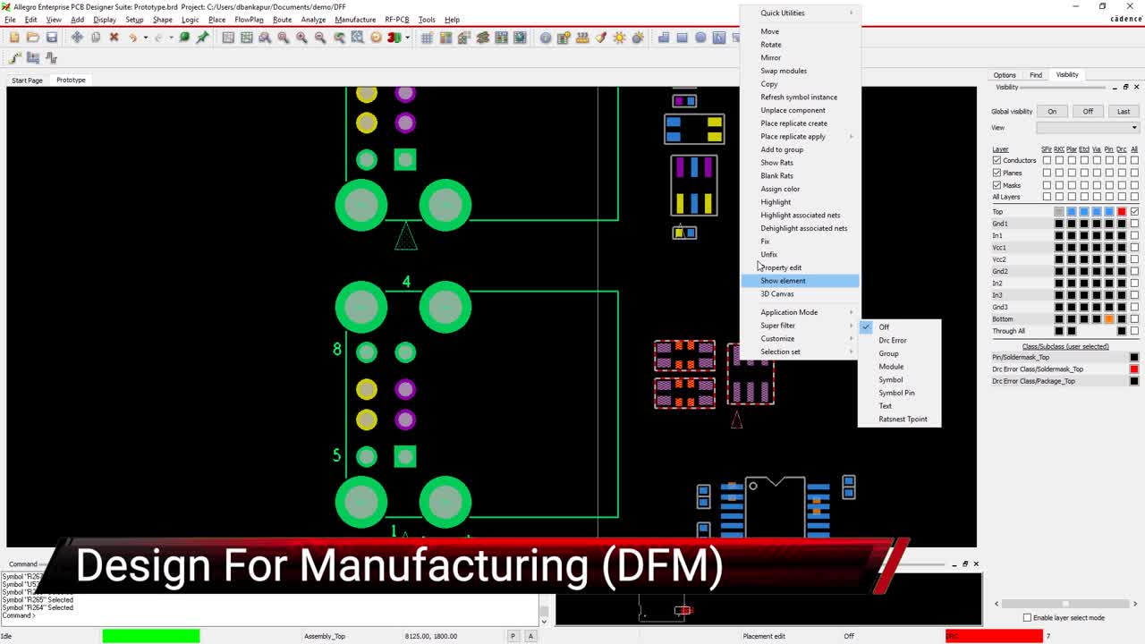
Specifying your CM’s DFA manufacturability rules
In the figure above, an example of options for defining the spacing rules between component packages for PCB assembly (PCBA) using Cadence’s OrCAD PCB Designer is shown. As illustrated, design for manufacturability rules must be included within your design software’s DRC in order to be utilized. Typically, there are three methods of incorporation, as well as three sources for the specifications, as shown below.
How to Acquire PCB Design for Manufacturing Rules
-
Built-in specifications
- Advantage:
No editing or rule creation is necessary. - Disadvantage:
Are not aligned with your CM’s equipment and processes and may not include parameters needed by your CM.
-
Industry standards
- Advantage:
Rules encompass best practices across many applications and manufacturing processes. - Disadvantage:
Do not take into account specific equipment and processes of your CM.
-
Your CM’s guidelines
- Advantage:
Ensures that your board can be built, reduces turnaround time and avoids excess costs. - Disadvantage:
Requires that you add the rules to the design package DRC, which means editing and/or creating new rules, as well as prioritizing them.
It is obvious from the options above that acquiring and using the DFM rules and guidelines from the CM that will actually be building your boards is the best choice. However, the ease of adding these rules to your DRC depends on the format that your CM provides, which can range from a listing on their website to a file transfer in an uploadable format for certain PCB design package formats. Once you have your CM’s DFM you want to utilize it most effectively, which is discussed below.
Read this free ebook to learn more about how OrCAD works with you to resolve DFM issues.
How to Best Use Your CM’s PCB Manufacturing Rules
Prior to sending your boards off to be built, you need to verify that your design specifications fall within the constraints of your CM’s design for manufacturability rules. However, this is not as simple as it sounds if you are only running the DRC at the end of design as you will most likely have to make changes many times before your board design passes the test completely. This can be improved somewhat by performing multiple checks throughout the board design stage. Yet, either of these can be extremely time-consuming as correcting one failure many times leads to the necessity for one or more other changes. The best way to save yourself from this headache is by employing real-time DRC. The ability to check and correct DFM violations in realtime can significantly shorten the verification aspect of PCBA design and get your boards to your CM faster.
This capability is a standard functionality of Cadence’s PCB Design and Analysis software package. With Allegro’s PCB DesignTrue DFM Technology you can design more accurately for your CM’s manufacturing process while ensuring your performance requirements are met.
If you’re looking to learn more about how Cadence has the solution for you, talk to us and our team of experts.