PCB Manufacturing Files: Types, Formats, and Exports
Key Takeaways
-
IPC-2581 and ODB++ serve different needs—choose based on openness, tool support, and fab preference.
-
PCB production requires multiple files, including Gerbers, with BOM, pick-and-place, STEP, and test point reports being optional but recommended.
-
OrCAD X simplifies file generation with export presets and Live DOC for drawings and documentation.
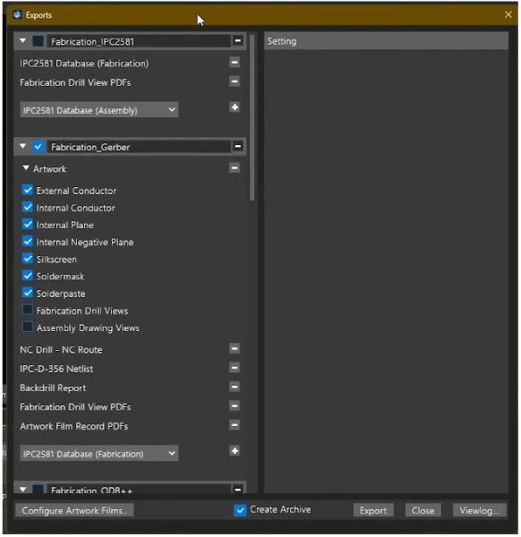
Manufacturing export window in OrCAD X
When you're ready to take your PCB design from concept to production, understanding the different types of PCB manufacturing files is key. PCB manufacturing files provide the necessary information your fabricator and assembler need to build your board accurately and efficiently. As engineers, getting these files right the first time can save considerable time, cost, and hassle.
Common PCB Manufacturing Files for Pre-Fabrication, Fabrication, Assembly, and Validation
|
Workflow Stage |
File Type |
Why It Matters (Mini Use-Case) and How to Use With OrCAD X |
|
Pre-Fabrication |
Fabrication Notes: Document material specs (copper weights, finishes), impedance targets, and special process instructions. |
|
|
Panelization Files: Lay out multiple boards on a single panel, define routing/tab cuts, fiducials and tooling holes. |
|
|
|
Fabrication |
Gerber, Drill & ODB++: Export layer artwork, solder mask, silkscreen and NC-Drill data in your fab’s preferred format. |
|
|
Impedance Reports: Generate tables of target vs. actual trace impedances based on layer stack-up. |
|
|
|
Assembly |
BOM & Pick-and-Place: Produce your parts list with reference designators and XYθ data for automated assembly. |
|
|
Stencil Aperture Files: |
|
|
|
Testing & Validation |
Test-Point Report: |
|
|
Back-Drill Instructions: Annotate which buried vias to drill out, depths, and plating requirements. |
|
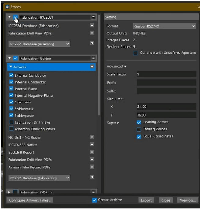
Advanced manufacturing outputs in OrCAD X include IPC-2581
Quick Discussion of PCB Manufacturing Files
Gerber and ODB++ Files
Gerber files, particularly the extended Gerber RS-274X and X2 formats, are the most common PCB fabrication files. They contain the necessary details for each layer of the PCB, including copper traces, solder mask, silkscreen, and paste layers. Gerber files must be accompanied by drill files (NC Drill or Excellon format) to specify hole sizes and locations.
-
ODB++ files are increasingly popular because they consolidate all necessary fabrication data into a single hierarchical file system. Unlike Gerber files, ODB++ files also incorporate detailed component placement, net connectivity, and stack-up data. Use ODB++ if you're working with a fab house or assembler that prefers it, or your toolchain has better support for it. It's highly capable and widely accepted, even though it has proprietary roots.
-
IPC-2581 also integrates all fabrication and assembly data into a single digital file. Use IPC-2581 if you prefer an open standard, want guaranteed interoperability, and work in a collaborative or standards-focused environment. It’s especially good for ensuring consistency in multi-vendor workflows.
ODB++ vs IPC-2581
|
Feature |
ODB++ |
IPC-2581 |
|
Origin |
Originally developed by Valor (now Siemens). Proprietary origins, but widely supported. |
Developed by IPC (industry standards body). Fully open and royalty-free. |
|
File Structure |
Hierarchical directory with multiple ASCII files. Compressed into a .tgz or .zip archive. |
Single XML-based file, optionally compressed. Follows standardized schema. |
|
Openness |
Controlled format. Free to use, but proprietary spec owned by Siemens. |
Open standard maintained by IPC consortium. Fully documented. |
|
Adoption |
Very widely used, especially in Europe and Asia. Strong toolchain support. |
Gaining ground rapidly due to open nature. Strong industry backing in North America. |
|
Data Contents |
Includes layer data, netlist, components, placement, drill, routing, stack-up, materials, etc. |
Includes same data types: layer stack, nets, components, placement, test points, etc. |
|
Customization |
More flexible for adding vendor-specific extensions. |
Structured and strict; promotes consistency across tools/vendors. |
Important Files for Manufacturing
Bill of Materials (BOM)
The Bill of Materials lists every component to be assembled on your PCB, including reference designators, component values, manufacturers, and part numbers. An accurate BOM is required for sourcing components smoothly.
Centroid (Pick-and-Place) File
This file specifies the exact position (X-Y coordinates), rotation, and side (top/bottom) for each component on your PCB. It's required for automated assembly lines, allowing quick, precise placement of components.
Other Types of PCB Manufacturing Files
Beyond the core Gerbers, drill files, BOMs and STEP models, you may also need to generate one or more of the following supplementary outputs to ensure your board is built exactly as intended:
-
Fabrication Notes: A text or PDF document that outlines board-specific requirements—material specifications, copper weights, surface finishes (e.g. ENIG, HASL), minimum annular rings, impedance tolerances and any special process instructions.
-
Panelization Files: Defines how multiple board copies are arranged on a single fabrication panel. Includes outline drawings, routing/tab locations, fiducials, tooling holes and V-score or mouse-bite paths for depanelization.
-
Impedance Control Reports: Detailed tables showing target impedances and actual layer stackup geometries (trace widths, dielectric thicknesses, dielectric constants). Crucial for high-speed or RF designs where signal integrity is paramount.
-
Back-Drill / Buried Via Instructions: Drill maps or annotated drawings that specify which vias are to be back-drilled, to what depth, and any required via plugging or plating processes to remove stubs and improve high-frequency performance.
-
Panel Fabrication Drawing: A comprehensive blueprint of the fabricated panel including material callouts, copper balance requirements, depanelization scheme, board numbering/tagging and any special markings or barcodes.
-
Readme / Release Notes: A plain-language file summarizing all included outputs, naming conventions, version history, and any last-minute changes or clarifications for the fab/assembly team.
-
Test Fixture / Probe Card Data: Pin-out listings or connector-mapping tables formatted for automated test equipment, often accompanied by CAD drawings of the fixture interface or probe card alignment features.
-
Don’t forget about other requirements your board might have—impedance control, gold fingers, or blind/buried vias. Documenting these clearly in a separate PDF or README file ensures the manufacturer understands all unique aspects of your design.
How to Generate PCB Manufacturing Files in OrCAD X
Manufacturing Tab → Export to Manufacturing
This opens a dialog box with several export options, including:
-
Gerber files
-
IPC-2581
-
NC Drill
-
BOM and others
You can choose either Gerber or IPC-2581 formats depending on your fab house’s preference. OrCAD X pre-configures most settings by default, making it beginner-friendly.
For Gerber Output
-
Select “Artwork” to manage layer-specific settings (e.g., scaling, leading/trailing zeros).
-
Click Configure Artwork Films to include any custom layers (e.g., title blocks or silkscreen details).
-
Once set, hit Export.
Optional: enable “Create Archive” to bundle all files into a single ZIP file for easy transfer to manufacturers.
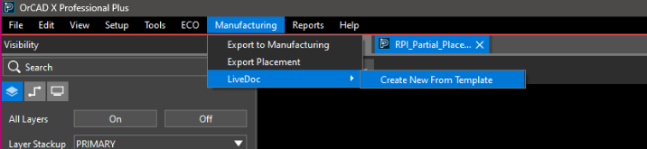
Create Assembly & Fab Drawings with Live DOC
From the Manufacturing menu, choose LiveDoc.
Live DOC is an integrated and always-up-to-date documentation editor that’s in-sync with your PCB layout and helps generate the following:
-
Stack-up tables
-
Drill summaries
-
Top/bottom copper views
-
Assembly drawings
-
Custom dimensions, notes, and graphics
You can drag and drop visual views of each layer, adjust visibility settings (e.g., turn silkscreen on/off), and add dimensions or annotations.
Export a 3D STEP File (Optional)
From the File menu, select 3D Export.
Choose:
-
Output type: STEP (widely accepted), PDF, etc.
-
Include/exclude: holes, vias, specific layers
-
Be mindful: large boards = large file sizes
These 3D files are useful for:
-
Mechanical fit checks
-
Collaborating with enclosure designers
-
Client visuals or documentation
Managing every required PCB manufacturing file can be complex without the right tools. OrCAD X streamlines this process by providing automated export options, built-in support for industry-standard file formats, and LiveDoc for creating detailed manufacturing documentation. Try OrCAD X for free or learn more about the full capabilities of the OrCAD X platform.
Leading electronics providers rely on Cadence products to optimize power, space, and energy needs for a wide variety of market applications. To learn more about our innovative solutions, subscribe to our newsletter or our YouTube channel.