C - Importing Spice Models
Appendix Overview
This appendix covers the process to be followed for importing Spice models downloaded from a web site, into PSpice A/D and making them ready to be used in a circuit. The sections covered in this appendix are:
- Introduction
- Importing text models
- Generating Part Symbols
- Configuring new model library
- Editing Model Editor created symbols
Introduction
Usually, the Spice models downloaded from a Vendor’s web site cannot be used directly in PSpice A/D. This document covers the steps to be covered before you can successfully use the downloaded models for designing your circuits.
Before you can use the simulation models downloaded from a web site in your design, you need to perform following steps:
- Importing text models
- Generating Part Symbols
- Configuring new model library
Importing text models
To import the downloaded Spice models into PSpice A/D, you need to perform the following steps.
- Rename the downloaded model to have the
.MODextension.
Renaming is required only if the downloaded model does not have a.MODextension. For example, renaming will be required if the download model has a .txt extension. - Launch the Model Editor.
- Open a new or your custom model library.
- From the Model menu, choose Import.
- In the Open dialog box, select the downloaded model with the
.MODextension and select Open.
Only the first model in the.MODfile is imported. Therefore, it is recommended that the.MODfile should not have more than one model. - From the file Menu, choose Save As. In the Save As dialog box, specify the name and location of new model library as <installation_directory>
\tools\Pspice\library\userlib.
It is preferable to create you own USERLIB library folder to store all of your custom part and model libraries for better library management. It is important that you back up your custom libraries and projects on a regular basis to avoid loss of work.
Generating Part Symbols
After you have imported the downloaded model into PSpice A/D, you need to generate part symbols for the model. You can associate a model to a symbol either by Creating New Symbols or by Using symbols from an existing symbol library or by Using Model Import wizard.
Creating New Symbols
You can create Capture symbols for the imported/downloaded models. Using Model Editor you can either create parts for all the models in a library or you can enable the auto part generation feature in Model Editor, such that part is created every time you save a model.
Creating symbol for the complete library
- Open the Model Editor.
- From the Tools menu, choose Options.
- Select Capture as the schematic editor and close the Options dialog box.
- From the File menu, choose Export to Capture Part Library.
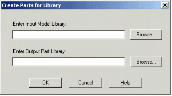
- Specify the location of the model library (
.LIB) for which you want the symbols to be created. - Specify the location of the part library (
.OLB) to be created and select OK. - A message box appears displaying status of part creation process. Select OK to close the message box.
Any errors or warning messages that are generated during the part creation, are saved in a log file named <library_name>.err. Referring to the contents of the.errfile might be helpful, in cases where part creating fails.
Creating symbol for a model
- From the Tools menu, choose Options.
- To enable part creation every time you save a model, select the Always Create Part when Saving Model check box.
- Select Capture as the schematic editor.
- Using the Save Part To group box, specify the library in which the new part should be saved and close the Options dialog box.
After making the modifications in the Options dialog box, a symbol will be generated for the part every time you save the changes in your custom model. The generated symbol will have the same name as that of the simulation model. The name and location of the part library (.OLB) will be same as that of the model library (.LIB).
.SUBCKT type, the Model Editor generates a rectangular symbol. You can edit the Model Editor generated symbol shapes. Using symbols from an existing symbol library
Instead of creating a new symbol from scratch, you can use a symbol from an existing part library, and associate it with the downloaded model. Using symbols from an existing library involves following the below steps:
Before you can use a part symbol from an existing OLB, you need to know the type of simulation model attached with the source part. If the original part symbol is attached to a device characteristic curves-based PSpice model, you only need to modify the implementation property. In case the original part symbol is attached to a template-based PSpice model, you will need to add the IMPLEMENTATION and the PSPICETEMPLATE property to the copied model.
Copying the symbol
Before you copy the part symbol, it is recommended that you create a custom Userlib folder to store your custom symbol and model libraries. Create a sub folder in the pspice folder called Userlib to store your custom libraries.
- To create a new library in Capture, from the File menu, choose New and then from the submenu, choose Library.
Copying parts within the same library
Capture does not allow direct copying and pasting of a part in the same library. Therefore, you need to complete the following steps:
- In Capture, open the symbol library from which you want to copy the symbol. From the File menu, choose Open and then choose Library.
- Click on the part to be copied so that it becomes highlighted.
- From the Edit menu choose Copy.
- Right-click on the part you just copied and select Rename.
- Type in the name of the new part and click OK.
- From the Edit menu, choose Paste to paste the original part back into the library.
Copying a part to another library
- Open two part libraries in Capture. First, the source library from which the part is to be copied and the second, the destination library to which the model is to be copied. From the File menu, choose Open | Library.
- In the Project Manager for the symbol library, position the libraries in a way to enable dragging the part from one library to another.
- While holding down the
Ctrlkey, drag and drop the required part from the source library to the destination library.
Alternatively, you can copy the desired part with 'Edit | Copy' and 'Edit | Paste' commands. - Right click on the part you just copied, select Rename, and give the part the desired part name.
Modifying the IMPLEMENTATION property
If you have used existing part symbols, you must ensure that the symbols you have copied and renamed point to the correct model. The part to model referencing is done using the Implementation property.
- To edit the value of the IMPLEMENTATION property, open the property editor by double clicking on the part. Alternatively, right-click on the part and from the popup menu choose Edit Properties.
- In the Property Editor dialog box, ensure that the Implementation Type is set to PSpice Model.
- Change the value of the Implementation property to the name specified in the model library (
.LIB) file.
In case IMPLEMENTATION property is not already present, click New Row. In the Add New Row dialog box, specify Name asImplementationand Value as the name of the simulation model in the.LIBfile.You need not specify any value in the IMPLEMENTATION PATH field, because PSpice A/D will search the model only in the libraries that are configured for the project. Model libraries will be searched in the same sequence as listed in the Library Files list box in the Libraries tab of the simulation setting dialog box.
Adding PSPICETEMPLATE property
The PSPICE TEMPLATE property is required if you want to simulate the part. This property defines the PSpice syntax required for the netlisting the part. This property is not required for parts based on PSpice A/D provided templates.
Using Model Import wizard
You can use the Model Import wizard either to generate a symbol for the imported model or to associate an existing model to the imported symbol.
Launching Model Import wizard
You can invoke Model Import wizard, using one of the methods listed below.
- Using File menu
- From the File menu in Model Editor, choose Model Import Wizard [Capture].
- Using Tools menu
- From the Tools menu, choose Options.
- Select the Always Create Part When Saving Model check box.
- Select the Pick symbols manually check box.
- Click OK.
Model Import wizard is launched whenever you save the model.
Associating Model
If you launch Model Import wizard from the File menu, in the first page of the wizard, you need to specify the path to the input simulation library as well as the location of the destination symbol library and click Next.
Model Import wizard starts the process of associate a symbol to the downloaded simulation model.
In the Associate/Replace Symbol page of the wizard, you can view the symbol associated with the downloaded model and if required, replace it with the symbol of your own choice.
- Select the Replace Symbol button.
If no symbol was associated to the model by the Model Import wizard, use the Associate Symbol button that is available instead of the Replace Symbol button. - In the Select Matching page of the wizard, specify the path to the symbol library containing the symbol to be associated with the downloaded model.
- From the Matching Symbols list, select the symbol that you want to associate with the downloaded model and click the Save Symbol button.
- In the Associate/Replace Symbol page, the selected symbol name appears against the downloaded model name. Click Finish to save your changes to the symbol library.
When you use the Model Import wizard to generate or associate symbols to a downloaded model, all the required properties, such as IMPLEMENTATION TYPE, IMPLEMENTATION, and PSPICETEMPLATE, are also updated. Therefore, you need not modify these properties manually.
Configuring new model library
After you have generated the part library for a new/customized model library, you need to make the model library available to the design. To ensure this you need to add the model library containing your custom simulation models to the project simulation profile.
- In Capture, open your Analog or Mixed-Circuit project.
- From the PSpice menu, choose Edit Simulation Profile.
- Select the Configuration Files tab.
- In the Category list box, select Library.
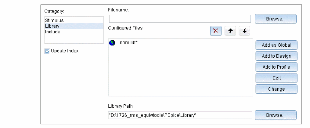
- In the Filename text box, specify the location of the model library.
- To make the library available to all designs, click Add as Global. If you want the library to be used only in the current design, select Add to Design and close the Simulation Settings dialog box.
Editing Model Editor created symbols
Depending on the model definition, different symbol shapes are generated by the Model Editor. Regular symbol shapes are generated for the standard PSpice A/D primitive models that are defined using the .MODEL statement. For devices based on a more complicated subcircuit model definition, .SUBCKT, a generic rectangle is created that interfaces with the subcircuit model.
For example, if the downloaded simulation model is an OPAMP model defined using a.SUBCKT statement, the symbol generated by the Model Editor will be a generic rectangular graphic with pins attached.
In such cases, you can edit the symbol created by the Model Editor. This section demonstrates the steps for editing the symbol generated using the Model Editor for an OPAMP simulation model LF442A.MOD, downloaded from the National Semiconductor’s web site. LF442A is a Dual Low Power JFET Input Operational Amplifier. After you download the simulation model, use the Model Editor to generate the part symbol, as explained in the Generating Part Symbols section.
- After the symbol generation is complete, open the Model Editor created symbol library in Capture.
- Launch Capture. From the Start menu choose Programs > Installed OrCAD release > Capture.
- From the File menu in Capture, choose Open > Library.
- Double click on the part for which the symbol is to be modified.
The part symbol appears as shown below.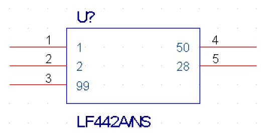 Instead of a regular triangular graphic, a rectangular graphic is generated. The numbers inside the rectangle are the pin names and the numbers outside the rectangle represent pin numbers.
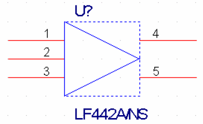
You will now edit the Model Editor generated symbol to have a triangular shape. - Delete the shape within the dotted line.
- Redraw the required figure. For an OPAMP the required figure is a triangle.
- From the Place menu, choose Line.
- Draw a triangle as shown below.
 For detailed procedure see the Editing part graphics section in Chapter 5, Creating parts for models of the PSpice A/D User Guide.
- Reposition the pins such that the inverting and the non inverting inputs are on the top left and bottom left of the modified symbol. The positive power supply should be on the top and the negative power supply at the bottom. The Output pin should be placed to the right of the modified symbol.
For repositioning pins you need to refer to the pin names as well as the model definition. This is because the pin names are used for model definition.
The relevant section from the model definition for LF442A relating pin names is shown below: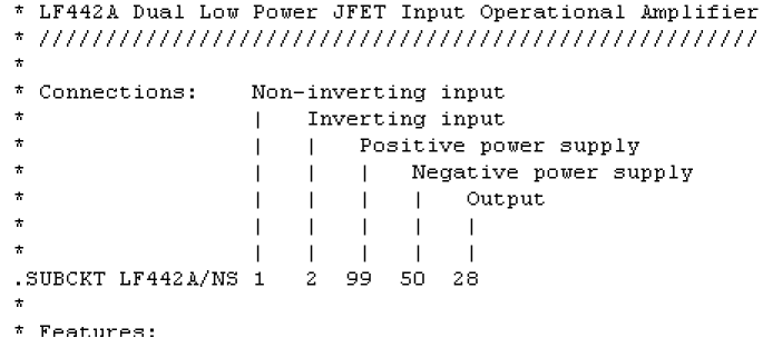 Reposition the OPAMP pins as shown in the figure below:
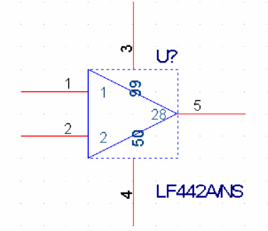 Using the line tool, draw lines to join pin numbers 3 and 4 to the modified symbol.
 - You can also change the pin numbers and the pin type using the Pin Properties dialog box.
Do not change the pin name because pin names are used in the model library (.lib) file for model definition. - After modifying the symbol as per your specifications, save the symbol and the part library.
You can now use the modified symbol in your design.
If you have any questions or comments about the OrCAD X platform, click on the link below.
Contact Us