05 - Creating Parts and PSpice Model Libraries
What’s Different About Parts Used for Simulation? Ways To Create Parts for Models Preparing Your Models for Part Creation Starting The Model Editor Using The Model Editor to Create Parts Creating Design Entry Tool Parts for All Models in a Library Example Basing New Parts on a Custom Set of Parts Editing Part Graphics (Capture Only) Attaching Models to Parts Defining Part Properties Needed for Simulation
What’s different about parts used for simulation?
A part used for simulation has these special characteristics:
- a link to a simulation model
- a netlist translation
- modeled pins
- other simulation properties specific to the part, which can include hidden pin connections or propagation delay level (for digital parts)
Ways to create parts for models
| If you want to... | Then do this... | To find out more, see this... |
|---|---|---|
|
Use the Model Editor to create parts from a model library. |
|
|
Use the Model Editor and enable automatic creation of parts. |
Using the Model Editor to create parts . If the Model Editor does not support the device type for the model definition that you want to create, then you can use a standard text editor to create a model definition using the PSpice .MODEL and .SUBCKT command syntax. |
|
Use the Export to Capture Part Library or Export to Design Entry HDL Part Library commands available in Model Editor to create parts from a model library. Use the Model Import Wizard [design entry tool to create parts from a model library.Use the Model Import Wizard [design entry tool] to create parts from a model library. |
Creating Design Entry Tool parts for all models in a library. |
Preparing your models for part creation
If you already have model definitions and want to create parts for them, you should organize the definitions into libraries containing similar device types.
To set up a model library for part creation
- If all of your models are in one file and you wish to keep them that way, rename the file to:
- Reflect the kinds of models contained in the file.
- Have the
.LIBextension.
Model libraries typically have a .LIB extension. However, you can use a different file extension as long as the file format conforms to the standard model library file format.
- If each model is in its own file, and you want to concatenate them into one file, use the DOS copy command.
Example:
You can append a set of files with.MODextensions into a single.LIBfile using the DOS command:copy *.MOD MYLIB.LIB
- Make sure the model names in your new library do not conflict with model names in any other model library.
For information on managing model libraries, including the search order PSpice A/D uses.
Starting the Model Editor
To start the Model Editor alone
- From the Windows Start menu, point to the installed Cadence release, then choose PSpice Accessories, Model Editor.
- From the File menu, choose Open or New, and enter an existing or new model library name.
- In the Models List frame, select the name of a model to display it for editing in the Spec Entry frame.
To start the Model Editor from within design entry tools
- In the schematic page editor, select the part whose model you want to edit.
- In Capture, from the Edit menu, choose PSpice Model. In Design Entry HDL, choose PSpice Simulator - Edit Model.
The Model Editor starts with the model loaded for editing.
If you have already started the Model Editor from design entry tools, and want to continue working on new models, then:
- Close the opened model library.
- Open a new model library.
- Load a device model or create a new one.
Using the Model Editor to create parts
If you want to create new parts that are not tied to a local design, open the Model Editor alone. Using Model Editor, you can create parts in two modes:
- Batch mode
- Interactive mode
Batch mode of part creation
In this method, you use the Export to Capture Part Library or Export to Design Entry HDL Part Library command from the File menu, to create part symbols for all models in a simulation library. In this approach, you can view the symbols only after all the changes have been done and saved in the .olb file. You need to open the .olb file in Capture and view the symbols.
To know more about how to use the Export to Capture Part Library or Export to Design Entry HDL Part Library command for part creation see Using batch mode.
Interactive mode of part creation
In this mode, you can view the part symbol being attached to a simulation model before the changes are saved in the symbol library. You can also update and attach symbols of your own choice to the models in the library. To create Capture or Design Entry HDL symbols in an interactive mode, choose Model Import Wizard [design entry tool] command, from the File menu.
When you generate part symbols using Model Import wizard, you can review the symbol shapes before you save the changes to the part library. This is unlike using Export To Capture Part Library or Export To Design Entry HDL Part Library command, where all the changes are made to the part library before you can review the symbols by opening them in the design entry tool.
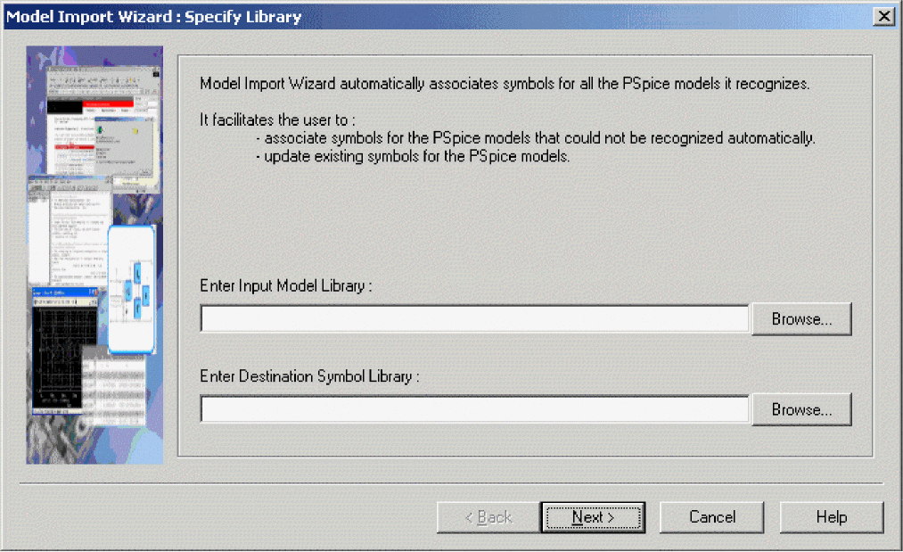
In the Model Import Wizard, specify the input model library and the output symbol library and click Next. The model names and the names of the symbol to be associated with each model is listed. The symbol shape is visible on the right.
If the users do not make any change and selects the Finish button, a message box may appear. This message box appears only if there are models for which symbols could not be found. To attach a rectangular symbols to such models click Yes. If you do not wish to attach any symbols select No. If you select yes, the symbol library generated using the Model Import Wizard will be exactly same as the .olb generated using the Export to Capture Part Library or Export to Design Entry HDL Part Library command.
To know more about how to create parts using Model Import Wizard, see Using interactive mode.
If the Model Editor does not support the device type for the model definition that you want to create, then you can use a standard text editor to create a model definition using the PSpice .MODEL and .SUBCKT command syntax. Remember to configure the new model library.
Creating Design Entry Tool parts for all models in a library
Using batch mode
- Open the Model Editor alone. From the Windows Start menu, point to the installed Cadence release, and then choose PSpice Accessories, Model Editor.
- From the File menu, choose Export to Capture Part Library or Export to Design Entry HDL Part Library, for Capture and Design Entry HDL respectively.
The Create Parts for Library dialog box appears.
Export to <design entry tool> Part Library option is available depending on the design entry tool selected as the schematic editor in the Options dialog box. To display the Options dialog box, choose Options from the Tools menu. - In the Enter Input Model Library text box, specify the location of the model library for which the design entry tool parts are to be created.
You can use the Browse button to specify a different location of theThe Enter Output Part Library text box automatically displays the name and the location of the new.OLB or .LIBfile..OLBfile (in Capture) or the folder (in Design Entry HDL where you want library files to be created. The displayed library name or folder name is same as specified by the user in the Save Part To section of the OPTIONS dialog box. - Click OK to create the part and click OK again to clear the
.ERRlog dialog box.
Recreating an already existing part library, using the Export to <design entry tool> Part Library command does not overwrite the contents of the part library. Only the new parts are appended to the library. Consider a part library,MYLIB.OLBthat has two partsa1anda2, and a model library,MYLIB.LIBthat has three modelsa2,b1, andb3. RecreatingMYLIB.OLBfromMYLIB.LIBwill not deletea1fromMYLIB.OLB. The modifiedMYLIB.OLBhas four parts,a1,a2,b1, andb2.
In Design Entry HDL:
The part library is created with the same name as the .lib file. Each model in the .lib file is represented as a separate folder, with the folder name same as the model name.
Each of the Design Entry HDL part that is created has following views.
- sym_1 - Contains graphical description of the part
- chips - Contains pin name to pin number mapping needed for packaging onto physical board.
- entity - Contains the port information for the part.
- pspice_lnk - Contains the pspice.pll file. This file points to the Advanced Analysis enabled simulation model for the part.
The pspice_lnk view is created only when you create Design Entry HDL parts for Advanced Analysis enabled PSpice models using the Model Editor.
Using interactive mode
Invoke Model Import wizard
From Model Editor
- From the File drop-down menu, choose Model Import Wizard [<design entry tool>].
To be able to generate a specific design entry tool parts using Model Editor, select the design entry tool as the schematic editor in the Options dialog box.
From Capture
- Select the Project Manager window in Capture.
- From the Tools drop-down menu, select Generate Part.
- In the Generate Part dialog box, select the Pick symbol manually check box.
- From the Netlist/source file type drop-down list box, select PSpice Model Library.
- To start the symbol generation process, click OK.
Using Model Import wizard
- In the Specify Library page of the Model Import Wizard, provide inputs.
- Specify the name and location of the input model library (
.lib) - Specify the name and location of the output part library (
.olb)
While specifying the library name, you must ensure that special characters, such as tilde (~), backtick (`), exclamation mark (!), dollar ($), percentage (%), caret (^), ampersand (&), plus (+), minus (-), comma (,), semi colon(;), single quotes ('), and double quotes (") are not used in the library name. - Click the Next button to move to the next step of the wizard.
When you click the Next button, the Model Import Wizard automatically starts the process of looking up symbols for each of the models in the.libfile and associating the symbols that match the model definition.
Model Import Wizard uses the model definition to find a matching symbol for a simulation model. Therefore, Model Import Wizard can automatically match symbols only for the device types supported by the Model Editor.
- Specify the name and location of the input model library (
- View the symbols provided by the Model Import Wizard.
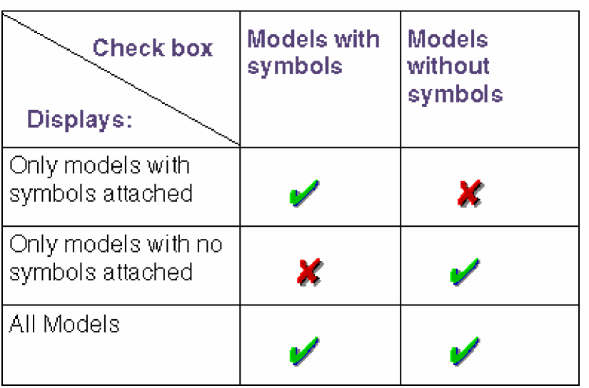
The Associate/Replace Symbol page of the wizard lists the models in the.libfile and the corresponding symbol names. By default, all models are listed. You can customize the view to display only those models that have symbols attached or the models that do not have any symbols attached.
To display only the models with symbols attached, ensure that only the Models with symbols check box is selected.
To display only the models with no symbols attached, only the Models without symbols check box should be selected. In this case, the Symbol Name column is blank
. You can view the attached symbol by selecting a model from the list of the models with attached symbols. The symbol shape appears on the right of the wizard.
At this stage, you can complete the process of associating symbols, and close the Model import wizard by clicking the Finish button. When you click the Finish button, you receive a message stating whether you want to attach rectangular symbols to the models that do not have symbols attached to them. This message appears only if the.libfile has some models for which symbols were not available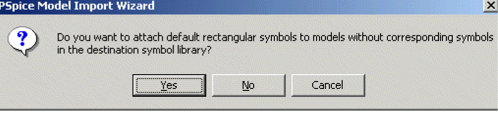 In this case, you want rectangular shaped symbols to be associated with the models, select Yes. To close the wizard without attaching rectangular symbols to the models, select No.
Yes
Destination symbol library (
.olb) has symbol looked up by the Model Import wizardNo
The
.olbfile has symbols for all the models in the.libfile. - Associate/Replace desired part symbol to a PSpice model
As the name suggests, the Associate/Replace Symbol page of the wizard can also be use to review symbol shapes and if required, attach user-defined symbols to the models.
The Model import wizard allows you to attach user-defined symbols to the models without symbols or to replace the attached symbols with a symbol of your own choice.- To change the model-symbol association suggested by Model Import wizard, click the Replace Symbol button.
- To attach a specific symbol to a model for which matching symbols could not be found, click the Associate Symbol button.
- Click the Associate/Replace symbol button.
- In the Select Matching page of the wizard, specify the path to the base library
A base library can be defined as the symbol library (.olb) that contains the desired part symbol. From the specified library, the Model Import wizard filters and lists the symbol names that can be attached to the selected model. You can then select a symbol from the list, to be associated with the model. - Complete the model terminal and symbol pin mapping.
Use the View Model Test button, to display the model definition for the selected mode. The pin names of the selected symbols appear in the Symbol Pin drop-down list box. - Select the Save button to update the destination symbol file specified in step 1, with the changes made by you.
The changes made to the destination library are irreversible. Once saved, you cannot undo the changes at the click of a button.
Similarly, you can make associate an existing symbol to any of the models in the .lib file.
When you use the Model Import wizard to attach a symbol to a model and vice-versa, following tasks are performed:
- The value of IMPLEMENTATION TYPE property attached to the symbol is set to PSpice Model.
- The value of the IMPLEMENTATION property attached to the symbol is set to the name of the selected model. (Except in case of leveled models where the level number is removed.)
- For models based on device characteristic curves, the PSPICETEMPLATE property is updated with the pinname information.
- For template-based PSpice models,
pspice_lnkview is generated.
Setting up automatic part creation
Automatic part creation from the Model Editor is optional. By default, automatic part creation is disabled. You can enable it using the procedure below.
To enable automatic part creation for new models
- In the Model Editor with a library open, choose Options from the Tools menu.
- In the Part Creation Setup frame, select Always Create Part when Saving Model if it is not already checked.
The Always Create Part when Saving Model option will be disabled if you start the Model Editor from a design entry tool. - Select the Pick symbols Manually check box, to ensure that Model Import Wizard is invoked every time you generate a part symbol for a model.
In this case, the Specify Library page of the wizard is not required and is therefore, not visible. The Associate/Replace symbol page will be invoked. - In the Save Part To frame, define the name of the part library for the new part. Choose one of the following:
- Part library path same as model library to create or open the
*.OLBfile that has the same filename as the open model library (*.LIB).
For example, if the model library is named MYPARTS.LIB, then the Model Editor creates the part library named MYPARTS.OLB. - User-defined part library, and then enter a library name in the part Library Name text box.
- Part library path same as model library to create or open the
Example
The examples covered in this section demonstrate the steps involved in creating a part using the Model Editor. The examples covered in this section are:
- Creating parts in the batch mode
- Creating parts using interactive mode
Creating parts in the batch mode
This example is the continuation of the Example: Creating template-based PSpice model used in Chapter 4, “Creating and editing models.”
The tasks covered in this example are:
- Creating parts for the models in a model library using the Export to <design entry tool> Part Library command.
- Using the Model Editor created part in a schematic design.
- Passing parameters to a simulation model from the schematic.
- Using model with multiple levels of simulation parameters. Difference in the use model for Model Editor-created model and OrCAD X supplied model
In this example, you will create parts for the simulation models in the LOCAL_LIB model library. The LOCAL_LIB library created as part of Example: Creating template-based PSpice model has a template-based model of an operational amplifier, OPA_LOCAL.
Creating design entry tool parts
To create design entry tool parts for all the models in the LOCAL_LIB.LIB library:
- From the File menu choose Export to Capture Part library for Capture parts or Export to D3esign Entry HDL Part library for Design Entry HDL parts.
The Export to Capture Part Library or Export to Design Entry Part library option is available depending on the design entry tool you select as the schematic editor in the Options dialog box. - In the Create Parts for Library dialog box, ensure that the input model library is
LOCAL_LIB.LIBand save the new design entry tool part library in the same location as the model library. - Click OK, to create parts.
In Capture:
The LOCAL_LIB.OLB that gets created has one part, OPA_LOCAL, with the LEVEL property is attached to the part symbol. By default, the value of the LEVEL property is set to 1.
Template-based operational amplifier model created using the Model Editor has multiple level support. If the value of the LEVEL property is set to 1, first level of simulation parameters are used while simulating the model. Similarly, if the LEVEL value set to 2, second level of simulation parameters are used, and so on.
in Design Entry HDL:
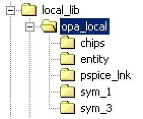
The Model Editor generated part library has 5.x architecture. The part library directory has the same name as that of the model library, local_lib. A new directory, local_lib, is generated. In the 5.x architecture, the part library further has sub directories, one for each part in the library. Therefore, the local_lib directory has a sub directory OPA_local.
With in the part library, each of the part has multiple views, such as chips, entity, pspice_lnk, and symbol views. The directory structure for the local_lib library, is shown in the figure below.
Figure 5-1 The 5.x architecture of the local_lib library
Using the Model Editor created parts in a design
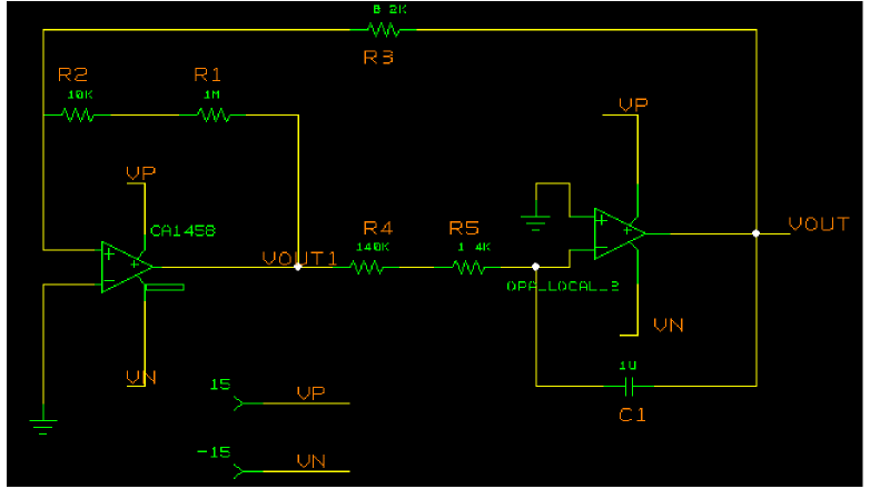
In this section you will create an amplifier using two internally compensated operational amplifiers. One of the Operational Amplifier, CA1458, is supplied along with PSpice A/D in the OPA.LIB model library, and the second Operational Amplifier used is OPA_LOCAL, created using the Model Editor. Both the models are template-based and both support multiple levels of simulation parameters.
In Capture:
- In Capture, create a new project
FUNC_GEN.OPJ, and includeLOCAL_LIB.LIBas one of the model library. - Create a circuit as shown in the figure below.
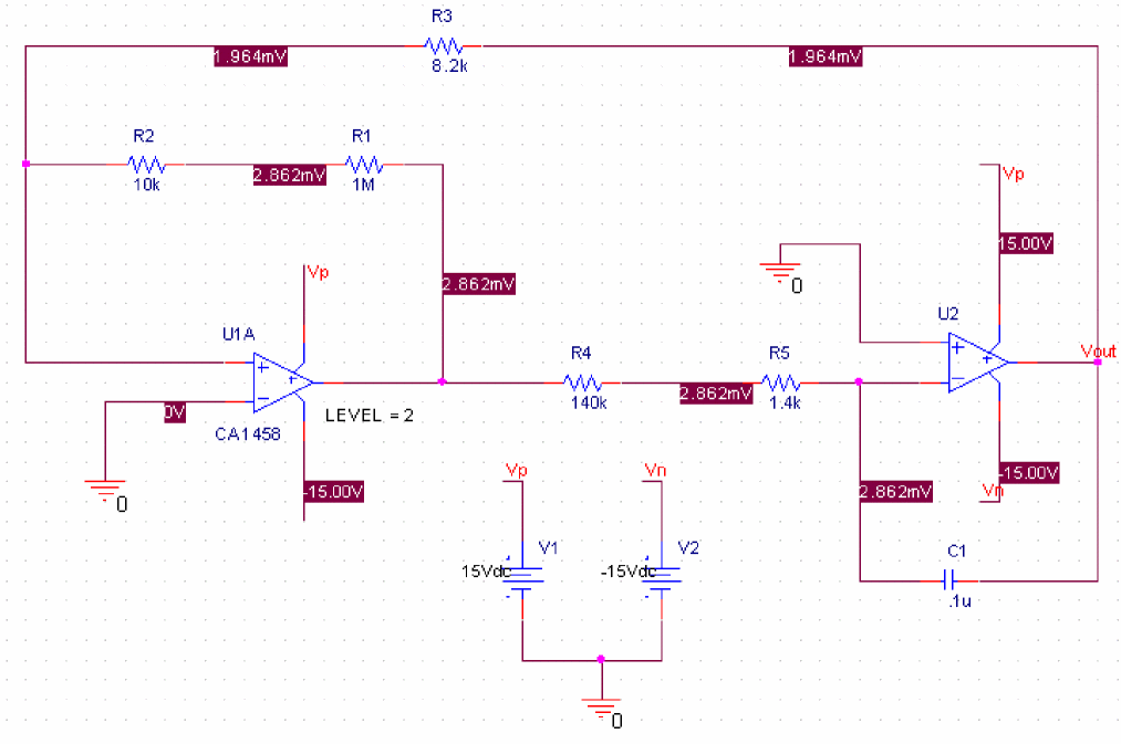 The model CA1458, is a multi-level model and by default, the model level is 3. The LEVEL property for the OPA_LOCAL model is set to 2.
- To simulate the circuit, choose Run from the PSpice menu in Capture.
In Design Entry HDL:
- In Design Entry HDL, create a new project amplifier, and include
local_lib.libas one of the model library. - Create a circuit design as shown in the figure below.
 The model CA1458, is also a multi-level model. By default, the model level is 3. For OPA_LOCAL, the value of the LEVEL property is set to 2.
..\tools\pspice\tutorial\concept\modeleditor. Besides the local_lib, and opa.lib other libraries included in the project are pspice_elem and analog. If you use the design from the hierarchy, edit the cds.lib to specify the correct location of local_lib.- To simulate the circuit, choose Run from the PSpice menu in Design Entry HDL.
Changing the level of simulation parameters used in the design
We will now modify the circuit design, such that level 2 simulation parameters are used for CA1458 and level 3 simulation parameters are used for the OPA_LOCAL model, created using the Model Editor.
Changing the level for CA1458
To change the level of simulation parameters for CA1458 from 3 to 2,
- Select the part CA1458.
- In Capture, from the Edit menu, choose Properties.
In Design Entry HDL, choose Text - Attributes. - In Capture, in the Property editor dialog box, change the value of LEVEL property from 3 to2.
In Design Entry HDL, in the Attributes dialog box, change the value of LEVEL property from 3 to 2. - In Capture, click Apply and close the Property Editor.
In Design Entry HDL, click OK to save the changes.
Similarly, change the value of the LEVEL property on OPA_LOCAL from 2 to 3.
You can now simulate the circuit using PSpice A/D or PSpice Advanced Analysis.
Changing Simulation Properties from design entry tools
For all the editable simulation properties, you can specify the value of simulation parameters from the design entry tools.
In Capture:
- Select OPA_LOCAL.
- From the Edit menu, choose Properties.
- In the Property Editor dialog box, select New Row.
- In the Add New Row dialog box, enter the name of the simulation parameter in the Name text box. Enter VOS.
- In the Value text box, add the value of the simulation parameter as 2e-3 and select OK.
- To make the property and its value visible, first select property row and then select the Display button in the Property Editor dialog box.
- Specify the Display Format. Select Name and Value.
- Select Apply and close the dialog box.
The simulation parameter and its value appear in the Capture. If you now simulate the design, the simulation parameter value specified in Capture will be used.
In Design Entry HDL:
- Select OPA_LOCAL_3.
- From the Edit menu, choose Properties.
- In the Attributes dialog box, select Add.
- In the new row enter the name of the simulation parameter in the Name text box. Enter VOS.
- In the Value text box, add the value of the simulation parameter as 2e-3 and select OK.
- To make the property and its value visible, first select property row and then select the Display button in the Property Editor dialog box.
- Specify the Display Format. Select Name and Value.
- Select Apply and close the dialog box.
The simulation parameter and its value are now visible in Design Entry HDL. If you now simulate the design, the simulation parameter value specified in Design Entry HDL will be used.
Creating parts using interactive mode
In this section, we will use the Model Import wizard to create models stored in a user defined library, MYLIB. This library consists of four simulation models. These are LM339; which is a voltage comparator macro model subcircuit, INA105E; which is an operational amplifier plus precision resistor network, LF442A/NS; which is a JFET OPAMP, and mybjt; which is a Bipolar Junction Transistor.
Launch Model Import Wizard
- From the File drop-down menu in Model Editor, choose Model Import Wizard [<design entry tool>].
Provide Inputs
- In the Specify Library page of the wizard, specify the location of
MYLIB.LIB. - Specify the name of the part library in which the part symbols generated by the Wizard are to be stored.
You can either specify the name of an existing.olbfile or create a new.olbfile.
When you specify the name of an existing.olbfile, you also need to specify if symbols should be created for all the models in the model library while replacing the existing symbols, or whether part symbols are to be created only for the models without the symbols.
The name and the location of the destination symbol library gets populated by default. For the current example, accept the default name,mylib.olband click Next.
Depending on the model definition, the Model Import wizard could locate appropriate part symbol for the BJT model only. The named of the symbol attached to themybjtmodel, is listed in the Symbol Name column and the symbol shape is also visible.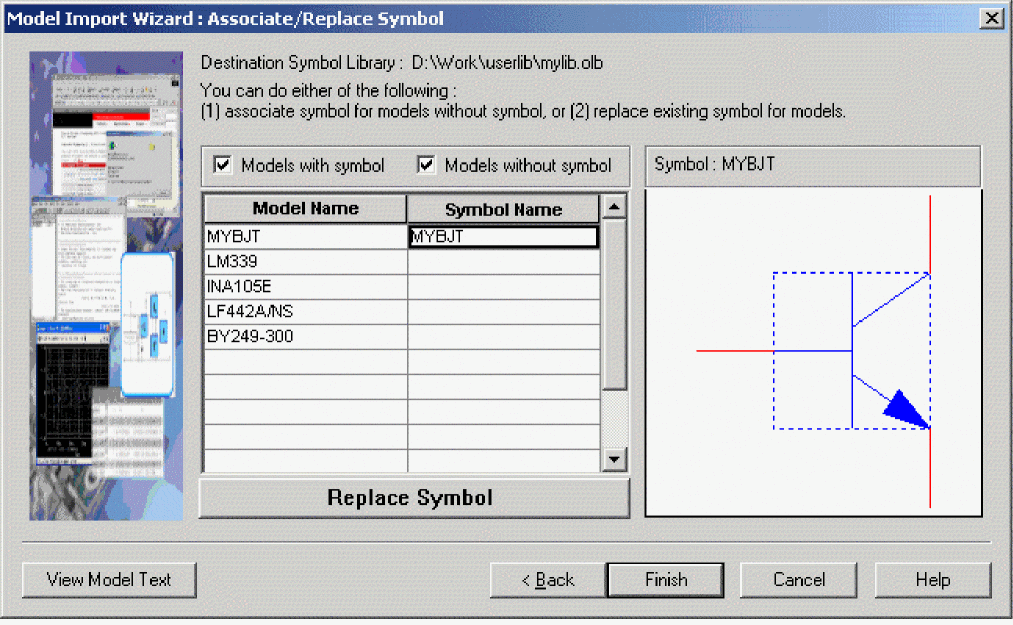
- You can now complete one of the following steps:
- Close the wizard without attaching any symbols of the rest of the three models in
mylib.lib. - Close the wizard, after Model Import wizard attaches rectangular symbols to rest of the models in
mylib.lib. - Use the Model Import wizard to select and attach an existing symbol shape to one or all the models in
mylib.lib.
- Close the wizard without attaching any symbols of the rest of the three models in
Associating desired part symbol to a PSpice model
We will now use the Model Import wizard to attach an existing user-defined, symbol to LF442A/NS; which is a JFET OPAMP. LF442A is a Dual Low Power JFET Input Operational Amplifier, downloaded from National Semiconductor's web site. We will pick up the symbol from the symbol library opamp.olb, which contains symbols for different types of OPAMPs.
- In the Associate/Replace page of the Model Import Wizard, select
LF442A/NS, and click Associate Symbol. - In the Select Matching page of the wizard, specify the name and the location of
opamp.olb.
All symbols that match the model definition are listed in the Matching Symbols list. - From the Matching symbols list, select
LM158and click Next. - Before you start mapping the model terminals to the symbol pin names, click the View Model Text button.
The model definition of LF442A/NS appears in a different window.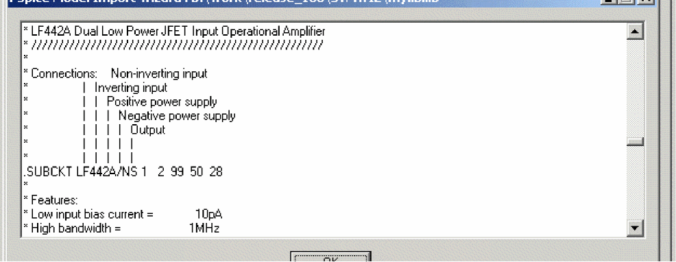
- Map the model terminals and the symbol pin names.
Model terminal Mapped to Symbol Pin 1
+
2
-
99
V+
50
V-
28
OUT
- To attach the symbol to LF442A/NS, click the Save Symbol button.
The name of the symbol attached to the model appears in the Symbol Name list.
You have successfully attached a symbol to the selected model. Similarly, you can attach models for the other two symbols as well.
Basing new parts on a custom set of parts
If you are using the Model Editor to automatically generate parts for model definitions, and you want to base the new parts on a custom graphic standard (rather than the PSpice A/D default parts), then you can change which underlying parts either application uses by setting up your own set of parts.
To create a custom set of parts for automatic part generation
- Create a part library with the custom parts.
Be sure to name these parts by their device type as shown in Table 5-1 and Table 5-2; this is how the Model Editor determines which part to use for a model definition.
For more information on creating parts, refer to the OrCAD X Capture User Guide.
Table 5-1 Symbol Names for custom symbol generation for regular PSpice models
For this device type... Use this symbol name... For this device type... Use this symbol name... Bipolar transistor: LPNP
LPNP
Magnetic core
CORE
Bipolar transistor: NPN
NPN
MOSFET: N-channel
NMOS
Bipolar transistor: PNP
PNP
MOSFET: P-channel
PMOS
Capacitor1
CAP
OPAMP: 5-pin
OPAMP5
Darlington: N-channel
DARNPN
OPAMP: 7-pin
OPAMP7
Darlington: P-channel
DARPNP
Resistor1
RES
Diode
DIODE
Switch: voltage-controlled1
VSWITCH
GaAsFET
GASFET
Transmission line1
TRN
IGBT: N-channel
NIGBT
Voltage comparator
VCOMP
Inductor1
IND
Voltage comparator: 6 pin
VCOMP6
JFET: N-channel
NJF
Voltage reference
VREF
JFET: P-channel
PJF
Voltage regulator
VREG
Table 5-2 Symbol Names for Custom Symbol Generation for template-based Models
For this device type... Use this symbol name... For this device type... Use this symbol name... Bipolar transistor: LPNP
Magnetic core
AACORE
Bipolar transistor: NPN
AANPN3
MOSFET: N-channel
AANMOSFET3
Bipolar transistor: PNP
AAPNP3
MOSFET: P-channel
AAPMOSFET3
Capacitor1
CAP
OPAMP: 5-pin
AA5_PIN_OPAMP
Darlington: N-channel
AADARNPN3
OPAMP: 7-pin
AA7_PIN_OPAMP
Darlington: P-channel
AADARPNP3
Resistor1
Diode
AADIODE
Switch: voltage-controlled1
Transmission line1
IGBT: N-channel
AANIGBT3
Voltage comparator
Inductor1
Voltage comparator: 6 pin
JFET: N-channel
AANCHANNEL3
Voltage reference
JFET: P-channel
AANPHANNEL3
Voltage regulator
AAVREG
- For each custom part, set its IMPLEMENTATION property to
`Mwhere`is a back-single quote or grave character.
This tells the Model Editor to substitute the correct model name.
To base new parts on custom parts using the Model Editor
- In the Model Editor with the library open, choose Part Creation Setup from the Options menu, and enable automatic part creation as described in To enable automatic part creation for new models .
- In the Base Parts On frame, enter the name of the existing part library (
*.OLB) that contains your custom parts. - Click OK.
Editing part graphics (Capture only)
If you created parts using the Model Editor, and you want to make further changes, the following sections explain a few important things to remember when you edit the parts.
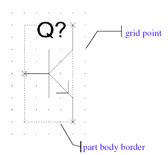
How Capture places parts
When placing parts on the schematic page, the schematic page editor uses the grid as a point of reference for different editing activities. The part’s pin ends are positioned on the grid points.
To edit a part in a library
- From Capture’s File menu, point to Open, then choose Library.
- Select the library that has the part you want to edit.
The library opens and displays all its parts. - Double-click the part you want to edit.
The part appears in the part editor. - Edit the part.
You can resize it, add or delete graphics, and add or delete pins. For more information about specific part editing tasks, refer to the OrCAD X Capture User Guide. - After you have finished editing the part, from the File menu, choose Save to save the part to its library.
Here are the things to check when editing part properties:
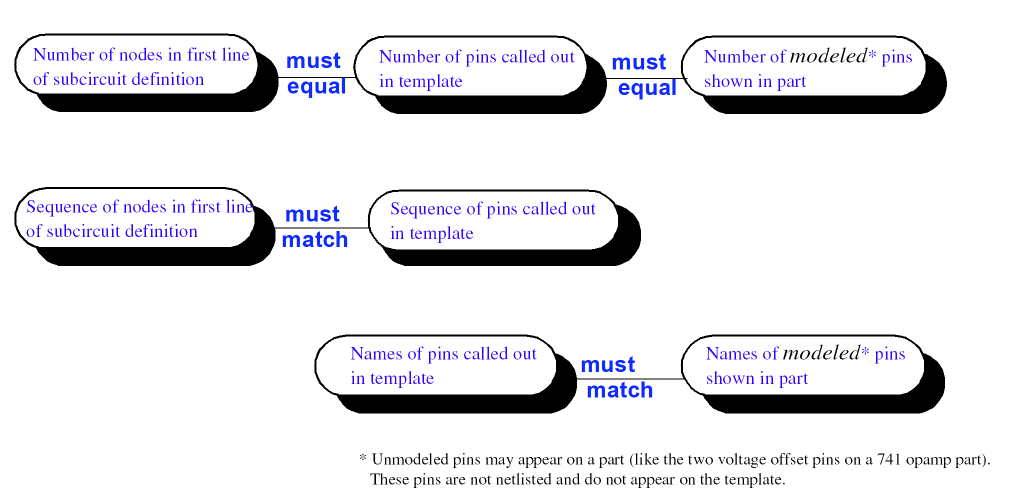
- Does the PSPICETEMPLATE specify the correct number of pins/ nodes?
- Are the pins/ nodes in the PSPICETEMPLATE specified in the proper order?
- Do the pin/ node names in the PSPICETEMPLATE match the pin names on the part?
Defining grid spacing
Grid spacing for graphics
The grid, denoted by evenly spaced grid points, regulates the sizing and positioning of graphic objects and the positioning of pins. The default grid spacing with snap-to-grid enabled is 0.10", and the grid spacing is 0.01".
You can turn off the grid spacing when you need to draw graphics in a tighter space.
To edit the part graphics
- In Capture’s part editor, display the part you want to edit.
- Select the line, arc, circle, or other graphic object you want to change, and do any of the following:
- To stretch or shrink the graphic object, click and drag one of the size handles.
- To move the entire part graphic, click and drag the edge of the part.
The part body border automatically changes to fit the size of the part graphic.
- After you have finished editing the part, from the File menu, choose Save to save the part to its library.
Grid spacing for pins
The part editor always places pins on the grid, even when the snap-to-grid option is turned off. The size of the part is relative to the pin-to-pin spacing for that part. That means that pins placed one grid space apart in the part editor are displayed as one grid space apart in the schematic page editor.
Pins must be placed on the grid at integer multiples of the grid spacing. Because the default grid spacing for the Schematic Page Grid is set at 0.10", you will achieve the best results by setting pin spacing in the Part and Symbol Grid at 0.10" intervals from the origin of the part and at least 0.10" from any adjacent pins. For more information about grid spacing and pin placement, refer to the OrCAD X Capture User Guide.
The part editor considers pins that are not placed at integer multiples of the grid spacing from the origin as off-grid, and a warning appears when you try to save the part.
Here are two guidelines:
- Make sure Pointer Snap to Grid is enabled when editing part pins and editing schematic pages so you can easily make connections.
- Make sure the Part and Symbol Grid spacing matches the Schematic Page Grid spacing.
- change pin names
or - delete pins
In these cases you must adjust the value of the part’s PSPICETEMPLATE property to reflect these changes. To find out how, see Pin callout in subcircuit templates.
Attaching Models to Parts
If you create parts and want to simulate them, you need to attach model implementations to them. If you created your parts using any of the methods discussed in this chapter, then your part will have a model implementation already attached to it.
MODEL
The IMPLEMENTATION property defines the name of the model that PSpice A/D must use for simulation. When attaching this implementation, this rule applies:
- The Implementation name should match the name of the .MODEL or .SUBCKT definition of the simulation model as it appears in the model library (
*.LIB).
Example:
If your design includes a 2N2222 bipolar transistor with a .MODEL name of Q2N2222, then the Implementation name for that part should be Q2N2222.
To attach a model implementation
- In the schematic page editor, double-click a part to display the Parts spreadsheet of the Property Editor.
Assume the spreadsheet is displayed in columns and follow the instructions below. - Click on the empty cell under the Implementation Type column.
A drop-down list appears in the cell. - From the Implementation Type drop-down list, select PSpice Model.
- Click on the empty cell under the Implementation column, and type the name of the model to attach to the part.
You do not need to enter an Implementation Path because PSpice A/D searches for the model in the list of model libraries you configure for this project. - Click Apply to update the design, then close the Parts spreadsheet.
In case you want to reuse the part symbol that was originally attached to a characteristic curve-based model, with a template-based simulation model, you must delete the PSPICETEMPLATE property from the part symbol.
Example:
Consider a scenario where you have two simulation models for a bipolar transistor, with the same name 2n2222 in two different libraries. First simulation model is based on characteristic curves and the second based on PSpice templates. Both the simulation models have same name, therefore the same value for the IMPLEMENTATION property.
The simulation model based on characteristic curves, which is of .MODEL type, is used in a schematic design. The part symbol for the bipolar transistor will have the IMPLEMENTAION property set to Q2n2222 and the PSPICETEMPLATE property attached to it. Now modify the BJT symbol by attaching a template-based model to the symbol. The value of the IMPLEMENTATION property will not change because the name of the template-based model is same as that of the characteristic curves-based model. Therefore, to ensure that the correct model is used during simulation, you must delete the PSPICETEMPLATE property from the part symbol and configure the library containing the template-based BJT model.
You can check whether the right model is being used or not, by viewing the simulation netlist generated by PSpice A/D. The simulation netlist for a .MODEL type BJT model starts with Q, where as the simulation netlist for a .SUBCKT model starts with X.
Defining part properties needed for simulation
If you created your parts using any of the methods discussed in this chapter, then your part will have these properties already defined for it:
- PSPICETEMPLATE for simulation in both Capture and Design Entry HDL
- PART and REFDES for identification in Capture
- LOCATION for identification in Design Entry HDL
You can also add other simulation-specific properties for digital parts: IO_LEVEL, MNTYMXDLY, and PSPICEDEFAULTNET (for pins).
Example:
If you create a part that has electrical behavior described by the subcircuit definition that starts with:
.SUBCKT 7400 A B Y
+ optional: DPWR=$G_DPWR DGND=$G_DGND
+  params: MNTYMXDLY=0 IO_LEVEL=0
then the appropriate part properties are:
IMPLEMENTATION = 7400
MNTYMXDLY = 0
IO_LEVEL = 0
PSPICETEMPLATE = X^@REFDES %A %B %Y %PWR %GND
 @MODEL PARAMS:IO_LEVEL=@IO_LEVEL MNTYMXDLY=@MNTYMXDLY
To edit a property needed for simulation in Capture:
- In the schematic page editor, select the part to edit.
- From the Edit menu, choose Properties to display the Parts spreadsheet of the Property Editor.
- Click in the cell of the column you want to change (for example, PSPICETEMPLATE), or click the New button to add a property (and type the property name in the Name text box).
- If needed, type a value in the Value text box.
- Click Apply to update the design, then close the spreadsheet.
To edit a property needed for simulation in Design Entry HDL:
- From the Text menu in Design Entry HDL, choose Attributes.
- Click on the part to display the Attributes dialog box.
- Click in the Name text box of the property you want to change (for example, PSPICETEMPLATE), or click the Add button to add a property (and type the property name in the Name text box).
- Specify the value of the property in the Value text box.
- Click OK to save the changes and close the Attributes dialog box.
Here are the things to check when editing part properties:
- Does the PSPICETEMPLATE specify the correct number of pins/ nodes?
- Are the pins/ nodes in the PSPICETEMPLATE specified in the proper order?
- Do the pin/ node names in the PSPICETEMPLATE match the pin names on the part?
Table 5-3
To find out more about this property... See this... PSPICETEMPLATE
IO_LEVEL
MNTYMXDLY
PSPICEDEFAULTNET
PSPICETEMPLATE
The PSPICETEMPLATE property defines the PSpice syntax for the part’s netlist entry. When creating a netlist, the design entry tool substitutes actual values from the circuit into the appropriate places in the PSPICETEMPLATE syntax, then saves the translated statement to the netlist file.
Any part that you want to simulate must have a defined PSPICETEMPLATE property. These rules apply:
- The pin names specified in the PSPICETEMPLATE property must match the pin names on the part.
- The number and order of the pins listed in the PSPICETEMPLATE property must match those for the associated .MODEL or .SUBCKT definition referenced for simulation.
- The first character in a PSPICETEMPLATE must be a PSpice device letter appropriate for the part (such as Q for a bipolar transistor).
Device types and PSpice device letters are also listed in the PSpice A/D Reference Guide.
Creating parts not intended for simulation Some part libraries contain parts designed only for board layout; PSpice A/D cannot simulate these parts. This means they do not have PSPICETEMPLATE properties or that the PSPICETEMPLATE property value is blank.
PSPICETEMPLATE syntax
The PSPICETEMPLATE contains:
- regular characters that the schematic page editor interprets verbatim
- property names and control characters that the schematic page editor translates
Regular characters in templates
Regular characters include the following:
- alphanumerics
- any keyboard part except the special syntactical parts used with properties (@ & ? ~ #).
- white space
An identifier is a collection of regular characters of the form:
alphabetic character [any other regular character]*.
Property names in templates
Property names are preceded by a special character as follows:
[ @ | ? | ~ | # | & ]<identifier>
The schematic page editor processes the property according to the special character as shown in the following table.
| This syntax... | Is replaced with this... |
|---|---|
|
@<id> |
Value of <id>. Error if no <id> attribute or if no value assigned. |
|
&<id> |
Value of <id> if <id> is defined. |
|
?<id>s...s |
Text between s...s separators if <id> is defined. |
|
?<id>s...ss...s |
Text between the first s...s separators if <id> is defined, else the second s...s clause. |
|
~<id>s...s |
Text between s...s separators if <id> is undefined. |
|
~<id> s...ss...s |
Text between the first s...s separators if <id> is undefined, else the second s...s clause. |
|
#<id>s...s |
Text between s...s separators if <id> is defined, but delete rest of template if <id> is undefined. |
Separator characters include commas (,), periods (.), semicolons (;), forward slashes (/), and vertical
bars ( | ). You must always use the same character to specify an opening-closing pair of separators.
Example: The template fragment ?G|G=@G||G=1000| uses the vertical bar as the separator between the if-then-else parts of this conditional clause. If G has a value, then this fragment translates to G=<G property value>. Otherwise, this fragment translates to G=1000.
The ^ character in templates
The schematic page editor replaces the ^ character with the complete hierarchical path to the device being netlisted.
The \n character sequence in templates
The part editor replaces the character sequence \n with a new line. Using \n, you can specify a multi-line netlist entry from a one-line template.
The % character and pin names in templates
Pin names are denoted as follows:
%<pin name>
where pin name is one or more regular characters.
The schematic page editor replaces the %<pin name> clause in the template with the name of the net connected to that pin.
The end of the pin name is marked with a separator (see Property names in templates). To avoid name conflicts in PSpice A/D, the schematic page editor translates the following characters contained in pin names.
| This pin name character... | Is replaced with this... |
|---|---|
|
< |
l (L) |
|
> |
g |
|
= |
e |
|
\XXX\ |
XXXbar |
%% in the template.Example: R^@REFDES ... for a resistor
PSPICETEMPLATE examples
Simple resistor (R) template
The R part has:
- two pins: 1 and 2
- two required properties: REFDES and VALUE
Template
R^@REFDES %1 %2 @VALUE
Sample translation
R_R23 abc def 1k
where REFDES equals R23, VALUE equals 1k, and R is connected to nets abc and def.
Voltage source with optional AC and DC specifications (VAC) template
The VAC part has:
- two properties: AC and DC
- two pins: + and -
Template
V^@REFDES %+ %- ?DC|DC=@DC| ?AC|AC=@AC|
Sample translation
V_V6 vp vm DC=5v
where REFDES equals V6, VSRC is connected to nodes vp and vm, DC is set to 5v, and AC is undefined.
Sample translation
V_V6 vp vm DC=5v AC=1v
where, in addition to the settings for the previous translation, AC is set to 1v.
Parameterized subcircuit call (X) template
Suppose you have a subcircuit Z that has:
- two pins: a and b
- a subcircuit parameter: G, where G defaults to 1000 when no value is supplied
To allow the parameter to be changed on the schematic page, treat G as an property in the template.
Template
X^@REFDES %a %b Z PARAMS: ?G|G=@G|
 ~G|G=1000|
Equivalent template (using the if...else form)
X^@REFDES %a %b Z PARAMS: ?G|G=@G||G=1000|
Sample translation
X_U33 101 102 Z PARAMS: G=1024
where REFDES equals U33, G is set to 1024, and the subcircuit connects to nets 101 and 102.
Sample translation
X_U33 101 102 Z PARAMS: G=1000
where the settings of the previous translation apply except that G is undefined.
Digital stimulus parts with variable width pins template
For a digital stimulus device template (such as that for a DIGSTIM part), a pin name can be preceded by a * character. This signifies that the pin can be connected to a bus and the width of the pin is set to be equal to the width of the bus.
Template
U^@REFDES STIM(%#PIN, 0) %*PIN
 \n+ STIMULUS=@STIMULUS
where #PIN refers to a variable width pin.
Sample translation
U_U1 STIM(4,0) 5PIN1 %PIN2 %PIN3 %PIN4
+ STIMULUS=mystim
where the stimulus is connected to a four-input bus, a[0-3].
Pin callout in subcircuit templates
The number and sequence of pins named in a template for a subcircuit must agree with the definition of the subcircuit itself—that is, the node names listed in the .SUBCKT statement, which heads the definition of a subcircuit. These are the pinouts of the subcircuit. To find out how to define subcircuits, refer to the .SUBCKT command in the PSpice A/D Reference Guide.
Example:
Consider the following first line of a (hypothetical) subcircuit definition:
.SUBCKT SAMPLE 10 3 27 2
The four numbers following the name SAMPLE—10, 3, 27, and 2—are the node names for this subcircuit’s pinouts.
Now suppose that the part definition shows four pins:
IN+ OUT+ IN- OUT-
The number of pins on the part equals the number of nodes in the subcircuit definition.
If the correspondence between pin names and nodes is as follows:
| This node name... | Corresponds to this pin name... |
|
10 |
IN+ |
|
3 |
IN- |
|
27 |
OUT+ |
|
2 |
OUT- |
then the template looks like this:
X^@REFDES %IN+ %IN- %OUT+ %OUT- @MODEL
The rules of agreement (rules for pin callout in subcircuit templates) are outlined in the following figure.
IO_LEVEL
All digital parts provided in the PSpice libraries have an IO_LEVEL property.
The IO_LEVEL property defines what level of interface subcircuit model PSpice A/D must use for a digital part that is connected to an analog part.
To use the IO_LEVEL property with a digital part
- Add the IO_LEVEL property to the part and assign a value shown in the table below.
Table 5-7
Assign this value... To use this interface subcircuit (level)... 0
circuit-wide default
1
AtoD1 and DtoA1
2
AtoD2 and DtoA2
3
AtoD3 and DtoA3
4
AtoD4 and DtoA4
- Use this property in the PSPICETEMPLATE property definition (IO_LEVEL is also a subcircuit parameter used in calls for digital subcircuits).
Example:PSPICETEMPLATE=X^@REFDES %A %B %C %D %PWR %GND @MODEL PARAMS:\n+ IO_LEVEL=@IO_LEVEL MNTYMXDLY=@MNTYMXDLY
MNTYMXDLY
All digital parts provided in the PSpice libraries have a MNTYMXDLY property.
The MNTYMXDLY property defines the digital propagation delay level that PSpice A/D must use for a digital part.
To use the MNTYMXDLY property with a digital part
- Add the MNTYMXDLY property to the part and assign a value shown in the table below.
Assign this value... To use this propagation delay... 0
circuit-wide default
1
minimum
2
typical
3
maximum
4
worst-case (min/max)
- Use this property in the PSPICETEMPLATE property definition (MNTYMXDLY is also a subcircuit parameter used in calls for digital subcircuits).
Example:PSPICETEMPLATE=X^@REFDES %A %B %C %D %PWR %GND @MODEL PARAMS:\n+ IO_LEVEL=@IO_LEVEL MNTYMXDLY=@MNTYMXDLY
PSPICEDEFAULTNET
The PSPICEDEFAULTNET pin property defines the net name to which a hidden (invisible) pin is connected. Hidden pins are typically used for power and ground on digital parts.
To use the PSPICEDEFAULTNET property with a digital part
- For each PSPICEDEFAULTNET property, assign the name of the digital net to which the pin is connected.
Example:
If power (PWR) and ground (GND) pins of a digital part connect to the digital nets $G_DPWR and $G_DGND, respectively, then the PSPICEDEFAULTNET properties for these pins are:PSPICEDEFAULTNET=$G_DPWR
PSPICEDEFAULTNET=$G_DGND
- Use the appropriate hidden pin name in the PSPICETEMPLATE property definition.
Example:
If the name of the hidden power pin is PWR and the name of the hidden ground pin is GND, then the template might look like this:PSPICETEMPLATE=X^@REFDES %A %B %C %D %PWR %GND @MODEL PARAMS:\n+ IO_LEVEL=@IO_LEVEL MNTYMXDLY=@MNTYMXDLY
View the next document: 06 - Analog Behavioral Modeling
If you have any questions or comments about the OrCAD X platform, click on the link below.
Contact Us